1
SYSTEM DESIGN
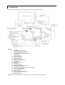
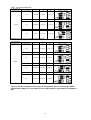
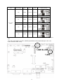
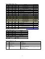
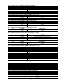
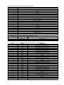
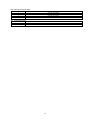
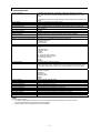
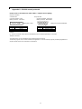
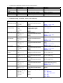
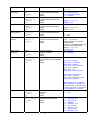
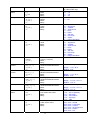
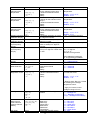
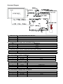
A typical LCD based display system utilising this controller is likely to comprise the following:
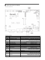
Summary:
1.
2.
3.
4.
5.
6.
7.
8.
9.
10.
11.
12.
13.
14.
15.
16.
17.
18.
19.
20.
21.
22.
23.
24.
25.
26.
LCD panel
LCD controller card, SVH-1920
LCD signal cable (use for LVDS panel)
LCD signal cable (use for TTL panel)
Inverter for backlight (if not built into LCD)
Inverter cable
Function controls
Function controls cable
Status LED (optional)
IR sensor (optional)
RS-232 control interface
Audio add-on board (optional)
Analog RGB input
DVI-I input
Composite video input
S-Video input
Component video input
Alternate composite and S-Video input
HD-Component video input
Interface for connection with to HD-SDI adaptor board
+12V / +24V DC power input
External panel power input
Auxiliary video input
Auxiliary +5VDC, max 500mA output
Ambient light sensor connection
Backlight status input
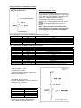
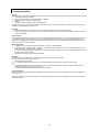
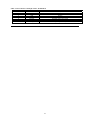
Digital View provides a range of parts, such as listed above, to make up complete display solutions.
3