1
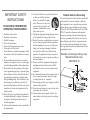
McIntosh Laboratory, Inc. 2 Chambers Street Binghamton, New York MXA60 60th Anniversary Integrated Audio System Owner’s Manual 13903-2699 Phone: 607-723-3512 www.mcintoshlabs.com The lightning flash with arrowhead, within an equilateral triangle, is intended to alert the user to the presence of uninsulated “dangerous voltage” within the product’s enclosure that may be of sufficient magnitude to constitute a risk of electric shock to persons. WARNING - TO REDUCE RISK OF FIRE OR ELECTRICAL SHOCK, DO NOT EXPOSE THIS EQUIPMENT TO RAIN OR MOISTURE. CAUTION - Invisible Laser Radiation when open. DO NOT stare into the beam or view directly with optical instruments. Use of controls or adjustments or performance of procedures other than those specified in the Owners Manual may result in Hazardous Radiation Exposure. LUOKAN 1 LASERLAITE KLASS 1 LASER APPARAT VAROITUS! VARNING! Laitteen kayttaminen muulla kuin tassa kayttoohjeessa mainitulla tavalla saattaa altistaa kayttajan turvallisuusluokan 1 ylittavalle nakymattomalle lasersateiiylle. Om apparaten anvands pa annat satt an i denna bruksanvisning specificerats, kan anvandaren utsattas for osynbg laserstraining, som overskrider gransen for laserklass 1. This product incorporates an embedded CLASS 3R Laser (IEC60825-1). 2 The exclamation point within an equilateral triangle is intended to alert the user to the presence of important operating and maintenance (servicing) instructions in the literature accompanying the appliance. NO USER-SERVICEABLE PARTS INSIDE. REFER SERVICING TO QUALIFIED PERSONNEL. To prevent the risk of electric shock, do not remove cover or back. No user-serviceable parts inside. The Caution Label below is located inside the apparatus on the top of the laser transport IMPORTANT SAFETY INSTRUCTIONS! PLEASE READ THEM BEFORE OPERATING THIS EQUIPMENT. 1. Read these instructions. 2. Keep these instructions. 3. Heed all warnings. 4. Follow all instructions. 5. Do not use this apparatus near water. 6. Clean only with a dry cloth. 7. Do not block any ventilation openings. Install in accordance with the manufacturer’s instructions. 8. Do not install near any heat sources such as radiators, heat registers, stoves, or other apparatus (including amplifiers) that produce heat. 9. Do not defeat the safety purpose of the polarized or grounding-type plug. A polarized plug has two blades with one wider than the other. A grounding type plug has two blades and a third grounding prong. The wide blade or the third prong are provided for your safety. If the provided plug does not fit into your outlet, consult an electrician for replacement of the obsolete outlet. 10. Protect the power cord from being walked on or pinched particularly at plugs, convenience receptacles, and the point where they exit from the apparatus. 11. Only use attachments/accessories specified by the manufacturer. 12. Use only with the cart, stand, tripod, bracket, or table specified by the manufacturer, or sold with the apparatus. When a cart is used, use caution when moving the cart/ apparatus combination to avoid injury from tip-over. 13. Unplug this apparatus during lightning storms or when unused for long periods of time. 14. Refer all servicing to qualified service personnel. Servicing is required when the apparatus has been damaged in any way, such as powersupply cord or plug is damaged, liquid has been spilled or objects have fallen into the apparatus, the apparatus has been exposed to rain or moisture, does not operate normally, or has been dropped. 15. Do not expose this equipment to dripping or splashing and ensure that no objects filled with liquids, such as vases, are placed on the equipment. 16. To completely disconnect this equipment from the a.c. mains, disconnect the power supply cord plug from the a.c. receptacle. 17. The mains plug of the power supply cord shall remain readily operable. 18. Do not expose batteries to excessive heat such as sunshine, fire or the like. 19. Connect mains power supply cord only to a mains socket outlet with a protective earthing connection. Outdoor Antenna Grounding If an outside antenna or cable system is connected to the product, be sure the antenna or cable system is grounded so as to provide some protection against voltage surges and built-up static charge. Article 810 of the National Electrical Code, ANSI/ NFPA 70, provides information with reguards to proper grounding of the mast and supporting structure, grounding of the lead-in wire to an antenna discharge unit, and size of ground conductors, location of antenna-discharge unit, connection to ground electrodes and requirements for the grounding electrode. Example of antenna grounding as per National Electrical Code, ANSI/NFPA 70 3 Thank You Your decision to own this McIntosh MXA60 Integrated Audio System ranks you at the very top among discriminating music listeners. You now have “The Best.” The McIntosh dedication to “Quality,” is assurance that you will receive many years of musical enjoyment from this unit. Please take a short time to read the information in this manual. We want you to be as familiar as possible with all the features and functions of your new McIntosh. Please Take A Moment The serial number, purchase date and McIntosh Dealer name are important to you for possible insurance claim or future service. The spaces below have been provided for you to record that information: Serial Number:________________________________ Purchase Date:_ _______________________________ Dealer Name:_ ________________________________ Technical Assistance If at any time you have questions about your McIntosh product, contact your McIntosh Dealer who is familiar with your McIntosh equipment and any other brands that may be part of your system. If you or your Dealer wish additional help concerning a suspected problem, you can receive technical assistance for all McIntosh products at: McIntosh Laboratory, Inc. 2 Chambers Street Binghamton, New York 13903 Phone: 607-723-3512 Fax: 607-724-0549 4 Customer Service If it is determined that your McIntosh product is in need of repair, you can return it to your Dealer. You can also return it to the McIntosh Laboratory Service Department. For assistance on factory repair return procedure, contact the McIntosh Service Department at: McIntosh Laboratory, Inc. 2 Chambers Street Binghamton, New York 13903 Phone: 607-723-3515 Fax: 607-723-1917 Table of Contents Safety Instructions....................................................... 2 Thank You and Please Take a Moment........................ 4 Technical Assistance and Customer Service............... 4 Table of Contents......................................................... 4 General Information.................................................... 5 Disc Information.......................................................... 5 Connector and Cable Information............................... 5 Introduction.................................................................. 6 Performance Features............................................... 6-7 Dimensions...............................................................8-9 Rear Panel Connections............................................. 10 Connections Connecting Antennas.................................................11 Connecting Components....................................... 12-13 Connecting the MXA60 with a Subwoofer.......... 14-15 Connecting the MXA60 to an external Power Amplifier and Loudspeakers............................................16-17 Remote Control Remote Control Push-buttons.................................... 18 How to use the Remote Control................................. 19 Front Panel Functions Front Panel Displays, Controls, Push-buttons and Jack................................................ 20 Front Panel Disc Information Display....................... 21 Setup Mode How to Operate the Setup Mode............................... 22 Default Settings......................................................... 22 Firmware Version....................................................... 23 How to set the Source Name...................................... 23 How to set the Source Level...................................... 23 How to set the Speakers............................................. 24 The Tuner Type.......................................................... 24 Tuner Clear Presets.................................................... 24 Tuner Regions............................................................ 25 Tuner Text Information.............................................. 25 Operation How to Operate the Audio Amplifier................... 26-29 How to Operate the Tuner..................................... 29-32 How to Operate the SACD/CD Player.................. 33-35 Additional Information Photo.......................................................................... 36 Specifications........................................................ 37-38 Packing Instructions.................................................. 39 Copyright 2009 © by McIntosh Laboratory, Inc. General Information, Disc Information, Connector and Cable Information General Information 1. For additional connection information, refer to the owner’s manual(s) for any component(s) connected to the MXA60 Integrated Audio System. 2. The Main AC Power going to the MXA60 and any other McIntosh Component(s) should not be applied until all the system components are connected together. Failure to do so could result in malfunctioning of some or all of the system’s normal operations. When the MXA60 and other McIntosh Components are in their Standby Power Off Mode, the Microprocessor’s Circuitry inside each component is active and communication is occurring between them. 3. In the event the MXA60 Power Amplifier overheats, due to improper ventilation and/or high ambient temperature, the protection circuits will activate. The Front Panel Power Guard LEDs will continuously indicate ON and the audio will be muted. When the MXA60 has returned to a safe operating temperature, normal operation will resume. 4. The MXA60’s built-in speaker protection incorporates an automatic resetting solid-state device in the crossover network. The protection allows a certain amount of overdrive, but extended periods will trigger protection. If there is an obvious reduction of sound level the Protection Device may have activated. The device will automatically reset when the volume level setting on the MXA60 is reduced significantly and kept low until the output of the affected Loudspeaker returns to normal. 5. When discarding the unit, comply with local rules or regulations. Batteries should never be thrown away or incinerated but disposed of in accordance with the local regulations concerning battery disposal. 5. For additional information on the MXA60 and other McIntosh Products please visit the McIntosh Web Site at www.mcintoshlabs.com. Disc Information 1. Compact Discs that are not round (e.g. Novelty discs with octagonal or heart shapes) will not play properly in the MXA60 and should not be tried, as possible damage may occur. 2. The MXA60 SACD/CD Player is designed to play all standard CD Audio Discs that conform to the Official Compact Disc Standards which is indicated by the Symbol. It will also play most CD-R and CD-RW discs, however some recorded discs may not be able to play due to the condition of the recording. 3. CD Audio Discs recorded in the MP3 and WMA Formats will play on the MXA60, except discs that contain multi-session recordings. Some MP3 or WMA recorded discs may not be able to play due to the condition of the recording. When ever possible, set the writing software to the ISO9660 Level 1 standard. 4. The CD audio side of the Dual Disc does not meet the Compact Disc Digital Audio specifications found in the industry “Redbook”; the MXA60 may not read Dual Discs. 5. Several of the SACD performance features available on the MXA60 are active only if the SACD Disc includes the supporting encoded information. Connector and Cable Information XLR Connectors Below is the Pin configuration for the XLR Balanced Input Connectors on the MXA60. Refer to the diagram for connection: PIN 1: Shield/Ground PIN 2: + Output PIN 3: - Output PIN 2 PIN 1 PIN 3 Power Control Connector The MXA60 Power Control Output Jack sends Power On/Off Signal (12V) when conPower nected to other McIntosh ComControl ponents. A 1/8 inch stereo mini N/C phone plug is used for connection Ground to the Power Control Output on the MXA60. Note: The Power Control Connecting Cable is available from the McIntosh Parts Department: Power Control Cable Part No. 170-202 Six foot, shielded 2 conductor, with 1/8 inch stereo mini phone plugs on each end. RAA2 Connectors Pin No. 1. 2. 3. 4. 5. 6. 7. 8. Wire Color White/Orange Orange Pin 8 White/Green Blue White/Blue Pin 1 Green White/Brown Brown *Cable outer shield Pin 1 *Cable outer shield Pin 8 Note: The RAA2 Connecting Cable is available from the McIntosh Parts Department: RAA2 Antenna Cable Part No. 171844 Twenty foot, shielded 8 conductor, with a shielded RJ45 connector on each end. 5 Introduction Performance Features Now you can take advantage of traditional McIntosh standards of excellence in the MXA60 Integrated Audio System. The Power Amplifier section of the MXA60, with a power output of 75 watts per channel, will drive the McIntosh Loudspeakers to a high level of performance. The flexible Preamplifier section provides connections for external input sources and may also be used to drive an external Power Amplifier. The MXA60 AM/FM/STEREO Tuner Circuitry uses the latest in technology for the best sound quality with superb station reception. Audio SACD and CDs are reproduced with flawless realism and the advanced mechanical design of the transport ensures many years of smooth trouble free operation. McIntosh Acoustic Engineers have achieved in the design of the MXA60 Loudspeaker System a level of high performance. The MXA60 provides superior spaciousness sound reproduction with unusual sound stage depth in a full range system. The MXA60 reproduction is sonically transparent and absolutely accurate. The McIntosh Sound is “The Sound of the Music Itself.” • Power Output The MXA60 consists of a 75 watts per channel stereo Power Amplifier with less than 0.05% distortion. The Power Amplifier uses Thermal Trak1 Output Transistors for lower distortion and cool operation. The amplifier bias is precisely controlled over a wide range of music conditions • Power Guard The patented McIntosh Power Guard circuit prevents amplifier clipping and protects the McIntosh Loudspeakers. • Illuminated Power Meters The large Illuminated Power Output Watt Meters on the MXA60 respond to 95% of a full scale reading to a single cycle tone burst at 2,000 Hz signal. When the pointer reaches its peak it pauses long enough for the human eye to perceive its position, then decays. • Electronic Switching The Preamplifier uses Electronic and Electromagnetic Switches for reliable, noiseless switching. • Vacuum Tube Preamplifier The preamplifier section includes vacuum tube amplification. The vacuum tube is illuminated amber during the warmup period and green during operation. • Balanced and Unbalanced Inputs The Balanced Input allows the connection of a source component using long cable lengths without a loss in 1 6 ThermalTrak™ and ON Semiconductor are trademarks of Semiconductor Components Industries, LLC sound quality. The Unbalanced input has high sensitivity for compatibility with battery powered personal players. • External Input Level Match and Renaming The MXA60 External Inputs may be renamed and the volume levels are adjustable to match the volume level of the built-in Tuner and SACD/CD Player. • Precision Tracking Volume Control Volume levels are controlled by a Digitally Controlled Attenuator System with a tracking accuracy of 0.1dB. • Variable Rate Volume and Balance Control Selection The Preamplifier’s Volume and Balance Control Circuitry provides an ideal rate of change with control rotation. • Electronic Tone Controls with Auto Bass Electronic Bass and Treble Circuitry allows volume level adjustments for low and high frequencies in precise one Decibel Steps. The Auto Bass circuit automatically increases the volume of low frequencies when listening at low volume levels. • Information Service The MXA60 will indicate various text information such as Station Call Sign, Music Genre, Artist Name and Song Title when transmitted by the Radio Station. • Special FM RF Tuned Circuitry The MXA60 RF Circuitry receives strong local FM Station Signals without distortion and receives even the weakest of FM Signals with low noise. Introduction and Performance Features • RAA2 External AM Antenna The RAA2 External AM Antenna allows placement of the AM Antenna for the best reception. • Power Control The Power Control Output connection provides convenient Turn-On/Off of McIntosh Source Components. • Preset Stations and Permanent Memory The MXA60 Tuner stores up to nine AM and FM Station Presets and they are retained in Permanent Memory. • Remote Control The Custom Designed Remote Control provides control of MXA60 Functions. The Remote Control is McIntosh built in a rugged brushed aluminum extrusion case. Twin IR Emitters offer long operating range. • Twin Laser Pickup The MXA60 incorporates two laser elements, with different wavelengths, that are focused through one lens assembly. This unique design allows reading both the CD and Super Audio Compact Disc (SACD) Formats. • Advanced Transport The MXA60 transport has a Die Cast Mechanism Base and Disc Tray. It has the latest in advanced digital servo for faster, quieter and accurate operation. The Disc Audio Data is read at twice the normal rate ensuring better disc tracking and error correction processing. • Super Audio Disc Playback The MXA60 plays the higher resolution SACD Discs with extreme precision and musical elegance. • Multi-Bit Digital to Analog Converter The 24-bit, 192kHz Digital to Analog Converter has a wide dynamic range and extremely low distortion. • Multifunction Fluorescent Display The Front Panel Display indicates source selection, volume level, tone adjustments, setup functions, tuner functions and the current disc playback status. • Precision Parts Only the finest precision 1% tolerance resistors are used throughout. • Titanium Dome Tweeter The three-quarter inch titanium dome tweeter with magnetic-fluid cooled voice coil (for less thermal compression) has the ability to produce frequencies up to 45,000 Hz. • Integrated Loudspeaker Design In creating the MXA60 Loudspeaker System, all of the components making up the loudspeaker including the Woofer/Midrange, Tweeter, Crossover Network and the Enclosure with Grille, were designed to achieve correct time arrival in the reproduced musical sound (also known as group delay). • Special Power Supply Fully regulated Power Supplies and a special R-Core Power Transformer ensure stable noise free operation even though the power line varies. • Cast Aluminum Enclosure with port High quality, rigid, durable cast aluminum enclosure is finished in a high gloss, piano black. The optimized rear-ported enclosure design reduces distortion at low frequencies. • Fiber Optic Solid State Front Panel Illumination The even Illumination of the Front Panel is accomplished by the combination of custom designed Fiber Optic Light Diffusers and extra long life Light Emitting Diodes (LEDs). • Versatile Loudspeaker Placement An integrated foot gives the option of positioning the speaker up-right or at the same angle as the MXA60 electronics. • Glass Front Panel and Super Mirror Chassis Finish The famous McIntosh Illuminated Glass Front Panel and the Stainless Steel Chassis with Super Mirror Finish ensures the pristine beauty of the MXA60 will be retained for many years. • High Excursion Driver A high excursion 4” Woofer/Midrange with very large magnetic flux stabilizing elements delivers louder sound and lower bass notes with less distortion. • Gold Plated Connectors The MXA60 Power Amplifier and Loudspeaker Terminal Connectors are gold plated for superior corrosion resistance and high electrical conductivity. • Headphone Jack The MXA60 has a front panel one-quarter inch headphone jack and amplifier for private listening. 7 Dimensions The following dimensions can assist in determining the best location for your MXA60. Front Views of the MXA60 22" 5" 55.88cm 12.7cm 11-1/2" 29.21cm 10-5/8" 10-7/8" 26.99cm 27.62cm Rear Views of the MXA60 10-7/8" 27.62cm 10-3/4" 27.31cm 8 9-15/16" 24.24cm 10-5/8" 26.99cm Dimensions Top View of the MXA60 Loudspeaker Side Views of the MXA60 10-3/4" 27.7cm 10-11/16" 10-5/8" 27.15cm 26.99cm Front View of the MXA60 Loudspeaker without the grille 2-1/2" 6.35cm 10-1/2" 8-3/4" 22.23cm 26.67cm 5-5/16" 13.49cm 14-7/8" 37.79cm 9 Rear Panel Connections Balanced INPUT 2 accepts high level program source signals MAIN/SUB sends signals to a separate external Power Amplifier or a powered Subwoofer RIGHT OUTPUT connections for an 8 ohm loudspeaker LEFT OUTPUT connections for an 8 ohm loudspeaker RAA2 AM ANT (Antenna) connects to the supplied McIntosh RAA2 Remote Antenna 75 OHM FM ANT (Antenna) connects to the supplied FM Dipole Antenna, external FM Antenna or FM Cable 10 Connect the MXA60 power cord to a live AC outlet. Refer to information on the back panel of your MXA60 to determine the correct voltage for your unit Main Fuse holder, refer to information on the back panel of your MXA60 to determine the correct fuse size and rating Unbalanced INPUT 1 accepts high level program source signals POWER CONTROL Outputs send a turn-on signal to a McIntosh Component when the MXA60 is On Connecting Antennas Connecting Antennas Antenna Connections: 1. Using the supplied AM Antenna Shielded Cable, connect one end into the RAA2 AM Antenna jack and the other end of the same cable into the MXA60 Tuner jack labeled RAA2 AM ANT. FM Dipole Antenna Note: If a longer AM Antenna Cable is needed, refer to page 4 “Connector and Cable Information”. 2. Connect the supplied “T” shaped FM Dipole Antenna to the MXA60 75 OHM FM ANT Connector. Note: Optionally, connect a 75 ohm coax cable from a FM Antenna or cable system. 3. Proceed to “Connecting Components”. Mounting the FM Dipole Antenna Tune to a station with the weakest signal and orient the top of the “T” shaped Dipole Antenna for maximum signal with minimum noise and distortion. After the location is determined, the FM Dipole Antenna may be secured to a suitable surface by using push pins, refer to the illustration to the right. Mounting the RAA2 AM Antenna Tune to a station with the weakest signal and orient the RAA2 Antenna for maximum signal with minimum noise and distortion. After the location is determined, the RAA2 AM Antenna may be secured to a suitable surface by using two #6 1-3/4 to 2 inches (4.44 to 5.08cm) long screws, refer to the illustration to the right. 11 Connecting Components Caution: The supplied AC Power Cord should not be connected to the Rear Panel of the MXA60 Integrated Audio System until after all Connections have been made. The MXA60 has the ability to automatically switch power On/Off to McIntosh Source Components via the Power Control connections. The connection instructions below together with the Connection Diagram on the next page is an example of a typical MXA60 Audio System. Your system may vary from this, however the actual components would be connected in a similar manner. For additional information refer to “Connector and Cable Information” on page 5. Power Control Connections: 1. Optionally, connect a Control Cable from a MXA60 PWR CTRL (Power Control) Jack to the Power Control In jack on a Music Sever. 2. Connect any additional Source Components in a similar manner, as outlined in step 1. Audio Connections: 3. Optionally, connect an Audio Cable from the MXA60 INPUT 1 Input Jacks to the Music Server Output Jacks. 4. Connect any additional Source Components in a similar manner, as outlined in step 3. Loudspeaker Connections: 5. Use the supplied Loudspeaker Connecting Cables with color coded ends (red and black) to connect the MXA60 Electronic Chassis Left and Right Output Terminals to the Left and Right Input Terminals on the Loudspeakers, being careful to observe the correct polarities. Note: If the MXA60 Loudspeakers need to be located at a distance greater than the supplied Loudspeakers Connection Cables allow, proceed to “Optional Loudspeaker Connections”. 12 Optional Loudspeaker Connections: When connecting Loudspeakers to the MXA60, it is very important to use cables of adequate size so there is negligible power loss in the cables. The size is specified in Gauge Numbers or AWG (American Wire Gauge). The smaller the Gauge number, the larger the wire size: Loudspeaker Cable Distance vs Wire Gauge Guide Loudspeaker Impedance 25 feet (7.62 meters) or less 50 feet (15.24 meters) or less 100 feet (30.48 meters) or less 8 Ohms 16AWG 14AWG 12AWG 6. Prepare the Loudspeaker Hookup Cables that attach to the Amplifier by choosing one of the methods below: Bare wire cable ends: Carefully remove sufficient insulation from the cable ends, refer to figures 1, 2 & 3. If the cable Figure 2 Figure 3 Figure 1 is stranded, carefully twist the strands together as tightly as possible. Note: If desired, the twisted ends can be tinned with solder to keep the strands together, or attach spade lug or banana connector. Spade lug or prepared wire connection: Insert the spade lug connector or prepared section of the cable end into the terminal side access hole, and tighten the terminal cap until the cable is firmly clamped into the terminal so the wires cannot slip out. Refer to figures 4, 5 & 6. Banana plug connection: Insert the banana plug into the hole at the top of the terminal. Refer to figure 7. Note: Banana Plugs are for use in the United States and Canada only. 7. Connect the cables from the MXA60 Electronic Chassis Left and Right Output Terminals to the Left and Right Input Terminals on the Loudspeakers, being careful to observe the correct polarities. AC Power Cords Connections: 8. Connect the MXA60 and any remaining components’ AC Power Cords to a live AC outlet as illustrated. Connecting Components Right Loudspeaker Red (+) Left Loudspeaker Red (+) Red (+) Black (-) Red (+) Black (-) Loudspeaker Cable Loudspeaker Cable Black (-) Black (-) Optional Music Server Connect to AC Outlet 13 Connecting the MXA60 with a Subwoofer Caution: The supplied AC Power Cord should not be connected to the Rear Panel of the MXA60 Integrated Audio System until after all Connections have been made. The MXA60 has the ability to automatically switch power On/Off to McIntosh Source Components and Powered Subwoofer via the Power Control connections. The connection instructions below together with the Connection Diagram on the next page is an example of a typical MXA60 Audio System with Powered Subwoofer. Your system may vary from this, however the actual components would be connected in a similar manner. For additional information refer to “Connector and Cable Information” on page 5. Power Control Connections: 1. Connect a Control Cable from a MXA60 PWR CTRL (Power Control) Jack to the Power Control In jack on the Powered Subwoofer. 2. Optionally, connect a Control Cable from a MXA60 PWR CTRL (Power Control) Jack to the Power Control In jack on a Music Sever. 3. Connect any additional Source Components in a similar manner, as outlined in step 1. Audio Connections: 4. Connect an Audio Cable from the MXA60 MAIN/SUB R Output Jack to the Powered Subwoofer R Input Jack. 5. Optionally, connect an Audio Cable from the MXA60 INPUT 1 Input Jacks to the Music Server Output Jacks. 6. Connect any additional Source Components in a similar manner, as outlined in step 3. Loudspeaker Connections: 7. Use the supplied Loudspeaker Connecting Cables with color coded ends (red and black) to connect the MXA60 Electronic Chassis Left and Right 14 Output Terminals to the Left and Right Input Terminals on the Loudspeakers, being careful to observe the correct polarities. Note: If the MXA60 Loudspeakers need to be located at a distance greater than the supplied Loudspeakers Connection Cables allow, proceed to “Optional Loudspeaker Connections”. Optional Loudspeaker Connections: When connecting Loudspeakers to the MXA60, it is very important to use cables of adequate size so there is negligible power loss in the cables. The size is specified in Gauge Numbers or AWG (American Wire Gauge). The smaller the Gauge number, the larger the wire size: Loudspeaker Cable Distance vs Wire Gauge Guide Loudspeaker Impedance 25 feet (7.62 meters) or less 50 feet (15.24 meters) or less 100 feet (30.48 meters) or less 8 Ohms 16AWG 14AWG 12AWG 8. Prepare the Loudspeaker Hookup Cables that attach to the Amplifier by choosing one of the methods below: Bare wire cable ends: Carefully remove sufficient insulation from the cable ends, refer to figures 1, 2 & 3. If the cable is stranded, carefully twist the strands together as Figure 2 Figure 3 tightly as pos- Figure 1 sible. Note: If desired, the twisted ends can be tinned with solder to keep the strands together, or attach spade lug or banana connector. Spade lug or prepared wire connection: Insert the spade lug connector or prepared section of the cable end into the terminal side access hole, and tighten the terminal cap until the cable is firmly clamped into the terminal so the wires cannot slip out. Refer to figures 4, 5 & 6. Banana plug connection: Insert the banana plug into the hole at the top of the terminal. Refer to figure 7. Note: Banana Plugs are for use in the United States and Canada only. 9. Connect the cables from the MXA60 Electronic Chassis Left and Right Output Terminals to the Left and Right Input Terminals on the Loudspeakers, being careful to observe the correct polarities. AC Power Cords Connections: 10. Connect the MXA60 and any remaining components’ AC Power Cords to a live AC outlet as illustrated. Subwoofer Activation: 11. To activate the use of of a Powered Subwoofer with the MXA60, the “Speaker” setting in the Setup Mode needs to be changed. Please refer to the Setup Mode starting on page 22 and “Speaker” settings on page 24. Connecting the MXA60 with a Subwoofer Right Loudspeaker Red (+) Red (+) Left Loudspeaker Red (+) Black (-) Red (+) Black (-) Loudspeaker Cable Loudspeaker Cable Black (-) Black (-) Connect to AC Outlet Optional Subwoofer Optional Music Server 15 Connecting the MXA60 to an external Power Amplifier and Loudspeakers Caution: The supplied AC Power Cord should not be connected to the Rear Panel of the MXA60 Integrated Audio System until after all Connections have been made. The MXA60 has the ability to automatically switch power On/Off to McIntosh Source Components and External Power Amplifier via the Power Control connections. The connection instructions below together with the Connection Diagram on the next page is an example of a typical MXA60 Audio System with an External Power Amplifier and large Loudspeakers. Your system may vary from this, however the actual components would be connected in a similar manner. For additional information refer to “Connector and Cable Information” on page 5. Power Control Connections: 1. Connect a Control Cable from a MXA60 PWR CTRL (Power Control) Jack to the Power Control In jack on the Power Amplifier. 2. Optionally, connect a Control Cable from a MXA60 PWR CTRL (Power Control) Jack to the Power Control In jack on a Music Server. 3. Connect any additional Source Components in a similar manner, as outlined in step 1. Audio Connections: 4. Connect Audio Cables from the MXA60 MAIN/ SUB L and R Output Jacks to the External Power Amplifier L and R Input Jacks. 5. Optionally, connect an Audio Cable from the MXA60 INPUT 1 Input Jacks to the Music Server Output Jacks. 6. Connect any additional Source Components in a similar manner, as outlined in step 3. 16 Loudspeaker Connections: 7. Refer to the Loudspeakers Owners Manual for connection to the External Power Amplifier. AC Power Cords Connections: 8. Connect the MXA60 and any remaining components’ AC Power Cords to a live AC outlet as illustrated. External Power Amplifier Activation: 9. To activate the use of an External Power Amplifier with the MXA60, the “Speaker” setting in the Setup Mode needs to be changed. Please refer to the Setup Mode starting on page 22 and “Speaker” settings on page 24. Connecting the MXA60 to an external Power Amplifier and Loudspeakers Optional Music Server Right Loudspeaker Left Loudspeaker Connect to AC Outlet Power Amplifier (partial view) 17 Remote Control Push-Buttons LED illuminates during the time a remote command is sent to the MXA60 Powers the MXA60 ON or OFF Adjusts the volume level up Adjusts the volume level down Mutes the audio Accesses the Text Display Mode when playing SACD Discs containing information. Also displays various text information on FM Stations (station dependent) Selects various disc information, including time, on the Display. It is also used to cancel the text display mode on a SACD Disc Activates random playback of tracks from SACD and CD Discs Selects SACD or CD Tracks from a hybrid disc for playback. Press to Seek up the dial to find the next AM/FM Station 18 Selects the next source and adjusts various Trim functions Selects the previous source and adjusts various Trim functions Selects various Trim functions Activates the PLAY ► or PAUSE Disc functions. Tunes Up p the dial to the next FM or AM Station. STOPs ■ playback of a Disc. Tunes Down q the dial to the next FM or AM Station Selects the NEXT : track on the Disc. PSET p goes upwards through the Station Presets Selects the PREVIOUS 9 track on the Disc. PSET ▼ goes downwards through the Station Presets How to use the Remote Control How to use the Remote Control The Remote Control is capable of performing most Operating Functions for the MXA60 Integrated Audio System. Pause Press the Pause ► /TUNp Push-button to temporarily stop playback of the disc. Input Source Selection Press INP/TRIM ▲ or ▼ Push-button to select the next or Back and Next Press the : /PSET p Push-button to move forward one track or the 9 /PSET ▼ Push-button to move back to the beginning of the current track playing. Press and hold either Push-button to rapidly skip tracks. Note: If the 9 /PSET Push-button is pressed during Note: Refer to the “How to Operate” Section of this manual for additional information using this Remote Control. previous program source. Volume Press the VOL p or q Push-buttons to raise or lower the listening volume level. Mute Press the MUTE Push-button to mute the audio. The word MUTE will appear on the Front Panel Information Display. To un-mute the audio, press the MUTE Push-button again. Manual Tuning Press the ► /TUNp Push-button or the ■ /TUN ▼ to move from station to station (AM or FM). Automatic Tuning Press the LAYER/SEEK to move to the next station (AM or FM) up the dial. Preset Tuning Press the 9 PSET ▼ or : PSET p Push-button and the MXA60 will stop on the Station Preset in Memory. Note: For information on entering a Station into memory, refer to pages 30 and 31. Trim Press the TRIM Push-button until the desired Trim function (Bass, Balance, Treble, Tuner Functions, etc.) appears on the Front Panel Information display, then press the INP/TRIM p or q Push-button to adjust the Trim setting. Note: Press and release the TRIM Push-button at any time to recall the last Trim Function Selected. For additional information on the Trim Functions refer to pages 26, 27 and 28. playback of the first three seconds of the track, the MXA60 will start playing back the previous track from the beginning. If the Display is indicating time, it will momentarily indicate the track number. SACD or CD Track Selection Press the LAYER/SEEK Push-button once to display the layer selected on a SACD/CD Hybrid Disc. Press the Push-button twice to change from current layer to the other layer for playback. Time Press the TIME Push-button to access various disc times. It is also used to return the Display to indicate time instead of text information on a SACD Disc. Text Press the TEXT Push-button to select the various text information on a SACD Disc such as Album, Artist and Track Titles (disc dependent). Also displays various information such as Station Call Leters, Artist Name, Song Title and Music Genre on FM Stations (station depen- dent). 19 Front Panel Displays, Controls, Push-buttons and Jack Meter indicates the Left Channel Output of the amplifier LED indicates when the Left Channel Amplifier POWER GUARD circuit activates INFORMATION DISPLAY indicates the Sources, Volume, other Audio Settings, Operational Functions and Setup Mode Settings LED indicates when the Right Channel Amplifier POWER GUARD circuit activates TUNE /p TRIM q Control (outer knob) allows tuning of radio stations, adjustment of various types of Trim Audio Settings. It is also used in the setup mode for various functions IR Sensor receives commands from a Remote Control VOLUME Control allows adjustment of the listening level for both channels; pushing in the Volume Control will switch the MXA60 ON or OFF. It is also used in the setup mode for various functions. Pushing in and holding the Volume Control will reset the microprocessors INPUT/TRIM Control (inner knob) allows the selection of various sources for listening. Selects various Trim Audio Settings for adjustment. It is also used in the setup mode for various functions Indicates when the MXA60 is in standby mode STORE/CLEAR Pushbutton used to store into memory and clear from memory radio station presets Connection for low impedance dynamic headphones, for private listening Disc Tray opens to load and unload a disc Allows moving backward one track at a time Allows moving forward one track at a time 20 Meter indicates the Right Channel Output of the amplifier Stops disc playback. Opens and Closes the disc tray for loading or unloading discs Selects various playback times for indication on the display Disc Information Display Selects the SACD or CD Audio Tracks from a hybrid disc Starts disc playback. Use to Pause during playback Front Panel Disc Information Display Indicates when in the Pause Mode Indicates the type of disc loaded, CD or SACD Indicates the Random Play Mode is active Indicates when the Play Mode is active Indicates when the tracks on the CD disc are MP3 or WMA encoded Indicates the number of tracks on the Disc, the current Track Time, Remaining Track Time, Total Disc Playing Time, Text and various other Information 21 How to Operate the Setup Modes Your McIntosh MXA60 has been factory configured for operating settings allowing immediate enjoyment of superb audio without the need for further adjustments. If you wish to make changes to the factory default settings, a Setup Feature is provided to customize the operating settings using the Front Panel Information Display. Refer to figure 5 while performing the following steps. Note: If the MXA60 is currently On, proceed to step 2. 1. Press the VOLUME CONTROL in to switch On the MXA60. The title “SOURCE: TUNER FM TUBE WARMUP” will appear on the Front Panel Information Display. The MXA60 will go through a brief startup intialization with the Front Panel Information Display indicating the last used source and volume setting. This is followed by the volume setting indication starting at zero and then increasing to the last used volume setting. Refer to figures 1, 2 and 3. 2. Press and hold in the INPUT/TRIM Control (inner knob) until the Front Panel Upper Display indicates SETUP: VERSION MXA60 V1.00 or higher. Refer to figure 4. Note: The Front Panel Upper Display will indicate MXA60 V1.00 or higher for the first time. After the first time it will display the Setup Mode Menu item last accessed. 3. To exit from the Setup Mode, press the INPUT/ TRIM Control (inner knob). The Front Panel upper Display will revert back to its normal display. Refer to figure 3. Default Settings Default Settings Function Name Setting Page No. V_._ _ 23 SOURCE NAME INPUT 1 INPUT 2 23 SOURCE LEVEL1 INPUT 1 INPUT 2 23 SPEAKERS MXA60 24 TM3_ _ _ _ _ _ _ 24 TUNER CLEAR PRESETS NONE 24 TUNER REGION ______ 25 ON 25 VERSION 1 TUNER TYPE TUNER TEXT In order to change the Source Name and Level for Input 1 and Input 2, either Input needs be selected before entering the Setup Mode. 1 The Default Settings Chart below indicates the Function Name, Default Setting and the Page Number for additional information. SOURCE: CD TUBE WARMUP Figure 1 SOURCE: TUNER FM 30% Figure 2 91.5 MHz WWWW-FM ST ¦ Figure 3 SETUP: VERSION MXA60 V1.00 Figure 4 22 Figure 5 Setup Firmware Version The MXA60 functionality is controlled by internal software that is know as Firmware. The Version of the Firmware in the MXA60 can be identified at any time by utilizing the Setup Mode. 1. Press and hold in the INPUT/TRIM Control (inner knob) until the Setup Mode is active. 2. The Front Panel Information Display will indicate “SETUP: VERSION MXA60 V_ . _ _”. Refer to figure 4. 3. The number after the character “V” is the Firmware number. 4. Proceed to “Source Name1” or exit from the Setup Mode, by pressing the INPUT/TRIM Control (inner knob). The Front Panel Information Display will revert back to its normal display. Source Name1 character “S” appears instead of the “I”. Refer to figure 7. SETUP: SOURCE NAME INPUT1: -> SNPUT1 Figure 7 6. Rotate the TUNE/▲TRIM▼ Control (outer knob) to select the “N” of the title “Input 1”. 7. Slowly rotate the VOLUME Control until the character “E” appears instead of the “N”. 8. Repeat the method used in steps 6 and 7 until the word “Input 1” is replaced with the word “Server”. Refer to figure 8. SETUP: SOURCE NAME INPUT1: -> SERVER Figure 8 The MXA60 allows for renaming (up to eight characters long) of the two External Inputs to match the components in your system. In the following example Input 1 will be renamed Server. Follow the steps below for renaming Input 1: 1. Rotate the INPUT/TRIM Control (inner knob) to select Input 1. 2. Press and hold in the INPUT/TRIM Control (inner knob) until the Setup Mode is active. 3. Rotate the INPUT/TRIM Control (inner knob) to select “SETUP: SOURCE NAME”. Refer to figure 6. SETUP: SOURCE NAME INPUT1: -> INPUT1 Figure 6 4. Rotate the TUNE/▲TRIM▼ Control (outer knob) to select the “I” of the title “Input 1”, the charcter “I” should be flashing On and Off. 5. Slowly rotate the VOLUME Control until the 9. Proceed to “Source Level ” or exit from the Setup Mode, by pressing the INPUT/TRIM Control (inner knob). The Front Panel Information Display will revert back to its normal display. 1 Source Level1 The source components connected to the External Inputs can have slightly different volume levels than the AM, FM, CD Inputs of the MXA60. This would result in the need to readjust the MXA60 Volume Control when switching between them. The MXA60 allows for the adjustment of levels on each of the External Inputs for the same relative volume. The Tuner FM and Input 1 (Music Server) are used in the following example. Follow the steps below to match level: Note: The range of adjustment is ± 6dB. The Level adjustments made are retained in permanent memory. They can be changed by performing a new Level Procedure. The Tuner FM Input Volume Level will serve as a reference. 1. Rotate the INPUT/TRIM Control (inner knob) to select Tuner FM and tune to a station. 2. Adjust the VOLUME Control to the desired listening level. 3. Rotate the INPUT/TRIM Control (inner knob) to select Input 1 (Music Server) and note the volume level. 4. Press and hold in the INPUT/TRIM Control (inner knob) until the Setup Mode is active. 5. Rotate the INPUT/TRIM Control (inner knob) to select “LEVEL: 0dB. Refer to figure 9. LEVEL: INPUT1 Min || 0.0dB Max Figure 9 6. Rotate the TUNE/▲TRIM▼ Control (outer knob) clockwise to increase the volume of the sound coming from the Music Server or counterclockwise to decrease the volume level in order to match the voulme level of the Tuner FM. Refer to figures 10 and 11. LEVEL: INPUT1 6.0dB Min ¦¦¦¦¦¦¦¦ Max Figure 10 LEVEL: INPUT1 -6.0dB Min ¦¦¦¦¦¦¦¦ Max Figure 11 7. Exit Setup by pressing the INPUT/TRIM Control (inner knob) then repeat steps 1 and 3 thru 6 until there is little to no difference volume level when switching between the Tuner FM and Input 1 (Music Server). 8. Proceed to “Speakers” or exit from the Setup 23 Source Level1, con’t Mode, by pressing the INPUT/TRIM Control (inner knob). The Front Panel Upper Display will revert back to its normal display. SETUP: SPEAKERS LARGE Figure 14 Speakers The MXA60 Integrated Audio System has the flexibility for future add-on components. The changes could include the addition of a Powered Subwoofer, larger Loudspeakers and/or higher power Power Amplifier. Speaker Setting Description MXA60 Optimum Performance MXA60 W/SUBWOOFER MXA60 Loudspeaker reproduces from 80Hz and above, MAIN/SUB OUTPUTS are set to mono mode LARGE Other Loudspeakers connected instead of the MXA60 Loudspeakers NONE External Power Amplifier and Loudspeakers are connected to the MXA60, Left and Right Speaker Outputs are switched Off Follow the steps below for changing the default MXA60 configuration to accommodate the change. 1. Press and hold in the INPUT/TRIM Control (inner knob) until the Setup Mode is active. 2. Rotate the INPUT/TRIM Control (inner knob) to select “SETUP: SPEAKERS”. Refer to figure 12. SETUP: SPEAKERS MXA60 Figure 12 3. Rotate the TUNE/▲TRIM▼ Control (outer knob) to select the Speaker Setup change. Refer to figures 13, 14 and 15. SETUP: SPEAKERS MXA60 W/SUBWOOFER Figure 13 24 SETUP: SPEAKERS NONE Figure 15 4. Proceed to “Tuner Type” exit from the Setup Mode, by pressing the INPUT/TRIM Control (inner knob). The Front Panel Information Display will revert back to its normal display. Tuner Type The MXA60 Tuner Type may be checked by performing the following: 1. Press and hold in the INPUT/TRIM Control (inner knob) until the Setup Mode is active. 2. Rotate the INPUT/TRIM Control (inner knob) to select “SETUP: TUNER TYPE”, indicating the default setting. Refer to figure 16. SETUP: TUNER TYPE TM3_ _ _ _ _ _ _ Figure 16 3. Proceed to “TUNER CLEAR PRESETS” or exit from the Setup Mode, by pressing the INPUT/ TRIM Control (inner knob). The Front Panel Information Display will revert back to its normal display. Tuner Clear Presets The MXA60 AM/FM Tuner has three different Tuning Modes. One of the Tuning Modes is Preset Tuning, where favorite stations are entered into memory for quick recall. Any preset station may be removed from memory at any time. There are times when it may be desirable to remove from memory all or some of the preset stations. To accomplish this perform the following steps: 1. Press and hold in the INPUT/TRIM Control (inner knob) until the Setup Mode is active. 2. Rotate the INPUT/TRIM Control (inner knob) to select “SETUP: TUNER CLEAR PRESETS”. Refer to figure 17. SETUP: TUNER CLEAR PRESETS: NONE Figure 17 3. Rotate the TUNE/▲TRIM▼ Control (outer knob) to select one of four choices, refer to figures 18, 19 and 20: NONE (default setting, No Presets are cleared) AM (all AM Presets are cleared) FM (all FM Presets are cleared) All (all AM and FM Presets are cleared). Note: The Presets are cleared when the Setup Mode is exited. SETUP: TUNER CLEAR PRESETS: AM Figure 18 SETUP: TUNER CLEAR PRESETS: FM Figure 19 SETUP: TUNER CLEAR PRESETS: ALL Figure 20 Setup, con’t 4. Proceed to “TUNER REGION” or exit from the Setup Mode, by pressing the INPUT/TRIM Control (inner knob). The Front Panel Information Display will revert back to its normal display. Tuner Regions The tuner circuitry inside the MXA60 is capable of receiving AM/FM Broadcasts in various parts of the world. In some countries the broadcasters use slightly different standards and the MXA60 accommodates these differences. Your McIntosh MXA60 has been factory configured for the broadcast standards in your country. If for some reason there is need make a change, follow the steps below for changing the receiving standards: 1. Press and hold in the INPUT/TRIM Control (inner knob) until the Setup Mode is active. 2. Rotate the INPUT/TRIM Control (inner knob) to select “SETUP: TUNER REGION”, indicating the default setting. Refer to figure 21. SETUP: TUNER REGION: _ _ _ _ _ _ Figure 21 Figure 22 SETUP: TUNER REGION: JAPAN Figure 23 SETUP: TUNER REGION: EUR100 Figure 24 SETUP: TUNER REGION: EUR50 Figure 25 ner knob) until the Setup Mode is active. 2. Rotate the INPUT/TRIM Control (inner knob) to select “SETUP: TUNER RADIO TEXT”, indicating the default setting. Refer to figure 26. SETUP: TUNER RADIO TEXT: ON Figure 26 3. Rotate the TUNE/▲TRIM▼ Control (outer knob) to switch Off the text. 4. Exit from the Setup Mode, by pressing the INPUT/TRIM Control (inner knob). The Front Panel Information Display will revert back to its normal display. 4. Press the INPUT /TRIM Control (inner knob) to exit the Setup Mode. The MXA60 will now switch Off to active the change just made to the Tuner Region. 5. Press the VOLUME Control to switch the MXA60 On and proceed to “TUNER RADIO TEXT” or “How to Operate” starting on the next page. Tuner Text Information 3. Rotate the TUNE/▲TRIM▼ Control (outer knob) to select one of four choices, refer to figures 22, 23, 24 and 25: Setting SETUP: TUNER REGION: USA AM Band FM Band FM Spacing USA 530Khz - 1710Khz 87.9Mhz - 107.9Mhz - JAPAN 522Khz - 1611KHz 76Mhz - 90MHz - EUR 100 522Khz - 1602KHz 87.5Mhz - 108MHz 100KHz EUR 50 522Khz - 1602KHz 87.5Mhz - 108MHz 50KHz Note: For additional information contact your McIntosh Dealer. The MXA60 Tuner supports display of text from many FM Radio Stations. When available from a FM Station, the text information appears on the second line of Front Panel Information Display. For additional information refer to page 32. The display of the Information can be switched off by performing the following: Note: The “Tuner Region” needes to be set to “USA” for displaying of radio stations Text Information. 1. Press and hold in the INPUT/TRIM Control (in- 25 How to Operate the Audio Amplifier Power On Press the VOLUME CONTROL in or press the POWER Push-button on the Remote Control to switch On the MXA60. Refer to figures 27 and 31. The title “SOURCE: CD TUBE WARMUP” will appear on the Front Panel Information Display. The MXA60 will go through a brief startup initialization with the Front Panel Information Display indicating the last used source and volume setting. This is followed by the volume setting indication starting at zero and then increasing to the last used volume setting. Refer to figures 28, 29 and 30. Note: For an explanation of the Remote Control Push-button functions, refer to pages 18 and 19. SOURCE: CD TUBE WARMUP Figure 28 SOURCE: TUNER FM 30% Figure 29 91.5 MHz WWWW-FM Figure 30 ST ¦ Source Selection Rotate the INPUT Control (inner knob) or press the INP/TRIM p or q Push-button on the Remote Control to select the desired source. Refer to figures 27 and 31. Volume Control Rotate the Front Panel VOLUME Control or use the VOL p or q Push-buttons on the Remote Control for the desired listening level. Refer to figures 27 and 31. Trim Functions The MXA60 has five different Trim Selections with Adjustments. The Trim Selections include Balance, Auto Bass, Treble, Speakers, Tuner Control and FM Mode. The Bass and Treble Trim Settings are stored in memory independently for each Input Source Selected. Enter the TRIM Mode by pressing the INPUT Control (inner knob) or the TRIM Push-button on the Remote Control. Figure 31 Note: For information on using the SPEAKER TRIM Function refer to HEADPHONES on page 28. Figure 27 26 How to Operate the Audio Amplifier BALANCE Listening balance varies with different program sources, room acoustics and listening positions relative to the Loudspeakers. Use the Balance (Trim Function) as needed to achieve approximately equal listening volume levels in each Loudspeaker. To adjust the Balance perform the following: 1. Rotate the INPUT Control (inner knob) or press the TRIM Push-button on the Remote Control until “BALANCE 0 dB” appears on the Front Panel Information Display. Figure 32. BALANCE || 0 dB Figure 32 2. Rotate the p TRIM q Control or press the INP/ TRIM p or q Push-buttons on the Remote Control to emphasize the Right Channel (refer to figure 33) or the Left Channel (refer to figure 34). BALANCE 50 dB ¦¦ ¦¦¦¦ ¦¦¦¦ Figure 33 BALANCE 50 dB ¦ ¦¦¦¦ ¦¦¦¦ ¦ Figure 34 The Front Panel Display indicates the Balance changes in steps from 0 to 50dB. After approximately 5 seconds, the Information Display returns to indicate the Source Selection and Volume Level. To verify the Balance setting without changing it, use the INPUT Control or TRIM Push-button on the Remote Control and select Balance. AUTOBASS The MXA60’s Autobass Circuitry compensates for the human ears lack of sensitivity to low frequencies when listening at reduced volume levels. The amount of compensation (increases the intensity of the low frequencies) varies with the volume setting. To switch Autobass Off perform the following: 1. Rotate the INPUT Control (inner knob) or press the TRIM Push-button on the Remote Control until “AUTOBASS” appears on the Front Panel Information Display. Figure 35. AUTOBASS: ON Figure 35 2. Rotate the p TRIM q Control or press the INP/ TRIM p or q Push-buttons on the Remote Control to switch Off Autobass. Refer to figure 36. AUTOBASS: OFF Figure 36 Note: When Autobass is active, the Bass Trim Function is not available for adjustment. BASS The Intensity of the Low Frequencies in the music can be increased or decreased by using the Trim Function. To make Bass adjustments perform the following: Note: If Autobass is active, switch it Off for the Bass Trim function to become available. 1. Rotate the INPUT Control (inner knob) or press the TRIM Push-button on the Remote Control until “BASS: 0 dB” appears on the Front Panel Information Display. Refer to figure 37. Min BASS: || 0 dB Max Figure 37 2. Rotate the p TRIM q Control or press the INP/ TRIM p or q Push-buttons on the Remote Control to increase (refer to figure 38) or decrease (refer to figure 39) the volume level of the low frequencies. Min BASS: +10 dB ¦¦¦¦¦¦ Max Min BASS: -10 dB ¦¦¦¦¦¦¦ Max Figure 38 Figure 39 The Front Panel Display indicates the Bass changes in steps from (+)10dB to -10dB. After approximately 5 seconds the Information Display returns to indicate the Source Selection and Volume Level. TREBLE The Intensity of the High Frequencies in the music can be increased or decreased by using the Trim Function. To make Treble adjustments perform the following: 1. Rotate the INPUT Control (inner knob) or press the TRIM Push-button on the Remote Control until “TREBLE: 0 dB” appears on the Front Panel Information Display. Refer to figure 40. Min TREBLE: || 0 dB Figure 40 Max 27 How to Operate the Audio Amplifier, con’t How to Operate the Audio Amplifier, con’t TREBLE: +10 dB Min ¦¦¦¦¦¦ Max Figure 41 TREBLE: -10 dB Min ¦¦¦¦¦¦¦ Max Figure 42 2. Rotate the p TRIM q Control or press the INP/ TRIM p or q Push-buttons on the Remote Control to increase (refer to figure 41) or decrease (refer to figure 42) the volume level of the high frequencies. The Front Panel Display indicates the Treble changes in steps from (+)10dB to -10dB. After approximately 5 seconds the Information Display returns to indicate the Source Selection and Volume Level. Mute Press the MUTE Push-button on the Remote Control to Mute the Audio with both loudspeakers and headphone. The Front Panel Information Display will indicate the Source Name and the word MUTE in place of the actual volume setting. Refer to figures 47, 31 and 43. SOURCE: CD MUTE Figure 43 Pressing the Mute Push-button a second time or adjusting the volume control (either the Front Panel or Remote Control) will un-mute the MXA60. Headphones Jack The MXA60 allows for listening with Headphones by connecting a pair of dynamic headphones to the Front Panel Headphones Jack. Sound is available at both the Loudspeakers and Headphones. If you would like to listen to headphones only, perform the following steps: 1. Push then Rotate the INPUT Con91.5 MHz ST ¦ trol (inner knob) WWWW-FM JAZZ 91 or press the TRIM Push-button on the Remote Control until Figure 47 28 “SPEAKERS: Speakers On” appears on the Front Panel Information Display. Refer to figure 44. SPEAKERS: Speakers On Figure 44 2. Rotate the p TRIM q Control or press the INP/ TRIM p or q Push-buttons on the Remote Control to select “Headphones Only”. Refer to figure 45. SPEAKERS: Headphones Only Figure 45 After approximately 5 seconds the Information Display returns to indicate the Source Selection and Volume Level. Note: The Headphone Output is optimized for impedances ranging from 20 to 300 ohms. Power Output Meters The MXA60 Power Output Meters indicate the power delivered to the Loudspeakers. Refer to figure 46. The meters respond to all the musical information being produced by the Amplifier. They indicate to an accuracy of at least 95% of the reading with only a single cycle of a 2,000Hz tone burst. Figure 46 How to Operate the Tuner, con’t Power Guard During normal operation, the Front Panel Power Guard Indicators will momentarily illuminate during peaks in the audio signals. In the event the MXA60 over heats, due to improper ventilation, high ambient temperature and/or impedance mismatch, the internal protection circuits will activate. The Front Panel Power Guard Indicators will continuously illuminate and the audio will be muted. When the MXA60 has returned to a safe operating temperature, normal operation will resume. How to Operate the Tuner Note: The “Tuner Region” setting should be checked. Refer to page 25 for additional information. Tuner Trim Functions The MXA60 Tuner has two Trim Selections, Tuner Control and FM Mode. Note: To access the Tuner Trim Functions, the Tuner FM or Tuner AM Input needs to be selected before entering Trim Mode. TUNER CONTROL There are three Tuning Modes for selection of AM/ FM Stations. They are as follows: 1. STATIONS - Allows Manual Tuning of available AM and FM stations (the default setting). 2. SEEK - Automatic Tuning of available AM and FM broadcast. 3. PRESET - Selection of AM and FM stations already entered into memory. The Tuning Mode of AM and FM Broadcast Stations may be changed from the default setting of STATIONS (Manual Tuning) by performing the following: 1. Push the INPUT Control (inner knob) to select the Tuner FM Input. Refer to figure 47. Reset of Microprocessors In the unlikely event the controls of the MXA60 stop functioning, the microprocessors can be reset by performing the following: 1. Press and hold in the VOLUME Control until the STANDBY Indicator is no longer illuminated (approximately 5 seconds). 2. If the MXA60 was On at the time the step 1 was performed it will automatically switch back On and normal operation will resume. Note: When a reset is performed with the MXA60 in the standby mode it will stay in the standby mode. Resetting the MXA60 to default settings If it becomes desirable to reset all the adjustable settings (Setup and Trim Settings) to the factory default values, perform the following: 1. Press both the INPUT and VOLUME Controls until the Front Panel Display indicates “FACTORY RESET -COMPLETE-”, then release the two Controls. 2. Press the VOLUME Control and the MXA60 will resume operation. The McIntosh MXA60 AM/FM Tuner incorporates an advanced design circuity with many desirable performance features to enhance your enjoyment of radio broadcasts. SOURCE: TUNER FM 30% Figure 47 Figure 31 2. Push the INPUT Control (inner knob) or the TRIM Push-button on the Remote Control until “TUNER CONTROL: STATIONS” appears on the Front Panel Information Display. Refer to figure 48 on the next page. 29 How to Operate the Tuner, con’t TUNER CONTROL: STATIONS Figure 48 3. Rotate the p TRIM q Control or press the INP/ TRIM p or q Push-buttons on the Remote Control to select STATIONS, SEEK or PRESETS. Refer to figures 48, 49 and 50. 4. Select the SEEK Tuning Mode. TUNER CONTROL: SEEK Figure 49 TUNER CONROL: PRESETS Figure 50 FM MODE The MXA60 Tuner Module Automatically switches between Stereo and Monaural Broadcasts. When a Stereo Broadcast is received, the Front Panel Information Display indicates the Stereo Mode by the letters “ST” on the right side. Refer to figure 51. To change the reception mode to MONO perform the following: 91.5 MHz ST ¦ WWWW-FM JAZZ 91 Figure 51 1. Rotate the INPUT Control (inner knob) to select the Tuner FM Input. 2. Push the INPUT Control (inner knob) or the TRIM Push-button on the Remote Control until “FM MODE: STEREO” appears on the Front Panel Information Display. Refer to figure 52. FM MODE: STEREO Figure 52 3. Rotate the p TRIM q Control or press the INP/ TRIM p or q Push-buttons on the Remote Control to select MONO. Refer to figure 53. FM MODE: MONO Figure 53 AM or FM Band Selection Rotate the MXA60 Front Panel INPUT Control or the INP/TRIM p or q Push-buttons on the remote control to select either TUNER FM or TUNER AM. Several seconds after the AM or FM Band is selected the Front Panel Information Display will change to indicate the frequency the tuner is currently tuned to. Refer to figures 54, 55 (FM) and 56, 57 (AM). Figure 54 ¦ Figure 55 SOURCE: TUNER AM 15% Figure 56 1290 kHz Figure 56 30 ST 91.5 MHz WWWW-FM ST ¦ 91.5 MHz WWWW-FM ST ¦ Figure 57 Figure 58 SOURCE: TUNER FM 15% 91.5 MHz Manual Tuning The default Tuning Mode for the MXA60 is STATIONS (Manual Tuning). After selecting the FM or AM Broadcast Band, rotate the TUNE (outer knob) Control clockwise/ counterclockwise or the ► / TUNp or the ■ /TUN ▼ Push-buttons on the Remote Control to find the desirable radio station. Refer to figures 47. The Signal Strength Indication (to the right of “ST”) displayed on the Front Panel Information Display can assist in orienting the Antenna for maximum signal. Refer to figure 57 (minimum signal strength) and 58 (maximum signal strength). ¦ Preset Tuning The MXA60 allows for presetting 9 AM and 9 FM Radio Stations into memory for rapid recall without having to manually tune through unwanted stations. Creating Presets Tune to a station to be entered into memory either by Manual Tuning (STATIONS Tuning Mode) or Automatic Tuning (SEEK Tuning Mode) and then perform the follow steps: Note: If there are no Presets Assigned and the MXA60 is in the PRESET Tuning Mode, the Front Panel Information Display will indicate “NO PRESETS AVAILABLE”. Refer to figure 59. How to Operate the Tuner, con’t rotating the TUNE (outer knob) Control to select the desired Preset Number. 91.5 MHz ST ¦ NO PRESETS AVAILABLE Notes: 1. Presets are automatically assigned in order from 1 to 9 unless a different Preset Number is selected. 2. To exit without entering a new Preset into memory, momentarily press the Front Panel STORE/CLEAR Push-button. Figure 59 1. Momentarily press and release the Front Panel STORE/CLEAR Push-button. The Front Panel Information Display will indicate “PRESET 1: AVAILABLE”, which is the first of 9 Preset Numbers to be assigned. Refer to figure 60. The 91.5 MHz ST ¦ PRESET 1: AVAILABLE Figure 60 2. To enter the station into memory, press and hold in the STORE/CLEAR Push-button until the Front Panel Information Display indicates “PRESET STORED” then release the STORE/CLEAR Pushbutton. Refer to figure 61. The just entered Station 91.5 MHz ST ¦ PRESET STORED Station to be entered into memory may also be assigned to a different Preset Number (2-9) by Figure 61 Preset will be assigned Preset Number 1 (or the Preset number you selected) and is displayed on the Front Panel Information Display. Refer to figure 62. P1 91.5 MHz ST ¦ Figure 62 3. Assign additional station Presets by performing steps 1 and 2. Note: If all 9 Presets are assigned and the STORE/ CLEAR Push-button is pressed, the display will indicate the station selected for Preset Number 1. Refer to figure 63. P9 105.7 MHz ST ¦ PRESET 1: 91.5 MHz Figure 63 91.5 MHz ST ¦ WWWW-FM JAZZ 91 Figure 47 4. To verify the Station Preset(s) just entered into memory, rotate the TUNE Control; using the Remote Control press the 9 PSET ▼ or : PSET p Push-buttons to cycle through and confirm your preset assignments. Clearing Presets 5. Select the Station Preset to be removed by using the Front Panel TUNE Control or using the Remote Control 9 PSET ▼ or : PSET p Pushbuttons. 6. Press and hold in the Front Panel STORE/CLEAR Push-button until the Front Panel Information Display indicates “PRESET CLEARED” then release the STORE/CLEAR Push-button. Refer to figure 64 on the next page. Note: If you wish to replace an already assigned Station Preset with another radio station, it 31 How to Operate the Tuner, con’t How to Operate the Tuner, con’t 91.5 MHz ST ¦ PRESET CLEARED Figure 64 is not necessary to clear the Preset first, just enter in the new station for that Preset. The new station will automatically replace the previously assigned station. 7. To clear any additional Station Presets perform steps 5 through 6 again. With the creation of Preset Stations, use the Tuner Control Trim Function to Select the Front Panel PRESET Tuning Mode. To select a Preset Station rotate the Front Panel TUNE Control for the desired station. Using the Remote Control, Presets are selectable with the 9 PSET ▼ or : PSET p Push-buttons. Automatic Tuning The SEEK Tuning Mode (Automatic Tuning) searchs the AM or FM Broadcast Bands for available stations. To use the SEEK Tuning Mode perform the following steps: 1. Use the Tuner Control Trim Function to Select the Front Panel SEEK Tuning Mode. 2. Rotate and release the TUNE Control on the Front Panel clockwise to go up the Broadcast Band or counterclockwise to go down the Broadcast Band. The MXA60 Tuner will automatically stop on the next station. The Remote Control SEEK Pushbutton may also be used. Note: If the signal strength of a station is very weak SEEK Tuning will not stop. Text Information The MXA60 Tuner supports display of text from many FM radio stations. When available from a FM Broadcast Station, the text information appears on the 32 second line of the Front Panel Information Display. It may also scroll from right to left, this is for information not possible to display at the same time. This information may include some or all of the following: A. Station Call Letters and/or Frequency. B. Type of Program and/or music format. C. Name of the Artist. D. Name of the Song. The Type of Program and/or music format may be recalled at any time by pressing the TEXT Push-button on the Remote Control, refer to figure 70. Also refer to figures 66, 67, 68 and 69. See your McIntosh Dealer for assistance. Note: The “Tuner Region” needes to be set to “USA” for displaying of radio stations Text Information. 91.5 MHz ST ¦ WWWW-FM JAZZ 91 Figure 66 91.5 MHZ ST ¦ Jazz Hits Figure 67 91.5 MHz ST ¦ Jacintha - Autumn Le Figure 68 91.5 MHz ST ¦ intha - Autumn Leaves Figure 69 Figure 70 How to Operate the SACD/CD Player How to Operate the SACD/CD Player Select CD Rotate the INPUT Control (inner knob) or press the INP/TRIM p or q Push-buttons on the Remote Control to select the CD Input. How to Load a Disc 1. Press the STOP/OPEN Push-button. The disc tray will slide out allowing a disc to be loaded. Refer to figure 71. 2. Press the STOP/OPEN Push-button on the Front Panel and the disc Figure 71 tray will close. Refer to figures 74, 80, 72 and 73. Loading of disc’s Table of Contents (number of tracks) will be indicated on the Front Panel Information Display. Figure 72 When a SACD Disc is loaded the Front Panel Display will scroll the Album Title first and then display Figure 73 the number of tracks. Refer to figures 75 and 76. OPEN CLOSE READING Note: When a Disc is placed in the tray and the PLAY/ PAUSE Push-button is pressed, the tray will close and the first track will start playing. TIT L E : D How to Play a SACD Disc Figure 75 With a disc already loaded into the MXA60, press the ►/ PLAY/PAUSE Push-button on the Front Panel of the MXA60 Figure 76 or ► /TUNp Push-button on the Remote Control. Refer to figures 74 and 80. The Disc will start playing the first track of the SACD Layer. To change from the default SACD Layer to CD Layer, press the SACD/CD Push-button on the Front Panel or the LAYER/SEEK Push-button on the Remote Control once to see the current selection and a second time to change the selection. Refer to figures 74, 77, 78 and 80. The Player will load the CD Figure 77 Table of Contents (Number of tracks and Total Playing Time) at this time. To start playing the CD Layer press the ►/ PLAY/PAUSE Push-button. 12Tr SA-CD CD Figure 78 Notes: 1. Changing between the SACD and CD Layer can be accomplished at any time by performing the above procedure. 2. The default setting for SACD/ CD Hybrid is to play the SACD Layer. The default setting may be changed to play the CD Layer instead. With the MXA60 On and no disc loaded, press the SACD/ CD Push-button utill the Front Panel Display indicates CD. Refer to figures 74, 79, 77 and 78. NO DISC Figure 79 Figure 74 3. Some SACD Disc(s) have the ability of displayFigure 80 ing the Album Title and Artist. With the disc loaded, SACD Table of Contents read and the disc stopped, press the MENU/ TEXT Push-button once for scrolling the Title and twice for scrolling the Artist Name. Dis33 How to Operate the SACD/CD Player, con’t play of the Artist information is not available during playback of the disc. Refer to figures 81 and 82. 4. In a similar manner, some SACD Disc(s) Figure 81 have the ability of scrolling the Track Number and Title by pressing the Figure 82 TEXT Pushbutton on the Remote Control after the Track has started to Figure 83 play. Refer to figure 83. 5. The Text Display Mode may be canceled by pressing the TIME Push-button. Refer to figures 74 and 80. 6. One of the Track Time Modes may also be displayed instead of the Track Number, by pressing the TIME Push-button. Refer to figure 84. For additional information on the Time Display Modes Figure 84 refer to “Display Modes” on page 35. 02:36 TITLE: D ARTIST:J 03:SO NI How to Play a CD Disc With a disc already loaded into the MXA60, press the /; PLAY/PAUSE Push-button on the Front Panel of the MXA60 or ;/TUN Push-button on the Remote Control. Refer to figures 74, 85 and 80. Figure 85 02:13 How to Pause a Disc This feature allows for the temporary stopping of disc playback. Refer to figures 74, 86 and 80. 1. When playing a Disc, press the /; PLAY/ PAUSE Push-button on the Front Panel of the Figure 86 MXA60 or ;/TUN Push-button on the Remote Control Push-button to temporarily stop playback. 02:46 2. Press the /; PLAY/PAUSE Push-button on the Front Panel of the MXA60 or ;/TUN Pushbutton on the Remote Control to resume playing the disc. Track Back To return to the beginning of the Track currently playing momentarily press the 9 BACK Push-button on the MXA60 Front Panel or the 9 PSET ▼ Push-button on the Remote Control. To select a desired previous Track press and hold in the push-button. Refer to figures 74 and 80. Track Next To advance to the next Track by momentarily pressing the : NEXT Push-button on the MXA60 Front Panel or the : PSET p Push-button on the Remote Control. To skip through multiple tracks, press and hold in the Push-button. Refer to figures 74 and 80. Stop Mode Press the < / STOP/OPEN Push-button on the MXA60 Front Panel or the < /TUN q Push-button on the Remote Control at any time to stop Playback. To listen to the disc again, press the /; PLAY/ PAUSE Push-button on the Front Panel of the MXA60 or ;/TUN Push-button on the Remote Control and playback will start from the beginning of the disc. Random Playback This feature allows for listening to Tracks of a Disc in a Random Order. Refer to figures 74 and figure 80. Figure 74 34 Note: The MXA60 must be in STOP Mode with the Disc Loaded and the Table of Contents read before the Random Playback Mode Feature can be activated. How to Operate the SACD/CD Player, con’t 1. With a disc loaded and not playing, press the RANDOM Push-button, “RND” will be indicated in the Information Display. Refer to figure 87. 2. Press the /; PLAY/ PAUSE Push-button on the Front Panel of the MXA60 or ;/ Figure 87 TUN Push-button on the Remote Control to start Random Playback. After all the tracks have been played the MXA60 will stop. Notes: 1. The 9 BACK track function will begin 02:36 playback from the beginning of the current track. 2. The : NEXT track function will advance to the next random selection and start playing. 3. To cancel the Random Playback Mode, press the < / STOP/OPEN Push-button on the MXA60 Front Panel or the < /TUN q Push-button on the Remote Control, then press the RANDOM Push-button. MP3/WMA Disc Playback The MXA60 has the ability of playing back MP3 and WMA encoded discs. MP3/WMA allow more tracks on the Disc by using the technique of lossy compression applied to the original audio information. The MP3/WMA Track has lower audio quality than the original recording. Load a MP3/WMA disc into the MXA60. Refer to figure 88. 1. Press the /; PLAY/ PAUSE Push-button Push-button on the Front Panel of the Figure 88 MXA60 or ;/ 26Tr TUN Push-button on the Remote Control to start Playback. Refer to figures 89 and 90. After all the tracks have been played the MXA60 will stop. Notes: 1. The MXA60 will indicate either elapsed Figure 89 time or remaining time for each track when playFigure 90 ing MP3/ WMA Discs. 2. When playing MP3/WMA Discs, the left side of the Front Panel Information Display indicates the total number of folders on the disc followed by the Track Number or the Track Time. 04Fd 36Tr 02Fd 26Tr Display Modes The MXA60 Front Panel Information Display allows for either Track or Time indications. To change from the default setting of Track indication to Time, press the TIME Push-button on the Front Panel or the DISP/ TIME Push-button on the Remote Control. Refer to figures 74 and 80. The Time Display Choices are Single Track Elapse Time (figures 90 and 91), Single Track Remaining Time (figures 92 and 93) or Total Tracks Remaining Figure 90 Time (figures 94 and 95). SING. E. 02:36 SING. R. Figure 91 -01:13 Figure 93 TOTAL R. Figure 94 -56:18 Figure 95 Resetting the MXA60 SACD/CD Player In the unlikely event the SACD/CD Player stops functioning, the microprocessors can be reset by performing the following: 1. Press and hold in the : NEXT and /; PLAY/ PAUSE Push-button Push-buttons simultaneously. The Front Panel Lower Display will indicate “INITIAL”, then release your fingers from the two Push-buttons. Refer to figure 96. Figure 80 INITIAL Figure 96 Figure 92 35 Photos 36 Specifications Amplifier Specifications Power Output 75 watts into an 8 ohm load is the minimum sine wave continuous average power output, both channels operating Output Load Impedance 8 ohms Rated Power Band 20Hz to 20,000Hz Total Harmonic Distortion 0.05% maximum harmonic distortion at any power level from 250 milliwatts to rated power, 20Hz to 20,000Hz Dynamic Headroom 1.6dB Frequency Response +0, -0.5dB from 20Hz to 20,000Hz +0, -3dB from 10Hz to 100,000Hz Main/Sub Output 1.2V for rated input (4V Maximun) Sensitivity (for rated output) Input 1: 300mV unbalanced Input 2: 600mV balanced Signal To Noise Ratio (A-Weighted) CD, Input1, Input 2: 98dB below rated output FM Tuner Specifications Intermodulation Distortion 0.05% maximum, if the instantaneous peak power output is 150 watts or less per channel with both channels operating for any combination of frequencies from 20Hz to 20,000Hz Wide Band Damping Factor Greater than 100 Input Impedance Input 1: 20K ohms unbalanced Input 2: 20K ohms balanaced Maximum Input Signal Input 1: 4V Input 2: 8V Main/Sub Output Impedance 500 ohms Power Guard Less than 2% THD with up to 12dB overdrive at 1,000Hz Voltage Gain Input 1 and 2 to Main Output: 12dB Power Amplifier: 26dB Tuning Range 87.5Mhz - 108.0Mhz (Europe) 87.9Mhz - 107.9Mhz (USA) 76Mhz - 90Mhz (Japan) Antenna Input 75 Ohms, Type “F” Coax connector Useable Sensitivity 2.2uV (18.1dBf) 50dB Quieting Sensitivity 1.5uV (14.8dBf) Signal To Noise Ratio Mono: 70dB Stereo: 68dB Frequency Response ±1dB 20 to 15,000Hz Harmonic Distortion Mono: 0.4% Stereo: 0.8% Channel Selectivity 60dB Adjacent Channel 66dB Alternate Channel Stereo Separation 38dB Tone Controls (Bass and Treble) Bass ±10dB (in 1dB steps) at 70Hz Treble ±10dB (in 1dB steps) at 10kHz Headphone Impedance 20-300 ohms 37 Specifications AM Tuner Specifications Loudspeaker Specifications General Specifications Tuning Range 522khz - 1602khz (Europe) 530khz - 1710khz (USA) 522khz - 1611khz (Japan) System Driver Complement One 4 inch Woofer/Midrange One 3/4 inch Dome Tweeter Power Requirements 100V ~ 50/60Hz at 3.0 Amps 110V ~ 50/60Hz at 2.5 Amps 120V ~ 50/60Hz at 2.5 Amps 220V ~ 50/60Hz at 1.5 Amps 230V ~ 50/60Hz at 1.3 Amps 240V ~ 50/60Hz at 1.3 Amps Standby: Less than 0.5 watt Antenna Input RAA2 (supplied), Type “RJ45” connector Impedance 8 ohms Nominal Sensitivity 350uV/m Frequency Response 60Hz - 45kHz Signal To Noise Ratio 50dB Sensitivity 80dB (2.83V/1m equivalent) Frequency Response 0dB, -6dB 50Hz to 3,000Hz Crossover Frequency 2,000Hz Harmonic Distortion 0.5% Selectivity 45dB Adjacent Channel SACD/CD Player Specifications Disc Formats SACD, CD, MP3 and WMA Transport Laser Type: Twin Beam Laser Beam Wavelength: 650nm (SACD)/790nm (CD) Laser Power: CLASS IIa/CLASS I Dynamic Range Better than 100dB Channel Separation Better than 98dB (1,000Hz) 38 Power Handling 75 Watts Finish Enclosure High Gloss Black Finish Grille Black Knit Cloth Note: Refer to the rear panel of the MXA60 for the correct voltage. System Overall Dimensions Width is 22 inches (55.88cm) Height is 10-7/8 inches (27.62cm) Depth is 16 inches (40.64cm) including connectors Note: When the Disc Player Tray is opened, the panel clearance required in front of mounting panel is 6-3/4 inches (17.2cm). System Weight 64 pounds (29.03 Kg) net, 80 pounds (36.28 Kg) in shipping carton System Shipping Carton Dimensions Width is 35 inches (88.9cm) Depth is 20 inches (50.8cm) Height is 15-1/2 inches (39.4cm) Packing Instructions Packing Instructions In the event it is necessary to repack the equipment for shipment, the equipment must be packed exactly as shown below. Failure to do this will result in shipping damage. Use the original shipping carton and interior parts only if they are all in good serviceable condition. If a shipping carton or any of the interior part(s) are needed, please call or write Customer Service Department of McIntosh Laboratory. Refer to page 4. Please see the Part List for the correct part numbers. Quantity Part Number Description 1 034475 Shipping Carton 4 034484 Foam Pads 2 034483 Slit Score Wrap 1 1 1 034490 034482 034476 Electronic Inner Carton Left Foam Cap Right Foam Cap 2 2 2 310411SP 310409SP 310410SP Loudspeaker Inner Carton Loudspeaker Top Foam Loudspeaker Bottom Foam LOUDSPEAKER TOP FOAM PAD LOUDSPEAKER TOP FOAM PAD LOUDSPEAKER BOTTOM FOAM PAD LOUDSPEAKER BOTTOM FOAM PAD LEFT FOAM CAP ELECTRONIC INNER CARTON LOUDSPEAKER INNER CARTON RIGHT FOAM CAP FOAM PAD SLIT SCORE WRAP LOUDSPEAKER INNER CARTON SLIT SCORE WRAP FOAM PAD ACCESSORY PACK FOAM PAD FOAM PAD ACCESSORY PACK SHIPPING CARTON 39 McIntosh Laboratory, Inc. 2 Chambers Street Binghamton, NY 13903 www.mcintoshlabs.com The continuous improvement of its products is the policy of McIntosh Laboratory Incorporated who reserve the right to improve design without notice. Printed in the U.S.A. McIntosh Part No. 04114200