1
ALLEN&HEATH
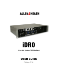
iDR10
iLive System DSP MixRack
USER GUIDE
Publication AP6525
Limited Two Year Warranty
This product has been manufactured in the UK by ALLEN & HEATH and
is warranted to be free from defects in materials or workmanship for a
period of two years from the date of purchase by the original owner.
To ensure a high level of performance and reliability for which this
equipment has been designed and manufactured, read this User Guide
before operating.
In the event of a failure, notify and return the defective unit to ALLEN &
HEATH or its authorised agent as soon as possible for repair under
warranty subject to the following conditions:
Conditions Of Warranty
1. The equipment has been installed and operated in accordance with
the instructions in this User Guide
2. The equipment has not been subject to misuse either intended or
accidental, neglect, or alteration other than as described in the User
Guide or Service Manual, or approved by ALLEN & HEATH.
3. Any necessary adjustment, alteration or repair has been carried out
by ALLEN & HEATH or its authorised agent.
4. The defective unit is to be returned carriage prepaid to ALLEN &
HEATH or its authorised agent with proof of purchase.
5. Units returned should be packed to avoid transit damage.
In certain territories the terms may vary. Check with your ALLEN &
HEATH agent for any additional warranty, which may apply.
This product complies with the European Electromagnetic
Compatibility directives 89/336/EEC & 92/31/EEC and the
European Low Voltage Directives 73/23/EEC & 93/68/EEC.
Any changes or modifications to the power supply unit not approved
by Allen & Heath could void the compliance of the product and
therefore the users authority to operate it.
iDR10 User Guide AP6525 Issue 1.
Copyright © 2008 Allen & Heath. All rights reserved
Manufactured in the United Kingdom by Allen & Heath Limited
Kernick Industrial Estate, Penryn, Cornwall, TR10 9LU, UK
http://www.allen-heath.com
2
iDR10 User Guide
Important Safety Instructions
WARNINGS
- Read the following before proceeding :
CAUTION
ATTENTION: RISQUE DE CHOC ELECTRIQUE – NE PAS OUVRIR
Read instructions:
Retain these safety and operating instructions for future reference. Adhere to
all warnings printed here and on the equipment. Follow the operating
instructions printed in this User Guide.
Do not remove covers:
Operate the equipment with its covers correctly fitted. Refer any service work
on the equipment to competent technical personnel only.
Power sources:
Connect the equipment to a mains power supply only of the type described
in this User Guide and marked on the rear panel. Use only the power cord
with sealed mains plug appropriate for your local mains supply as provided
with the equipment. If the provided plug does not fit into your outlet consult
your service agent for assistance.
Power cord routing:
Route the power cord so that it is not likely to be walked on, stretched or
pinched by items placed upon or against it.
Grounding:
Do not defeat the grounding and polarisation means of the power cord plug.
Do not remove or tamper with the ground connection in the power cord.
WARNING: This equipment must be earthed.
Water and moisture:
To reduce the risk of fire or electric shock do not expose the equipment to
rain or moisture or use it in damp or wet conditions. Do not place containers
of liquid on it which might spill into any openings.
Ventilation:
Do not obstruct the ventilation slots or position the equipment where the air
flow required for ventilation is impeded. If the equipment is to be operated in
a flightcase ensure that it is constructed to allow adequate ventilation.
Heat and vibration:
Do not locate the equipment in a place subject to excessive heat or direct
sunlight as this could be a fire hazard. Locate the equipment away from any
devices which produce heat or cause excessive vibration.
Servicing:
Switch off the equipment and unplug the power cord immediately if it is
exposed to moisture, spilled liquid, objects fallen into the openings, the
power cord or plug become damaged, during lightening storms, or if smoke,
odour or noise is noticed. Refer servicing to qualified technical personnel
only.
Installation:
Install the equipment in accordance with the instructions printed in this User
Guide. Use the equipment connections for their intended purpose only.
iDR10 User Guide
3
Important Mains plug wiring instructions.
The unit is supplied with a moulded mains plug fitted to the AC mains
power lead. Follow the instructions below if the mains plug has to be
replaced.
The wires in the mains lead are coloured in accordance with the
following code:
WIRE COLOUR
TERMINAL
European
USA/Canada
L
LIVE
BROWN
BLACK
N
NEUTRAL
BLUE
WHITE
E
EARTH GND
GREEN & YELLOW
GREEN
The wire which is coloured Green and Yellow must be connected to
the terminal in the plug which is marked with the letter E or with the
Earth symbol. This appliance must be earthed.
The wire which is coloured Blue must be connected to the terminal in
the plug which is marked with the letter N.
The wire which is coloured Brown must be connected to the terminal
in the plug which is marked with the letter L.
Ensure that these colour codes are followed carefully in the event of
the plug being changed.
Precautions
4
Damage :
To prevent damage to the equipment cosmetics, avoid placing heavy
objects on the unit, scratching the surface with sharp objects, or
subjecting the unit to rough handling and vibration.
Environment :
Protect from excessive dirt, dust, heat and vibration when operating
and storing. Avoid tobacco ash, smoke, drinks spillage, and
exposure to rain and moisture. If the equipment becomes wet, switch
off and remove power immediately. Allow to dry out thoroughly
before using again.
Cleaning :
Avoid the use of chemicals, abrasives or solvents. The equipment is
best cleaned with a soft brush and dry lint-free cloth. If the ventilation
grilles become blocked with dust use a vacuum cleaner to suck the
dirt out. Do not remove the cover to clean the unit.
Transporting :
The equipment should be transported in the original packing or
purpose built flightcase to protect it from damage during transit.
Cables:
Plan the location of the equipment so that the connecting cables are
not fully extended. Full extension of the cables can stress the
equipment and cables and may result in undesired performance.
Ensure that the cables are located such that they cannot be stood on
or tripped over.
Modules:
Do not remove the modules from the unit while power is applied.
iDR10 User Guide
Introduction
This is the user guide for the Allen & Heath iDR10 ‘MixRack’. We recommend that you
read this fully before starting. Included is information on installing, connecting and
operating the unit. Whilst we believe the information in this guide to be reliable we do
not assume responsibility for inaccuracies. We also reserve the right to make changes in
the interest of further product development.
We are able to offer further product support through our worldwide network of approved
dealers and service agents. You can also access our Web site (www.allen-heath.com)
for information on our company and its pedigree, our full product range and our design
philosophy. To help us provide the most efficient service please keep a record of your
unit serial number, and date and place of purchase to be quoted in any communication
regarding this product. The serial number is located on the rear panel.
For further information on using the iLive system please refer to:
iLive System Reference guide
AP6526
iLive Getting Started Guide
AP7260
Allen & Heath Resource CD
AP4742
Allen & Heath web site
www.allen-heath.com
Firmware Release Notes
Downloadable from web site
Help file within system firmware
Check the packing contents
Retain the product packing should you need to ship the product in future. You should find the
following components:
ALLEN&HEATH
iDR-64
MIX ENGINE
1x iDR10 MixRack. Depending on the order
configuration, the MixRack is either shipped
in a carton or a touring grade, shock
mounted flightcase.
1x MODULE EXTRACTOR TOOL AA6869.
This is fitted in clips at the rear of the
flightcase or packed in the carton.
1x IEC MAINS LEAD with moulded plug. Check that the plug
is suitable for connection to your local mains supply.
iDR10/n where n = mains voltage 120 (USA), 220 (EU), 240
(UK)
1x CAT5 CABLE 1.8m RJ45 EtherCon connections.
Part number AH7001. Connects the iDR10 to the iLive
Surface or another MixRack. Note that the second cable
required is shipped with the iLive Surface.
DOCUMENTATION including the User Guide AP6525, Safety
Sheet AP3345, Registration Card AP3594, and sticker
AP4943.
iDR10 User Guide
5
Welcome to the iDR10 MixRack
The iDR10 is the heart of the iLive mixing system. It is called the ‘MixRack’ as it houses the iDR-64
DSP mix engine, the CPU module which manages and allows remote control of the mix functions,
and the RAB (remote audio) module which provides up to two audio networking interfaces (currently
both EtherSound). It is the mixer itself, configurable and controllable via Ethernet using an iLive
Surface or PC. It is called the iDR10 because it includes 10 additional slot positions to fit the required
combination of audio input and output modules. This means the MixRack may be positioned on
stage near its sources and controlled remotely from up to 100 metres away using a control surface
connected via a CAT5 cable. Local audio required at the mix position can be transported to and from
the MixRack via a second CAT5 cable, therefore doing away with the need for a bulky traditional
copper multicore snake. Audio may be further distributed around the venue using the EtherSound
audio networks. Systems may be linked for split FOH/Monitor/Recording applications using
EtherSound as a digital mic splitter.
The iDR10 features a 64 input x 32 mix bus architecture with full processing on all input and mix
channels. You do not need to allocate or share processing. The iDR-64 ‘Rack Extra’ module
provides enough DSP for all the channel processing to be available all the time, together with 8
stereo internal effects devices. Input processing includes high-pass filter, noise gate, parametric EQ,
compressor, limiter/de-esser and delay. Mix processing includes both parametric and graphic EQ,
compressor, limiter and delay. The module is called ‘RackExtra’ because it includes a virtual 8 slot
rack which can be loaded with up to 8 additional processors from a library of many emulations of
high quality effects devices. The effects can add an extra 8 ‘short returns’ complete with parametric
EQ bringing the total number of sources feeding the mix to 72.
The user has a choice of input and output modules to fit into the 10 available MixRack card slots.
The same module types may be loaded into the 4 slots available at the rear of the iLive surface.
Unused slots may have blanking plates fitted. Each module handles 8 signals, either inputs or
outputs. These modules may be fitted anywhere within the available MixRack and Surface card slots.
Choices currently available include analogue mic/line inputs, XLR line out, and digital inputs and
outputs with a variety of optional formats including SPDIF, optical, AES, ADAT and more.
The iDR10 does away with the need for cumbersome outboard processing and I/O racks letting you
configure a full spec mix system in a compact footprint comprising just the MixRack and Surface. If,
however, you wish to insert favourite outboard devices you can do this by configuring any number of
channel and mix inserts patched to sockets anywhere in the system. Virtual patchbays are provided
too letting you map any input source to any channel, and any output signal to any socket.
The RAB module provides a local headphones output, the networked audio options and digital clock
source if synchronisation with external devices is required. Up to 2 EtherSound network card options
may be fitted to transport audio to and from locations remote from the MixRack. ESA replaces the
traditional analogue multicore providing audio at the surface and distributed to other EtherSound
equipped break in/out boxes. ESB provides a digital mic splitter for FOH/Monitor systems, multitrack
recording and system expansion.
The CPU module allows TCP/IP over Ethernet control from network devices such as the iLive Surface
or PC running iLive application software. A 3-port switcher is built in for control from multiple devices
accessing the same network, for example both a Surface and a laptop. The module also allows
control via MIDI and PL-Anet for the Allen & Heath PL Series remote controllers.
The iDR10 is well equipped for the stage environment with a lamp socket for low lighting conditions,
LED status indicators for phantom power, mute and PAFL active, ideal for helping the stage tech find
the right socket. The MixRack may be shipped in a touring grade, shock mounted flight case, and be
configured to include two internal universal voltage power supply modules, one for redundant supply
backup. Full protection and thermal management is provided.
Sound quality has been one of the key objectives behind the design of the iLive system. The
architectural design and choice of components ensure a high performance, very low latency system.
DSP algorithms developed by Allen & Heath over many years have been tailored for the demands of
live sound. The iDR10 uses a top of the range preamp design and features very high headroom
throughout the signal path to cope with the busiest and most dynamic live mix.
Please take the time to read through the rest of this guide before starting. Also refer to the iLive
System Reference Guide which has more information of configuring and using the iLive system.
6
iDR10 User Guide
DSP ‘RackExtra’ module
The DSP mix engine, the heart
of the iLive mixing system.
64x32 mix architecture plus 8x
internal FX racks.
REMOTE AUDIO module
With system clock, headphones
and remote audio distribution. Fit
up to 2 audio network option
cards. EtherSound interface is
available here.
iDR10
CPU module
Manages
the
MixRack
system and allows remote
control via Ethernet, MIDI
and PL-Anet. Also provides
System
modules
Slots K, L, M
MixRack
Ethernet switch
3x network ports.
ESA
EtherSound digital
snake.
Surface
and break out/in
audio.
ESB
EtherSound digital
mic split, system
expansion, record.
Audio modules
10 slots available.
Slots A to J
MIC/LINE IN module
8x mic preamps with remote
gain control.
LINE OUT module
8x balanced line out sockets.
PL-Anet
Connect to Allen &
Heath PL-Series
remote controllers.
DUAL MIC/LINE IN module
Connect 16x inputs on screw
terminal plugs.
8x mic
preamps each with remote
selection of A and B inputs.
Note:
You can choose any combination of input, output and blank
modules to load into the 10 available slots. The format above shows all
the options available at the time of print and is not representative of a
typical user setup. The photo below shows a popular configuration with
48 mic inputs and 24 line outputs loaded. Further inputs and outputs
would typically be available at the rear of the surface.
MULTI DIGITAL OUT module
16x outputs in digital format. ADAT, Aviom,
HearBack, iDR Expander. Uses 2 slots.
DIGITAL OUT module
4x pairs of digital outputs simultaneously
available AES, SPDIF or OPTO.
DIGITAL IN module
4x pairs of digital inputs selectable
either AES, SPDIF or OPTO.
FLIGHT CASE
Touring grade case on
wheels. Shock mounted
rack.
Front and rear
covers.
Module extractor tool
To help pull out modules if you
need to reconfigure the module
format.
Note: Do not remove or plug
in modules while power is
applied. The iLive system is not
‘hot pluggable’.
iDR10 User Guide
POWER SUPPLY module
Universal mains input.
One
required. Fit second as redundant
supply backup.
7
Installation
Free standing
The iDR10 can be operated as a freestanding unit for shelf or floor operation. Ensure adequate air
flow around the unit. It must not be covered in any way. Always stand the unit on a firm flat surface
away from any soft furnishings or carpet.
Rack mounting
The iDR10 is designed as a 19 inch rack mount unit and will occupy 9U of rack space. Ensure
natural convection of airflow around the unit by allowing good ventilation below, in front of and
behind the unit. Rack equipment known to produce a significant amount of heat should not be
mounted directly below the unit. Forced convection by means of a rack mounted fan-tray may be
desirable in situations where space is restricted and the ambient air temperature is high.
Flight casing
The iDR10 may be ordered with a suitable touring grade flight case. If you have a case made we
recommend that you use only a professional grade specification with shock mounted internal rack
frame. Ensure adequate ventilation in front of and behind the unit when it is powered. Make sure the
wheel locks are engaged when the unit is stationary.
Cables
Make sure the cables are not stretched in any way and are routed to avoid becoming kinked or
damaged. Allow enough service loop for access and removal of the unit. Ensure all connectors are
fully plugged in and locked.
ALLEN&HEATH
iDR-64
MIX ENGINE
SIDE
FRONT
350 mm / 13.8"
400 mm / 15.75" 9U
Dimensions and weights
482 mm / 19"
MIXRACK WEIGHT = 26kg / 57lb
643 mm / 25.3"
730 mm / 28.75"
669 mm / 26.34"
142 mm / 5.6"
ALLEN HEATH
Do not obstruct the ventilation
slots.
Ensure adequate air flow
around the iDR10.
Ensure proper grounding. Do
not remove the IEC mains cord earth
(ground) connection.
MIXRACK IN FLIGHTCASE = 68kg / 150lb
MIXRACK IN CARTON = 27kg / 60lb
8
iDR10 User Guide
Connecting the system
The iDR10 requires two main system connections, both using CAT5 cables. NETWORK connects a
remote controller such as the iLive Surface or a laptop. ESA connects audio to and from external
locations such as the Surface and EtherSound equipped break in/out boxes. The optional ESB port
can be used to connect audio between systems such as FOH/Monitor, broadcast or recording. iLive
systems are shipped with 1.8 metre UTP CAT5 cables fitted with EtherCon locking connectors as
standard. Allen & Heath can supply an 80 meter drum of approved cable (part number AH7000) if the
Surface is located remote from the MixRack. Two of these are required to connect control and audio
between the MixRack and the Surface. One is required to connect audio between the MixRack and
another remote rack.
Ethernet (control network) cable
A 3 port Ethernet switch is built into the CPU module allowing connection of more than one control
device, for example a Surface and a laptop. Cables up to 100 metres (330 feet) may be used. Plug
the CAT5 cable into any NETWORK port. Standard Ethernet hardware may be used to extend or
route this connection if required.
Note: Plug only one CAT5 cable to connect between the MixRack and Surface. You may plug this
into any one of the three network ports available. Do not connect a second cable for redundancy.
Third party systems are available to extend the connection or provide dual redundancy.
EtherSound (audio network) cable
Plug the MixRack ESA OUT to the Surface ESA IN to connect the PAFL, talkback and rear panel
input/output signals (ES channels 1 to 32) to and from the Surface. Plug the Surface ESA OUT to
external break in/out device ES IN to route signals to and from further locations if required (ES
channels 33 to 62). For information on using the optional ESB network refer to the panel descriptions
and application diagrams later in this user guide.
Note: Connect only one EtherSound cable between two devices. Do not connect both IN to OUT
and OUT to IN. The terminology ‘IN’ and ‘OUT’ refers to the clock master and not direction of audio.
Each EtherSound cable carries 64 channels of audio in both directions.
Note: The EtherSound standard is maintained and licensed by Digigram who recommend that only
the cable types and network components tested and approved for EtherSound are used. This is
most important to ensure reliability when using longer cable lengths approaching the 100 metre (330
feet) maximum. For further information on compatibility please refer to the EtherSound web site:
www.ethersound.com/technology/compatibility.php.
NETWORK
ESA IN
CPU
RAB
Connect RACK ESA OUT to SURFACE ESA IN
CONTROL (ETHERNET)
AUDIO (ETHERSOUND)
NETWORK
ESA OUT
ESB OUT
ETHERSOUND MIC SPLIT / SYSTEM EXPAND
iDR10 User Guide
9
Power up the system
Connect mains power
An IEC mains power cord with moulded plug suitable for
your territory is provided for each power supply module fitted
to the iDR10. Refer to your Allen & Heath agent if the
incorrect type has been provided. The iDR10 uses universal
voltage power supplies that accept world wide mains
sources from 100 to 240V.AC 47 to 63Hz. Make sure the IEC
plugs are pressed fully into their panel sockets and the
cables are clipped into the retaining clips to protect them
from accidental disconnection.
Note:
To ensure operator safety, connect only to an
approved and properly grounded mains source. Do not
remove the ground connection in the mains cord.
Note:
Read and understand the warnings in the safety
sheet supplied with the iDR10 and printed on the power unit
panel.
Note: It is good practice to connect both the MixRack and
the Surface to the same mains power ring or feed, and to use
a UPS (uninterruptible power supply) as a backup in critical
applications where there is any risk of mains or generator
power being interrupted.
MAINS FUSE - In the event of a fuse failure replace only
with the correct type and rating as indicated on the rear
panel. If the replacement fuse fails again, switch off and refer
to your Allen & Heath service agent.
ON/OFF switch - Press to toggle mains power on or off.
Booting up the system
Note: Always turn the MixRack on first, then the iLive Surface. Powering the
Surface up first may result in failure to connect or loss of EtherSound audio at the
surface. Power off the surface before turning off the MixRack.
1. Connect mains power.
2. Plug in the Control and Audio CAT5 cables.
3. Switch on the MixRack power.
4. Then switch on the Surface power.
While searching for the network connection between the MixRack and Surface after
power up, the NETWORK Lnk/Act indicator flashes at a slow rate for a few seconds.
Once connection is successfully made the indicator flashes at a steady fast rate. The
ES RX and TX indicators should flash at a steady fast rate soon after boot up.
The MixRack and Surface audio outputs are isolated from the connected equipment
during boot up using protection relays to prevent power up thumps. The connector
MUTE indicators light while the outputs are isolated. After around 15 seconds the
relays switch in and audio is presented to the outputs with the settings as they were
the last time the system was powered down.
The iLive system remembers its last settings on power up.
Note: For firmware versions up to 1.2 it is necessary to reboot the surface if the
network connection has become lost or its cable disconnected. To reboot the
surface switch its mains power off then on.
10
iDR10 User Guide
Module options – Analogue inputs and outputs
MIC/LINE INPUT part M-MICIN-A
This is the main audio input module for the iLive
system. It provides 8x high performance analogue
input preamps for microphone and line level signals.
The front end gain, pad and phantom power are
remote controlled via the network connection from
the Surface or PC. The settings may be recalled as
part of the iLive system memories.
CHK Yellow indicator follows the PAFL function. It
lights when the channel it is associated with is
currently being PAFL’d at the surface or PC. This
provides a quick way to identify which sockets are
mapped to the channels, for example when the FOH
engineer wants to indicate to the stage tech which
connection to check.
Note: CHK will light whether the preamp is the main
channel source, insert return or mix external input for
the channel being PAFL’d. For example, four may
be lit if you PAFL a stereo input channel which has
an insert assigned.
PP Lights when phantom power voltage is detected
at the XLR input socket. This will light whether the
voltage is sourced internally from within the MixRack,
or externally via the cable plugged in.
INPUT XLR Balanced audio input with wide gain
range accepting signals from -65dBu to +30dBu.
Gain is remote controlled and has a 1dB resolution
and range of 80dB including 25dB pad.
The
preamps feed the iLive mix engine through 24bit, low
noise, low latency converters. The preamp gain is
automatically set for +4dBu or -10dBV operating
level if assigned as an insert.
DUAL MIC/LINE INPUT part M-DUALIN-A
An 8 channel input module to connect up to 16
microphone or line level signals. As described
above but with remote controlled selection between
two inputs A or B per channel. Connection is via
screw terminal Phoenix plugs (supplied), ideal for
installed applications or where external stage boxes
are used. The green indicator lights when the B
input is selected.
Analogue LINE OUTPUT part M-LINEOUT-A
8x Balanced line level outputs operating at +4dBu
and with +22dBu maximum output. Any signal
whether a mix output, direct output, insert send or
MixRack input may be assigned to any socket.
CHK Lights when the socket is associated with a
channel currently being PAFL’d, whether an output
or insert send.
MUTE A red LED lights when the output is muted.
Note: The line outputs are relay switched to protect
speaker systems from power on/off thumps.
iDR10 User Guide
11
Module options – Digital inputs and outputs
DIGITAL INPUT part M-DIGIN-A
This module provides 8 digital inputs arranged as
four pairs. Each offers a choice of digital format AES, SPDIF or optical (TOSLINK). For each pair,
one format is chosen and used at a time. The
selection is made using the iLive Surface or PC
application channel SEL function. One of 3 yellow
LED indicators lights to show which input format is
selected.
Blanking plugs are provided for unused optical
sockets to prevent interference and dust
contamination.
CHK Yellow indicator follows the PAFL function. It
lights when one or both channels of the input are
associated with the channel currently being PAFL’d
at the surface or PC. This provides a quick way to
identify which sockets are mapped to the channels,
for example when you want to quickly find which
sockets to plug your digital playback device into.
Note: CHK will light whether the input is the main
channel source, insert return or mix external input for
the channel or mix being PAFL’d. For example, three
may be lit if you PAFL a stereo input channel which
has an insert assigned.
DIGITAL OUTPUT part M-DIGOUT-A
Provides 8 digital outputs arranged as four pairs.
Each offers 3 digital output formats – AES, SPDIF
and optical (TOSLINK).
All three formats are
available at the same time. For example, you could
record the same material via SPDIF and also AES to
two different recording devices at the same time.
Blanking plugs are provided to prevent dust
contamination and light spill from unused optical
sockets.
CHK Yellow indicator follows the PAFL function. It
lights when one or both channels of the output are
associated with the channel currently being PAFL’d
at the surface or PC. This provides a quick way to
identify which sockets are mapped to the channels,
for example when you want to quickly find which
sockets to feed your digital recording device.
Note: CHK will light whether the socket is the main
mix output or an insert send. For example, three
may be lit if you PAFL a stereo mix which has an
insert assigned.
MUTE A red LED lights when an output is muted.
12
iDR10 User Guide
Module options – Digital outputs
DIGITAL MULTI OUT part M-MULTI-OUT-A
This module provides 16 outputs and therefore uses
two slots at the MixRack or Surface. Use the iLive
OUTPUTS patch bay to map any signal to any output
socket.
The module presents these outputs
simultaneously to a variety of different multi-channel
digital formats:
ADAT
There are two ADAT optical light pipe
outputs, each carrying 8 audio channels. Use these
to connect to ADAT equipped devices such as
multitrack recorders.
Note:
One module allows up to 16 tracks of
recording. Fit two for 24 or 32 tracks. Note that you
can fit only one MULTI OUT module to the iLive
Surface in slots A and B. This provides up to 16
tracks at the surface. For multitrack recording up to
64 tracks consider using a PC fitted with the optional
Digigram LX6464ES EtherSound PCI card interfaced
to the MixRack via the ESB option. For more
information see www.digigram.com/products/
iDR Expander
Two 8 channel proprietary iDR
expander ports are provided. Connect these to Allen
& Heath iDR output expander units (part of the iDR
installation range) for remote analogue balanced
XLR line outputs up to 300 metres (900 feet) away
using two CAT5 cables per unit. The DR-LINK cables
carry the control to these units.
AVIOM An Aviom compatible interface is provided
to feed the 16 channels of an Aviom personal
monitor mixing system, popular with many live
mixing installations such as houses of worship.
Connect OUT to the Aviom system using a CAT5
cable. IN allows expansion to add another 16
external signals to the feed.
Signals may be
configured for mono or stereo operation within the
iLive operating system. For more information about
the Aviom system see web site www.aviom.com/
HearBus OUT The module also supports the Hear
Technologies Hear Back personal monitoring system
which distributes up to 8 signals using a single CAT5
cable. For more information see web site
www.heartechnologies.com/hb/hearbackintro.htm
CHK Yellow indicator follows the PAFL function. It
lights when the signal associated with the output is
currently being PAFL’d at the surface or PC. This
provides a quick way to check the socket patching,
for example to identify which signals are feeding
each channel of a personal monitoring system.
MUTE A red LED lights when the output is muted.
iDR10 User Guide
13
Module options - System
iDR-64 RackExtra DSP
This is the DSP mix engine, the ‘brains’ of the iLive
system.
The DSP (Digital Signal Processing)
handles the audio signal processing such as EQ,
dynamics, delays and mixing. The more recent
‘RackExtra’ version includes additional DSP to
handle up to 8 internal stereo effects ‘racks’. Older
systems with 2 effects may be upgraded to this
version by swapping out the iDR-64 DSP module.
Note: The DSP is in the MixRack not the Surface.
Audio in the Surface is converted to digital and
transported via EtherSound to the MixRack where it
is processed by the iDR-64 RackExtra module. The
surface cannot be used as a stand alone mixer
without the iDR10 or iDR0 rack which houses this
module.
REMOTE AUDIO (RAB) part M-RAB-B, C or D
Handles the audio clock, headphones signal and
interface for up to two digital audio networks.
HEADPHONES
A built-in headphones amplifier
with volume control and ¼” output socket lets you
listen to the signal currently selected using the PAFL
function. This is the same signal presented to the
Surface headphones / local monitor system.
SYSTEM LOCK The yellow LED lights to indicate
digital audio sync lock. If it is not lit check that the
correct system Audio Clock Source is selected.
Setting audio clock source (Surface TouchScreen
MIXRACK / Mixer Pref / Audio Sync) If the iDR10 is
part of a single rack system, or the master in a linked
FOH/Monitor system then set the Clock Source to
‘Internal’. If it is the slave getting its channel preamp
sources via EtherSound network ESB then set it to
‘ESB’. If it is being synchronized to an external
DARS source then set it to ‘DARS’.
ESA and ESB audio network options - The iDR10
may be ordered with none, one or both EtherSound
option cards fitted:
Part M-RAB-B
Part M-RAB-C
Part M-RAB-D
1x ES (ESA)
no ES
2x ES (ESA and ESB)
Use ESA to transport audio to and from the iLive
Surface and/or other EtherSound equipped devices
such as break out / break in boxes and speaker
controllers. Use ESB to transport audio between iDR
racks and other EtherSound equipped devices such
as the Digigram LX6464 PCI multitrack recording
card.
Note: With no ES option fitted you can still connect
the PAFL monitor and talkback signals to the iLive
Surface using analogue connections.
14
iDR10 User Guide
Module options - System
Restore the factory default mapping of ESA if it has been previously changed for
other EtherSound applications using an external PC running the Auvitran ES Monitor
or similar software. This automatically reboots the iLive system, reconfiguring
(restoring) the current I/O setting assignments.
Set the system audio clock
source to Internal, ESB or
DARS sync input.
Note:
Refer to the iLive
System Reference Guide for
more
information
on
EtherSound and how to
configure it.
Refer to the diagrams later in
this guide for applications
using EtherSound
Setting
the
ESB
Configuration
(Surface
TouchScreen MIXRACK / Mixer Pref / Audio Sync)
This screen lets you configure the iDR10 to be the
ESB master or slave. If you are using ESB to provide
audio to another system then set it as MASTER. If
you are receiving the channel audio from another
system then set it as MASTER/SLAVE.
NETWORK
ESA IN
Surface
CPU
RAB
Connect RACK ESA OUT to SURFACE ESA IN
iDR10
NETWORK
ESA OUT
ESB OUT
ETHERSOUND MIC SPLIT / SYSTEM EXPAND
ESB IN
iDR0
ES IN and OUT - Plug a single CAT5 cable to
connect audio between EtherSound equipped
devices. Plug into the OUT socket on whichever
device is the audio clock master or is in the chain
nearest to it. Plug into the IN socket on the slave
device. For example, plug iDR10 ESA OUT to
Surface ESA IN.
Correct EtherSound data traffic is indicated by the
steady flashing of both the RX and TX LEDs. If
neither or just one is flashing then check for correct
connection or a cable fault. The ES connection is
made as soon as the cable is plugged in.
Note: Only one cable is required to connect the
audio to and from the remote device. Connect OUT
on the master device to IN on the slave device. This
refers to the clock master, not audio direction. Do
not connect OUT to IN and IN to OUT using two
cables.
DARS IN and OUT - This lets you synchronize the
iDR10 audio clock to an external device, or
synchronize the external device to the iDR10 audio
clock using the AES Digital Audio Reference System.
iDR10 User Guide
15
Module options - System
CPU module
Provides the control interface to the MixRack. This
module is identified as the ‘iDR RACK CPU’. It is not
interchangeable with the iLive Surface CPU module.
Power ON Blue LEDs display the power supply
status. One or two power supply modules may be
fitted to the MixRack. The second provides dual
supply redundancy.
12V LAMP Plug in a standard 4-pin XLR gooseneck
console lamp to illuminate the rack while plugging
up in a dark environment. We recommend you use
the Allen & Heath LEDlamp with long life white LED
bulbs and built-in dimmer.
NETWORK A 3 port Ethernet switch is built in. This
lets you connect several network devices to the
iDR10, for example an iLive Surface and a laptop
running the iLive application software. The yellow
Lnk/Act indicators flash to indicate network data
activity.
Note: Do not connect more than one network cable
between two devices. Attempting to connect a
second cable as a ‘redundant backup’ will result in
loss of control.
Note: When using firmware versions up to V1.2,
disconnection of the network cable or loss of
network connection requires a Surface reboot.
Reset A recessed switch lets you reset the network
address and settings to factory default. This is useful
if you are using a MixRack and a Surface with
unknown network addresses or which had different
addresses previously set. Resetting each networked
device (MixRack, Surface and TouchScreen) will
ensure the devices connect correctly. To reset the
settings, press and hold the switch in using a
pointed object while powering up the rack. Keep the
switch pressed for at least 10 seconds while the rack
boots. Default settings are:
IP address 192.168.1.1
Subnet mask 255.255.255.0
Gateway 192.168.1.254
MIDI IN, THRU and OUT - Standard MIDI interface
for external system control using MIDI messages.
For more information refer to the iLive Reference
Guide and firmware version release notes.
PL-Anet - Proprietary RS485 based control port for
connecting Allen & Heath PL Series remote
controllers such as wall plates, GPIO and
fader/encoder panels. For more information refer to
the iLive Reference Guide, PL Series guides and
firmware release notes.
16
iDR10 User Guide
Using the iDR10
There are several ways the iDR10 can be used within an iLive system. It is one of many component
options that may be configured to satisfy a host of demanding audio mixing applications. We
recommend that you visit the Allen & Heath web site for information on the full range of iLive
components available. You can also download additional application drawings which illustrate the
versatility of iLive in satisfying many basic and advanced applications.
Refer also to the iLive Getting Started Guide AP7260 and the iLive System Reference Guide AP6526.
Further information on the latest features is available in the Release Notes which come with each
firmware release. Check our web site to download the latest version of iLive firmware.
The following pages illustrate some of the iDR10 applications. They are based on preconfigured
‘template’ Show memories which can be recalled from the Surface UTILITY / Configuration / Show
Manager screen. They give you a good starting point by configuring a recognisable classic
architecture and surface layout. You can edit these and name and store your customised
configurations as User Shows.
APPLICATION EXAMPLE - STANDARD SINGLE RACK SYSTEM
64 inputs, 32 mixes, 8 effects.
1
iLive
FOH_8fx_LR
Load Show
FOH
NETWORK
ESA IN
A
B
C
HEADPHONES and TALKBACK
D
ETHERNET
CAT5
ETHERSOUND
CAT5
FOH LOCAL AUDIO
A1-8 = CH 57-64
C1-2 = AUX7-8
C3-4 = ST AUX1
C5-8 = MAIN
D1-4 = MTX1-4
D5-8 = ST MTX1-2
2 x CAT5 cables to stage
iDR10
ALLEN&HEATH
iDR-64
AUDIO CLOCK = INTERNAL
A
B
C
D
E
F
G
STAGE INPUTS
A1-G8 = I/P 1-56
ESB CONFIG = MASTER
CH SOURCE = LOCAL INPUTS
Set options using TOUCHSCREEN = MIXRACK / Mixer Pref / Audio Sync Networks
iDR10 User Guide
ESA OUT
MIX ENGINE
CONFIG
8x GRP = 4m 2st
18x AUX = 8m 1st 8FX
MAIN = LR
8x MTX = 4m 2st
NETWORK
H
I
J
STAGE OUTPUTS
H1-8 = AUX1-8
I1-2 = ST AUX1
I3-4 = I5-8 = MAIN1-4
J1-4 = MTX1-4
J5-6 = ST MTX1-2
17
APPLICATION EXAMPLE - FOH / MONITOR (Analogue mic splitter)
56 inputs FOH, 48 way split. Each engineer has gain control.
2
FOH_8fx_LR
Load Show
iLive
Each engineer has their own preamp (gain) control
FOH
NETWORK
ESA IN
A
B
C
HEADPHONES and TALKBACK
D
ETHERNET
CAT5
ETHERSOUND
CAT5
FOH LOCAL AUDIO
C1-2 = AUX7-8
C3-4 = ST AUX1
C5-8 = MAIN
D1-4 = MTX1-4
D5-8 = ST MTX1-2
2 x CAT5 cables to stage
Load Show
A1-8 = CH 57-64
MON_2fx_8m8st
MONITORS
NETWORK
ESA IN
A
B
C
D
LOCAL AUDIO
A1-8 = CH57-64
HEADPHONES / IEM
CAT5
ENGINEER'S WEDGE
Set options using TOUCHSCREEN = MIXRACK / Mixer Pref / Audio Sync Networks
AUDIO CLOCK = INTERNAL
AUDIO CLOCK = INTERNAL
ESB CONFIG = MASTER
ESB CONFIG = MASTER
CH SOURCE = LOCAL INPUTS
CH SOURCE = LOCAL INPUTS
iDR10
iDR10
ALLEN&HEATH
ALLEN&HEATH
NETWORK
iDR-64
iDR-64
ESA OUT
NETWORK
ESA OUT
MIX ENGINE
MIX ENGINE
CONFIG
A
B
C
26x AUX = 8m 2st 2FX
A B
8x MTX = 4m 2st
CONFIG
MONITOR INPUTS MONITOR OUTPUTS
8x GRP = 4m 2st
A1-F8 = I/P 1-48
G1-8 = AUX1-8
18x AUX = 8m 1st 8FX
H1-8 = ST AUX1-4
MAIN = LR
I1-8 = ST AUX5-8
8x MTX = 4m 2st
J1-4 = MTX1-4
J5-6 = ST MTX1
J7-8 = PAFL OUT
D
E
F
G
H
I
J
C
D
E
F
G
H
FOH INPUTS
A1-F8 = I/P 1-48
I
J
FOH OUTPUTS
I1-2 = ST AUX1
I3-4 = I5-8 = MAIN1-4
J1-4 = MTX1-4
J5-6 = ST MTX1-2
MIC SPLITTER
MONITOR SPLIT
18
FOH SPLIT
iDR10 User Guide
APPLICATION EXAMPLE - FOH / MONITOR (Digital mic splitter)
56 inputs FOH, 48 way split. One engineer has gain control affecting both.
3
FOH_8fx_LR
Load Show
iLive
FOH engineer has control of preamp gain and phantom power
FOH
NETWORK
ESA IN
A
B
C
HEADPHONES and TALKBACK
D
ETHERNET
CAT5
ETHERSOUND
CAT5
FOH LOCAL AUDIO
C1-2 = AUX7-8
C3-4 = ST AUX1
C5-8 = MAIN
D1-4 = MTX1-4
D5-8 = ST MTX1-2
2 x CAT5 cables to stage
Load Show
A1-8 = CH 57-64
SLAVE_MON_8m8st
FOH gain affects monitors but engineer has digital channel trims
MONITORS
NETWORK
ESA IN
A
B
C
D
LOCAL AUDIO
A1-8 = CH57-64
HEADPHONES / IEM
CAT5
ENGINEER'S WEDGE
Set options using TOUCHSCREEN = MIXRACK / Mixer Pref / Audio Sync Networks
AUDIO CLOCK = ESB
AUDIO CLOCK = INTERNAL
ESB CONFIG = MASTER/SLAVE
ESB CONFIG = MASTER
CH SOURCE = ESB
CH SOURCE = LOCAL INPUTS
iDR10 (SLAVE)
iDR10
D
E
F
G
H
CONFIG
26x AUX = 8m 2st 2FX
8x MTX = 4m 2st
MONITOR INPUTS
A-F = BLANK
CH1-56 = ESB
iDR10 User Guide
I
ESA OUT
MIX ENGINE
MIX ENGINE
C
NETWORK
iDR-64
iDR-64
B
ALLEN&HEATH
ALLEN&HEATH
A
(MASTER)
ESB IN
J
MONITOR OUTPUTS
G1-8 = AUX1-8
H1-8 = ST AUX1-4
I1-8 = ST AUX5-8
J1-4 = MTX1-4
J5-6 = ST MTX1
J7-8 = PAFL OUT
A
B
C
CONFIG
8x GRP = 4m 2st
18x AUX = 8m 1st 8FX
MAIN = LR
8x MTX = 4m 2st
D
E
F
G
H
FOH INPUTS
A1-G8 = I/P 1-56
I
NETWORK
ESA OUT
ESB OUT
J
FOH OUTPUTS
I1-2 = ST AUX1
I3-4 = I5-8 = MAIN1-4
J1-4 = MTX1-4
J5-6 = ST MTX1-2
19
APPLICATION EXAMPLE - FOH / MONITOR (Digital mic splitter. No ESA at Monitor)
48 inputs FOH, 40 way split. One engineer has gain control affecting both.
4
FOH_8fx_LR
Load Show
iLive
FOH
FOH engineer has control of preamp gain and phantom power
NETWORK
ESA IN
A
B
C
HEADPHONES and TALKBACK
D
ETHERNET
CAT5
ETHERSOUND
CAT5
FOH LOCAL AUDIO
C1-2 = AUX7-8
C3-4 = ST AUX1
C5-8 = MAIN
D1-4 = MTX1-4
D5-8 = ST MTX1-2
2 x CAT5 cables to stage
Load Show
A1-8 = CH 57-64
SLAVE_MON_8m8st
FOH gain affects monitors but engineer has digital channel trims
MONITORS
No ESA fitted. No audio in surface because the rack is local.
Surface PAFL monitor and TALKBACK use analogue connections to the rack.
LOCAL MON OUT
PAFL IN
XLR CABLES
TALKBACK OUT (audio)
A
B
NETWORK
C
D
ETHERNET
CAT5
HEADPHONES / IEM
iDR10
CAT5
AUDIO CLOCK = ESB
AUDIO CLOCK = INTERNAL
ESB CONFIG = MASTER/SLAVE
ESB CONFIG = MASTER
CH SOURCE = ESB
CH SOURCE = LOCAL INPUTS
iDR10
(SLAVE)
(MASTER)
ALLEN&HEATH
ALLEN&HEATH
iDR-64
iDR-64
ESB IN
< DIGTAL MIC SPLITTER
B
C
D
E
F
G
LOCAL INPUTS
F1-F8 = I/P 41-48
TB uses INPUT 48
20
H
I
J
MONITOR SENDS
G1-8 = AUX1-8
H1-8 = ST AUX1-4
I1-8 = ST AUX5-8
J1-4 = MTX1-4
J5-6 = ST MTX1
J7-8 = PAFL OUT
MIX ENGINE
MIX ENGINE
A
A
B
C
CONFIG
8x GRP = 4m 2st
18x AUX = 8m 1st 8FX
MAIN = LR
8x MTX = 4m 2st
D
E
F
G
H
FOH INPUTS
A1-E8 = I/P 1-40
I
NETWORK
ESA OUT
ESB OUT
J
FOH OUTPUTS
I1-2 = ST AUX1
I3-4 = I5-8 = MAIN1-4
J1-4 = MTX1-4
J5-6 = ST MTX1-2
iDR10 User Guide
APPLICATION EXAMPLE - FOH / MONITOR (iDR0 at Monitors)
64 inputs FOH, 56 way split. FOH engineer has gain control.
6
FOH_8fx_LR
Load Show
iLive
FOH engineer has control of preamp gain and phantom power
FOH
NETWORK
ESA IN
A
B
C
HEADPHONES and TALKBACK
D
ETHERNET
CAT5
ETHERSOUND
CAT5
FOH LOCAL AUDIO
A1-8 = CH 57-64
D1-4 = MTX1-4
D5-8 = ST MTX1-2
2 x CAT5 cables to stage
Load Show
MONITORS
SLAVE_MON_8m8st
FOH gain affects monitors but engineer has digital channel trims
NETWORK
ESA IN
MONITOR AUDIO
C
A
A1-8 = CH57-64
B
B1-8 = AUX1-8
C1-8 = ST AUX1-4
D1-8 = ST AUX5-8
D
HEADPHONES / IEM
ENGINEER'S WEDGE
CAT5
iDR0 (SLAVE)
CAT5
iDR10 (MASTER)
ALLEN&HEATH
CONFIG
26x AUX = 8m 2st 2FX
iDR-64
< MIC SPLITTER (MIXRACK I/P 1-56)
MIX ENGINE
CONFIG
AUDIO CLOCK = ESB
ESB CONFIG = MASTER/SLAVE
CH SOURCE = GLOBAL ESB INPUT
8x GRP = 4m 2st
18x AUX = 8m 1st 8FX
MAIN = LR
8x MTX = 4m 2st
AUDIO CLOCK = INTERNAL
A
B
C
D
E
F
G
STAGE INPUTS
A1-G8 = I/P 1-56
ESB CONFIG = MASTER
CH SOURCE = LOCAL INPUTS
H
I
NETWORK
ESA OUT
ESB OUT
J
FOH PA SENDS
I1-2 = ST AUX 1
I3-4 = I5-8 = MAIN1-4
J1-4 = MTX1-4
J5-8 = ST MTX1-2
Set options using TOUCHSCREEN = MIXRACK / Mixer Pref / Audio Sync Networks
iDR10 User Guide
21
APPLICATION EXAMPLE - FOH / MONITOR (iDR0 at FOH)
64 inputs FOH, 56 way split. Monitor engineer has gain control.
7
Load Show
iLive
SLAVE_FOH_LR
Monitor gain affects FOH but engineer has channel digital trims
FOH
NETWORK
ESA IN
A
B
C
HEADPHONES and TALKBACK
CONFIG
D
ETHERNET
CAT5
8x GRP = 4m 2st
18x AUX = 8m 1st 8FX
MAIN = LR
8x MTX = 4m 2st
ETHERSOUND
CAT5
iDR0 (SLAVE)
FOH AUDIO
A1-8 = CH 57-64
C1-2 = AUX7-8
C3-4 = ST AUX1
C5-8 = MAIN1-4
D1-4 = MTX1-4
D5-8 = ST MTX1-2
ESA OUT
ESB IN
AUDIO CLOCK = ESB
ESB CONFIG = MASTER/SLAVE
Single CAT5 EtherSound cable to stage (no Ethernet connection)
CH SOURCE = GLOBAL ESB INPUT
Set options using TOUCHSCREEN = MIXRACK / Mixer Pref / Audio Sync Networks
Load Show
MON_2fx_8m8st
Monitor engineer has control of preamp gain and phantom power
MONITORS
NETWORK
ESA IN
MONITOR OUTPUTS
A1-4 = MTX1-4
A5-8 = ST MTX1-2
B1-8 = AUX1-8
C1-8 = ST AUX1-4
D1-8 = ST AUX5-8
A
B
C
D
ETHERNET
CAT5
HEADPHONES / IEM
iDR10 (MASTER)
ETHERSOUND
CAT5
ALLEN&HEATH
ESA OUT
ETHERSOUND
CAT5
ENGINEER'S WEDGE
iDR-64
ESB OUT
MIC SPLITTER (MIXRACK I/P 1-56) >
MIX ENGINE
AUDIO CLOCK = INTERNAL
A
B
C
D
E
F
G
STAGE INPUTS
A1-G8 = I/P 1-56
H
I
J
ESB CONFIG = MASTER
CH SOURCE = LOCAL INPUTS
CONFIG
26x AUX = 8m 2st 2FX
8x MTX = 4m 2st
22
iDR10 User Guide
APPLICATION EXAMPLE - FOH / MONITOR (iDR0 at FOH, No ESA on Monitor)
56 inputs FOH, 48 way split. No ESA on monitor system. Monitor engineer has gain control.
8
Load Show
iLive
SLAVE_FOH_LR
Monitor gain affects FOH but engineer has channel digital trims
FOH
NETWORK
ESA IN
A
B
C
HEADPHONES and TALKBACK
D
ETHERNET
CAT5
CONFIG
8x GRP = 4m 2st
18x AUX = 8m 1st 8FX
MAIN = LR
8x MTX = 4m 2st
ETHERSOUND
CAT5
iDR0 (SLAVE)
FOH AUDIO
ESA OUT
ESB IN
A1-8 = CH 57-64
C1-2 = AUX7-8
C3-4 = ST AUX1
C5-8 = MAIN1-4
D1-4 = MTX1-4
D5-8 = ST MTX1-2
AUDIO CLOCK = ESB
ESB CONFIG = MASTER/SLAVE
Single CAT5 EtherSound cable to stage (no Ethernet connection)
CH SOURCE = GLOBAL ESB INPUT
Set options using TOUCHSCREEN = MIXRACK / Mixer Pref / Audio Sync Networks
Load Show
MON_2fx_8m8st
Monitor engineer has control of preamp gain and phantom power
MONITORS
No ESA fitted. No audio in surface because the rack is local.
Surface PAFL monitor and TALKBACK use analogue connections to the rack.
LOCAL MON OUT
PAFL IN
XLR CABLES
TALKBACK OUT (audio)
A
B
NETWORK
C
D
ETHERNET
CAT5
HEADPHONES / IEM
iDR10 (MASTER)
ENGINEER'S WEDGE
ETHERSOUND
CAT5
ALLEN&HEATH
iDR-64
ESB OUT
MIC SPLITTER (MIXRACK I/P 1-48) >
MIX ENGINE
AUDIO CLOCK = INTERNAL
A
B
C
D
E
F
G
STAGE INPUTS
A1-F8 = I/P 1-48
TB uses INPUT 48
iDR10 User Guide
H
I
J
MONITOR SENDS
G1-8 = AUX1-8
H1-8 = ST AUX1-4
I1-8 = ST AUX5-8
J1-4 = MTX1-4
J5-6 = ST MTX1
J7-8 = PAFL OUT
ESB CONFIG = MASTER
CH SOURCE = LOCAL INPUTS
CONFIG
26x AUX = 8m 2st 2FX
8x MTX = 4m 2st
23
24
iDR10 User Guide