1
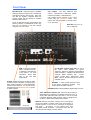
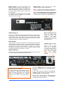
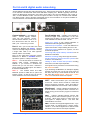
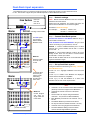
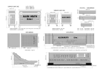
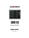
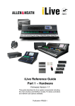
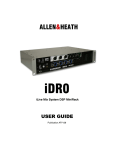
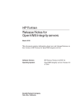
Fixed Format MixRacks iDR-16 iDR-32 iDR-48 iDR-64 Getting Started Guide Publication AP7445 Safety Instructions Before starting, read the Important Safety Instructions printed on the sheet supplied with the equipment. For your own safety and that of the operator, technical crew and performers, follow all instructions and heed all warnings printed on the sheet and on the equipment panels. System operating firmware The feature set of the iLive system is determined by the firmware (operating software) that runs it. Firmware is updated regularly as new features are added and improvements made, and is available for download from the Allen & Heath web site. This guide relates to Version 1.7 firmware. Some of the details shown in this guide may differ from those in the current release of firmware. Refer to the web site for the latest version and read the Release Notes that come with each version of firmware for further details. Note: Make sure all your iLive MixRacks and Surfaces are running the same version of firmware, and that the Editor software running on your laptop is compatible. This user guide This guide provides quick start information for the fixed format iLive Series iDR-16, iDR-32, iDR48 and iDR-64 MixRacks. The modular iDR10 and iDR0 MixRacks are referred to here but please see their user guides for further information about those models. The guides can be downloaded from the Allen & Heath web site. Further information For further information, refer to the user guides associated with each system component. Refer also to the iLive Fixed Format Systems Getting Started Guide AP7141. Use the HELP MANUAL available from the iLive Surface TouchScreen UTILITY menu and the Editor software. Refer to the Allen & Heath web site for the latest information on iLive and additional resources for download. IMPORTANT- Please read carefully By using this Allen & Heath product and the software within it, you agree to be bound by the terms of the relevant End User Licence Agreement (EULA), a copy of which can be found on the Allen & Heath website in the product's pages. You agree to be bound by the terms of the EULA by installing, copying, or otherwise using the software. iDR-16, 32, 48 and 64 MixRack Getting Started Guide AP7445 Issue 3 Copyright © 2010 Allen & Heath. All rights reserved ALLEN&HEATH Designed in the United Kingdom by Allen & Heath Limited, Kernick Industrial Estate, Penryn, Cornwall, TR10 9LU, UK http://www.allen-heath.com iDR MixRack Getting Started Guide 2 AP7445 iss.3 Introduction iLive is a state of the art system of components providing a uniquely flexible solution dedicated to live sound mixing and associated applications. It separates the mix engine from the control surface putting the audio and the DSP where it is needed near the stage, and offering a host of control and audio networking possibilities. Refer to the Allen & Heath web site to find out more about the iLive system. The MixRack is the heart of the system. It is the mixer itself complete with audio sockets, DSP to process the audio, and control and audio networking ports. The MixRack is typically connected to one of the many iLive Surfaces available, but can also be controlled at the same time as or even without a Surface using a laptop running the iLive Editor software, or preconfigured to run with PL Series remote controllers. Walking the stage with a wireless laptop or touch tablet opens up a whole new world of mixing… Distributed system – Separate MixRack (DSP) and Surface (controller) Network, wireless laptop, touch tablet control Editor software for online or offline PC/Mac control System can be run without a Surface using laptop only Choice of 6 MixRacks (DSP only, modular, 16, 32, 48, 64 mics) Mix and match any combination of MixRack and Surface Digital snake for local audio at the Surface – ACE™ single CAT5 up to 120m Port B audio network option for digital mic splitting and system linking Choose from ACE™, ES, MADI, ADAT, Aviom™ and more 64x32 RackExtra DSP engine with 8 stereo FX processors 32 buses can be configured as mono/stereo groups, auxes, mains, matrix Main mix types – none, M, LR, LCR, LCRplus, LRSub, LCRSub and more Unique Sub main mix mode for instant access to separate sub bass level Monitor mix capability with engineer’s Wedge and IEM monitors 64 channels configurable as mono or stereo Two MixRacks can be linked in Dual-Rack mode to provide 128 input channels Up to 72 sources to the mix including FX returns (136 in Dual-Rack mode) 3 Dynamics, PEQ, HPF and Delay on all 64 inputs 2 Dynamics, PEQ, 1/3 octave GEQ and Delay on all 32 mixes 8 Stereo FX with dedicated returns, PEQ and DFX Shaper FX emulations of popular industry standard devices Input, output and insert soft patchbays Up to 8 channel Gangs with choice of which parameters to link 16 DCAs with DCA or Mute Group mode Built-in signal generator and RTA User definable channel names and colours Libraries, Scenes and Show memories with USB transfer and Scene filter Firmware and memories compatible across all models Store all or selected items in Scene memories Get started quickly with built-in Template Shows 8 Password protectable User Profiles Compatible with Allen & Heath PL remote controllers and iDR Series MIDI interface at both the MixRack and Surface High performance, recallable mic/line preamps Digital +/-24dB Trim for FOH/Monitor gain sharing Low latency, low noise, very high preamp and mix headroom Relay protected outputs Redundant backup PSU capability iDR MixRack Getting Started Guide 3 AP7445 iss.3 iLive MixRack Range There are 6 versions of MixRack to choose from. All MixRacks feature the same powerful 64 channel x 32 mix bus, 8FX RackExtra DSP mix engine and have 64 channel bi-directional network capability. The main difference is the number of physical input and output sockets available. Choose the rack to suit your application and budget, whether the modular iDR10 for maximum I/O and flexibility, iDR0 with DSP only fed from digital mic split, or iDR-16, 32, 48 or 64 with different number of mic preamps and physical sockets. Regardless of size or number of sockets, all iLive MixRacks can work with the full 64 channels when additional sources are patched via the Port A (surface audio) and Port B (expander) networks. This means that even the smallest iDR-16 can be linked as the ‘slave’ in a large format dual FOH/Monitor system using digital mic split from the ‘master’ rack. iDR-16 The smallest stand alone MixRack ideal for compact applications mixing up to 16 mics, or FOH/Monitor systems with digital mic split. 3U fixed format MixRack 16 mic/line in, 8 XLR out ACE™ single CAT5 Surface link Port B network option slot External redundant supply option iDR-32 Equivalent to a 32 channel console. 6U fixed format MixRack 32 mic/line in, 16 XLR out ACE™ single CAT5 Surface link Port B network option slot External redundant supply option iDR-48 Equivalent to a 48 channel console. 8U fixed format MixRack 48 mic/line in, 24 XLR out ACE™ single CAT5 Surface link Port B network option slot External redundant supply option iDR-64 Equivalent to a 64 channel console. 9U fixed format MixRack 64 mic/line in, 32 XLR out ACE™ single CAT5 Surface link Port B network option slot External redundant supply option iDR10 Flagship MixRack with modular I/O and increased networking flexibility. 11U modular MixRack with RAB2 Up to 80 sockets, up to 64 mic/line in Wide range of I/O module options Port A Surface link option slot Port B network option slot Built-in redundant supply option 4-pin XLR lamp socket Optional flight case iDR0 DSP only, networked audio compliment to the iDR10 for linked systems using digital mic split. 2U modular MixRack with RAB2 Port A and Port B option slots External redundant supply option iDR MixRack Getting Started Guide 4 AP7445 iss.3 Front Panel Mic/Line inputs High performance, recallable analogue preamps for balanced or unbalanced microphone and line level signals. Gain, Pad and 48V are digitally controlled within the preamp. Digital Trim and Polarity is available within the DSP channel. Line outputs Line level, balanced XLR outputs. Nominal level +4dBu with +22dBu maximum providing +18dB headroom. iLive signals can be patched to any output socket using the OUTPUTS screen. The outputs are relay protected to prevent power on or off thumps. Inputs are identified by Slot (card position) and Socket (number), for example A1 or C8. Any input can be patched to any DSP channel using the PREAMP screen. Rack Ears Fit into a 19” rack or flightcase. MIDI IN and OUT sockets. MIDI is tunnelled via ACE™ or Network to the MIDI port at the Surface. For more information about MIDI refer to the iLive MIDI Specification. Port B audio network option slot Fit one of the option cards available for system expansion, digital mic splitting and distributed audio networking. Capable of bi-directional 64 channels, 48kHz sampling rate. Current options include ACE™, EtherSound, MADI, MMO. Refer to the A&H web site for more on available options. PL-Anet RS485 connection for Allen & Heath PL Series remote controllers. Several may be daisy chained together or routed individually via the PL-9 PL-Anet hub. PL controls can be assigned using the SURFACE SETUP screen or Editor software. PHONES ¼” stereo socket and level control for the built-in headphone amplifier. The output follows the PAFL selection. SYSTEM LOCK indicates MixRack digital audio sync lock. ACE™ MixRack to Surface link Also used when linking a Slave MixRack to a Master in Dual-Rack expansion mode. A single CAT5 cable links audio and control. You do not need a separate Network cable because control is bridged over the ACE™ cable between MixRack and Surface. PL-9 hub iDR MixRack Getting Started Guide Network Built-in 3 port switch. Connect one or more laptops running iLive Editor, a wireless router, other iLive systems or external network, or link control to a Surface not equipped with ACE™. All devices on the network must have compatible TCP/IP addresses. A recessed switch lets you reset the network settings to factory default. 5 AP7445 iss.3 Connect and power up The Control Surface If the system fails to connect: Check cables, Go to Network Connections and Change MixRack Read the Help Manual. Connect Surface to MixRack Network settings Plug a CAT5 cable up to 120m (depending on cable type) between the Surface and MixRack ACE™ ports. Refer to the A&H web site for information on recommended cables. iLive communicates over a TCP/IP network. There are 3 main components – the MixRack, Surface and TouchScreen (built into the surface). These and any other network devices such as a wireless router and laptop need compatible network addresses. Factory defaults are: An 80m drum of suitable cable is available from Allen & Heath (part number AH7000), or a 2m short cable AH7813. Note: You only need one CAT5 connection between the Surface and MixRack if you are using ACE™. The control network is bridged with the audio via the single cable. MixRack 192.168.1.1 Sub mask 255.255.255.0 Surface 192.168.1.2 TouchScreen 192168.1.3 If your Surface does not have the ACE™ port then connect a CAT5 cable to a NETWORK port at each end. This provides control but not audio. We recommend you set: Laptop 192.168.1.10 Sub mask 255.255.255.0 Router 192.168.1.245 If the addresses have been changed or your system fails to connect you may need to reset the settings to factory default (see next page). ACE You can also name the MixRack using the Network Settings screen. The Mixer iLive Editor software. Download from www.allen-heath.com NETWORK PL-ANET IN OUT IN Termination Adding laptop control Check that your laptop meets the system requirements for running the iLive Editor software. Read the Release Notes and Help File that come with the software. Adding PL Series controllers Use CAT5 cable to connect the MixRack PL-Anet port to the PL device IN socket. Daisy chain OUT to the next unit, or use a PL-9 hub for star connection. Make sure the terminator provided is plugged into OUT of the last device in the chain. Note: Once connected, the PL controls can be configured. Settings can be saved as library items and in Scene memories. iDR MixRack Getting Started Guide 6 Make sure the laptop and wireless router have network addresses compatible with the iLive system. We recommend you use static addresses rather than DHCP for stand alone networks. Plug your laptop or wireless router into any one of the NETWORK ports at the Surface or MixRack. Start the iLive Editor program and connect online or offline. AP7445 iss.3 BACKUP SUPPLY DC input for plugging in the iPS10 redundant backup power supply unit. Rotate the plug until it locates in the socket, then tighten the locking ring. There is no need to use the CAT5 cable provided with the iPS10 with these MixRacks. MAINS INPUT Power ON/OFF press switch, protection fuse and power ON indicator. Note: Heed the safety warnings printed on the panel and Safety Sheet provided with the MixRack. Note: Do not obstruct the fan or the ventilation slots on the rear and sides of the MixRack. The fan will increase in speed as the temperature rises. The MixRack will automatically switch between the supplies without interruption to the audio should one fail or lose power. Switch power on Switch on the MixRack and Surface by pressing their rear panel power ON switches. If you need to switch them on one at a time then switch on the MixRack first. Also switch on any connected iPS10 backup supplies. The system remembers the settings on power down. These are restored when you switch the system on. Mains cable securing clip Loop the mains cable through the plastic clip provided. For added security you can refit the clip using the screw to lock the cable in place. Boot up time It takes around 15 seconds for the DSP to start passing audio with the same settings as at last power down. You should hear the relays click as they connect the outputs once the MixRack has booted. The Surface will light up and take control around 1 minute later, and the TouchScreen should be ready another minute after that. Editor running on a laptop takes around 2 minutes to connect. Status indicators Once booted, check that the blue POWER ON indicators are lit and that the various system status LEDs indicating correctly. The yellow Lnk/Act LEDs for connected sockets flash at a steady rate once the network link is established. Reset Network Settings To reset the MixRack TCP/IP address first turn the system off. While using a thin, pointed object to press and hold in the recessed switch, turn the MixRack back on. Hold the switch in for at least 15 seconds while it reboots. iDR MixRack Getting Started Guide SYSTEM LOCK Indicates that the audio is sync locked to the selected clock source. If this does not light up then check that the correct Audio Clock Source has been selected using the Surface MIXRACK SETUP screen or Editor. If one or more pulse at a slow rate or the red error indicator remains lit then check that the cables are correctly plugged in and are not faulty. The red error LED will light to indicate network collision if you connect both ACE™ and NETWORK to the Surface using two cables. 7 AP7445 iss.3 Port A and B digital audio networking All iLive MixRacks provide two audio networking ports. These are Port A and Port B. Both can handle up to 64 channels of bi-directional 24-bit audio with 48kHz sampling rate. Port A is typically used as the Surface to MixRack link transporting mix position local audio to and from the MixRack, and is fixed as ACE™ for these MixRack models. Port B is an option slot able to accept one of several cards available from Allen & Heath. Refer to the Allen & Heath web site for more information on the options available as more are added as new standards become established. Control network 3 port Ethernet switch. Connect laptops, wireless router, link iLive networks, connect external TCP/IP networks, or link to an iLive Surface that does not have an ACE™ port. Control only, no audio. Port B option slot Capable of 64 channel bidirectional digital audio transmission at the iLive sampling rate of 48kHz. Fit none or one of the option cards available from Allen & Heath. Use for: Digital mic splitter to link multiple MixRacks in FOH/Monitor/Recording/Broadcast systems, Dual-Rack input expander to link two MixRacks to expand the number of inputs feeding the mix to 128. Port A ACE™ port to link audio and control between the MixRack and Surface. Network control is internally bridged via ACE™ allowing a single CAT5 cable to be used (separate Network cable is not needed). Networking audio between iLive systems, mix and broadcast equipment, Interfacing with popular industry standards such as EtherSound and MADI, Port A is also used when connecting a Slave MixRack to a Master in Dual-Rack mode to expand the system to 128 input channels. Multitrack recording using various popular formats, Sending signals to personal monitor systems such as Aviom™ and Hearback™, Note 1: CH1-32 and 63/64 are reserved for Surface audio sockets, headphones and talkback. If you connect to a modular iLive Surface then you can use ACE™ CH33-62 to patch outputs to an MMO option card fitted to that Surface RAB2 Port B. Linking to Allen & Heath IDR products including iDR-8, iDR-4, and iDR output expanders. iLive signals can be patched to Port B channels using the OUTPUTS screen. If you are linking two MixRacks, for example to digitally split the mic inputs from one to both racks, then set the ‘Slave’ rack to sync off the ‘Master via Port B’. Set this using the MIXER SETUP / Mixer Pref / Audio Networks screen audio clock source option. Note 2: The modular iDR10 and iDR0 MixRacks provide a RAB2 Port A option slot instead of ACE™ so that the user can choose which standard to use for the Surface link. ACE™ Adds a second ACE™ port. Use one socket for the link. Use the second socket for a redundant backup connection if required. Use a short cable to bridge the NETWORK over the ACE™ cable if needed. EtherSound Industry standard bi-directional 64 channel network. Control port allows connection of a laptop running an ES monitor program for advanced routing. MADI Industry standard network popular with recording devices and broadcast systems. Up to 64 channels. Allows many options to daisy chain and split signals to multiple devices. Can work with external 48kHz word clock. MMO Provides several popular digital formats – up to 24 track ADAT, 16 channel Aviom™ monitor system, Hearbus™, 2x 8-channel digital links to Allen & Heath iDR Series mix processors and output expanders. iDR MixRack Getting Started Guide 8 AP7445 iss.3 System example The following is just one of many system combinations possible with iLive. Here, two MixRacks are linked for digital mic split from one set of preamps feeding two independent mixers, one for FOH, the other for on-stage monitors. One engineer uses a compact T80 Surface to mix the house sound, the other uses a wireless laptop to mix monitors on stage. FOH SYSTEM MONITOR SYSTEM Laptop EDITOR 48 mic inputs T Series Surface ACE control audio iDR-48 Local FOH audio iDR-16 Port B ACE Network Bridge digital mic split (48 mics) tunnel FOH outputs back to stage network link Network Bridge Port B ACE Wireless router for PC running Editor Master system The iDR-48 provides a large number of mic inputs for sources on stage, and plenty of outputs to feed the wedge and IEM monitors. Slave system The tiny iDR-16 with its 64x32 DSP can mix a full 64 channels even though it has just 16 inputs. It gets the 48 mics via the Port B digital split. The T80 provides 8 more inputs at the Surface for local sources. With the 8 internal FX returns this is the equivalent of a 64 channel analogue mixer. Port B is used as the digital mic splitter. In this example ACE™ is used. Alternatives are MADI or EtherSound. Patch the MixRack Inputs to Port B using the OUTPUTS screen. This takes the signal straight after the preamp and ensures each engineer has their own channel Trim control. Because the 48 mic sources are received via Port B it is necessary to patch Port B inputs to the iDR-16 channels instead of the local sockets. Do this for individual channels using their PREAMP screens, or for a range of channels from the MIXRACK SETUP / Mix Pref screen Quick Input Setup function. The NETWORK is shown bridged at both ends to the ACE™ cards using short CAT5 cables. This is only necessary if you want your laptop to be able to access both systems via the wireless router. For audio connection only, leave the Bridge sockets unplugged. Feeds to the house PA can be routed from FOH or tunnelled back to the stage via Port B. These are patched to Port B at the sending end at to the iDR-48 sockets at the receiving end using the OUTPUTS screen. Note: Make sure each MixRack, Surface and network device on the network has a unique IP address. The audio clock is set to sync off Remote Port B derived from the iDR-48 master. Set this using the MIXRACK SETUP / Mix Pref screen. This MixRack is set as clock master. Check the audio clock is set to Internal using the MIXRACK SETUP / Mix Pref screen. Gain Sharing – In this example the Monitor engineer has control of the rack microphone Gain, Pad and 48V because the preamps are in the iDR-48 MixRack. This affects both systems. However, the Monitor engineer can work with the channel +/-24dB Trim instead of Gain once set. In this way both engineers have independent Trim (gain) control. The Surface rotary control can be configured to provide Trim control instead of Gain. Set this using the PREAMP screen. This example shows a compact two engineer system with wireless laptop controlling monitor mixes. Alternatively you could connect another Surface to the iDR-48 so that each engineer works with their own Surface. A laptop can be added at either or both ends in addition to or instead of the Surface. iDR MixRack Getting Started Guide 9 AP7445 iss.3 Dual-Rack input expansion Two MixRacks may be connected in Dual-Rack mode to expand the number of input channels from 64 to 128. The number of physical inputs available depends on which MixRacks are used. Step 1: iLive Surface Note: Master and Slave MixRacks must have unique IP addresses and Unit Names. iLive-R72 iLive-T80 Make sure both addresses and names have been set before the two MixRacks are connected together. iLive-T112 ACE Network settings Set these in Network Settings Master CH1-64 Including Surface audio Port B The ACE option card must be fitted to Master MixRack Port B NETWORK ACE Slave For example: Step 2: Link the Master and Slave MixRacks using 2x CAT5 cables. According to your preference, choose: ACE1 Method 1 – Connect a Master Network port to a Slave Network port. Connect Master Port B ACE 1 to Slave Port A ACE. or Method 2 – Link a Master Network socket to its Port B Bridge socket. Then use one cable to connect Master Port B ACE 1 to Slave port A ACE. Method 1 Refer to Allen & Heath web site for recommended cable type and maximum length. Separate cables for audio and control Step 3: Set up Dual-Rack system Using the Surface TouchScreen go to Utility / Network / Dual MixRack Setup. NETWORK ACE (control) (audio) Master ACE Connect Dual-Rack system Connect the Surface to the Master MixRack using 1x CAT5 cable in ACE Port A. CH65-128 NETWORK 192.168.1.1 “Master 1-64” 192.168.1.4 “Slave 65-128” Port B Bridge Touch Add Slave. Highlight a MixRack in the list to add as Slave. If required Slave Port B may be used for audio networking, recording and other more. Touch Inspect. Details of the MixRack are displayed. Check that the firmware is compatible. Touch Apply to add the MixRack as a Slave. The MixRack reboots and resets its parameters. ACE1 Note: Slave Method 2 Control bridged over ACE for single cable link to the Slave. ACE (control and audio) iDR MixRack Getting Started Guide 10 Channels 1-64 are sourced from the Master MixRack (Preamps cannot be mapped across MixRacks). Channels 65-128 are sourced from the Slave MixRack. Surface audio can only be assigned between channels 1- 64 (connects to Master MixRack). Each MixRack processes its own channels 1-64 or 65-128. The Master MixRack processes the 32 buses. FX may be inserted on Master channels 1-64 only. Channels cannot be ganged across MixRacks. The Reset Network Settings recessed switch restores default single MixRack operation. AP7445 iss.3 iDR MixRack Getting Started Guide 11 AP7445 iss.3 ADC GAIN USER CONTROL ACE SURFACE AUDIO XLR LINE OUTPUTS iDR-16 = 8x iDR-32 = 16x iDR-48 = 24x iDR-64 = 32x MIC/LINE INPUTS iDR-16 = 16x iDR-32 = 32x iDR-48 = 48x iDR-64 = 64x PL-ANET SLOTS G, H, I IN MIDI OUT PHONES OUT PHONES ACE EtherSound MADI SLOTS A - F MIXRACK B 64 CHANNELS REMOTE AUDIO DIGITAL MIC SPLIT IN PORT MULTITRACK PLAYBACK DUAL-RACK BUS LINK master (ACE) NETWORK OPTION SLOT SURFACE INPUTS SURFACE TALKBACK AUDIO NETWORK INPUTS INPUT SENSITIVITY +15 to -65dBu -25 + - SLOTS A - H = 64 MIC/LINE INPUTS iDR-64 PAD SLOTS A - F = 48 MIC/LINE INPUTS iDR-48 MIC/LINE SLOTS A - D = 32 MIC/LINE INPUTS iDR-32 48V SLOTS A - B = 16 MIC/LINE INPUTS iDR-16 INPUTS NETWORK AUDIO NETWORK OPTION PORT B AUDIO and CONTROL ACE INPUT INSERT RTN INSERT RTN EXT IN SOURCE TALKBACK TALKBACK EXT IN SOURCE FX RTN CH SOURCE INSERT RTN POST-HPF TALKBACK EXT INPUT DIGITAL TRIM GRP/AUX/MAIN MAIN MIX CONFIG: None, M, LR, LCR, LCR+ LRM, LRSub, LCRSub From CH GRP / MAIN From CH AUX / FX PEQ CAT5 DIGITAL MIC SPLIT MULTITRACK RECORDING AUDIO NETWORKING 64 CHANNELS GEQ PEQ POST-PEQ DE-ESSER LIMITER POST-COMP COMP NETWORK SURFACE IN AUDIO and CONTROL ACE GEQ MIDI OUT MONITOR LOCAL PHONES COMP DELAY FADER PRE POST Configure as MONO or STEREO matrix DELAY GRP to MTX POST-DLY RACKEXTRA = x8 FX RACK max To IP PATCHBAY (LONG RTN) To IP PATCHBAY (INSERT RTN) PEQ To MIX (SHORT RTN) From CH DIR OUT (INSERT FX) From FX MIX (SEND/RTN FX) RACK FX AUX/MAIN to MTX PRE-DLY COMP MATRIX PROCESSING INSERT SURFACE AUDIO/CONTROL CAT5 INSERT Configure as MONO or STEREO mixes FX POST-INS PEQ Configure as MONO or STEREO channels 64x32 RackExtra DSP ENGINE AUX SOURCE (PER MIX) DIRECT OUT SOURCE (GLOBAL) INSERT POST-GATE GATE GRP / AUX / FX / MAIN MIX x 30 max From FX (SHORT RET) DIGITAL TRIM POST-PREAMP HPF GRP / AUX / MAIN PROCESSING 0 POLARITY INPUT PROCESSING x 64 SYSTEM BLOCK DIAGRAM INPUT PATCHBAY iDR-16, 32, 48, 64 + - BAL + - MUTE To MTX FADER DIRECT OUT MUTE L L LOCAL MON OUT RELAY FADER LIMITER STRIP METER MULTI-POINT PK GRP/AUX/MAIN TALKBACK EXT INPUT DIGITAL TRIM 7/8 SPDIF 6 5 RCA 0dBu PP TRIM LIMITER STRIP METER MULTI-POINT PK 4 3 2 1 D C TO OUTPUT INSERT SEND MATRIX INSERT SEND GRP AUX MAIN BUS OUT NOT PATCHED PAFL DIRECT OUT 7/8 SPDIF 7/8 SPDIF OUTPUT PATCHBAY INSERT SEND TRS +4dBu TB MIC From PAFL BUS AUX SEND MUTE MATRIX MIX max = 32 - (GRP/AUX/MAIN) SINE, PINK, WHITE, BP NOISE SIG GEN POST PRE POST-DLY FOLLOW FADER PRE POST-LIM DELAY STRIP METER MULTI-POINT PEAK (from firmware V1.7) 6 5 RCA 0dBu 5 4 4 2 3 2 TRS +4dBu 3 TRS +4dBu 1 1 B A B A +4dBu iLive-T112 iLive-T80 iLive-R72 REMOTE AUDIO DIGITAL MIC SPLIT SENDS MULTITRACK RECORDING ACE EtherSound MADI MMO (ADAT, Aviom, iDR expander) 64 CHANNELS PORT B RCA 0dBu RELAY SURFACE OUTPUTS SURFACE PAFL MONITOR DUAL-RACK BUS LINK slave NETWORK OPTION SLOT ACE SURFACE AUDIO 6 + - AUDIO NETWORKOUTPUTS DAC BAL ANALOGUE OUT LINE SLOTS G, H, I, J = 32 XLR OUTPUTS SLOTS G, H, I = 24 XLR OUTPUTS SLOTS G, H = 16 XLR OUTPUTS SLOTS G = 8 XLR OUTPUTS POWER UP/DOWN MUTE iDR-64 iDR-48 iDR-32 iDR-16 OUTPUTS Limited One Year Manufacturer’s Warranty This product is warranted to be free from defects in materials or workmanship for period of one year from the date of purchase by the original owner. To ensure a high level of performance and reliability for which this equipment has been designed and manufactured, read this User Guide before operating. In the event of a failure, notify and return the defective unit to the place of purchase. If this is not possible then please contact the authorised ALLEN & HEATH distributor or agent in your country as soon as possible for repair under warranty subject to the following conditions. Conditions Of Warranty The equipment has been installed and operated in accordance with the instructions in this User Guide. The equipment has not been subject to misuse either intended or accidental, neglect, or alteration other than as described in the User Guide or Service Manual, or approved by ALLEN & HEATH. Any necessary adjustment, alteration or repair has been carried out by an authorised ALLEN & HEATH distributor or agent. This warranty does not cover fader wear and tear. The defective unit is to be returned carriage prepaid to the place of purchase, an authorised ALLEN & HEATH distributor or agent with proof of purchase. Please discuss this with the distributor or the agent before shipping. If the unit is to be repaired in a different country to that of its purchase the repair may take longer than normal, whilst the warranty is confirmed and parts are sourced. Units returned should be packed to avoid transit damage. In certain territories the terms may vary. Check with your ALLEN & HEATH distributor or agent for any additional warranty which may apply. If further assistance is required please contact Allen & Heath Ltd. iDR MixRack Getting Started Guide 12 AP7445 iss.3