1
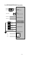
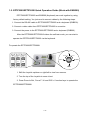
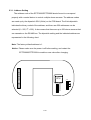
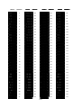
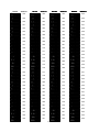
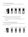
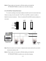
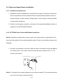
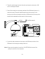
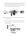
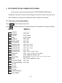
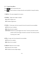
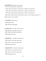
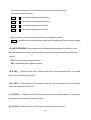
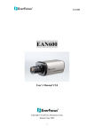
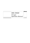
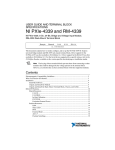
Speed Dome
EPTZ3000/EPTZ3000I
USER MANUAL
Date: Feb15, 2006
Table of Contents
1.
EPTZ3000/EPTZ3000I OVERVIEW ...................................... 1-3
1.1.
Introduction .............................................................................................1-3
1.2.
Specifications ..........................................................................................1-5
1.3.
Feature .....................................................................................................1-7
1.3.1.
Profile of EPTZ3000/EPTZ3000I ........................................................1-7
1.3.2.
EPTZ3000/EPTZ3000I Base Board ...................................................1-8
1.3.3.
EPTZ3000/EPTZ3000I Control Board ................................................1-9
1.4.
EPTZ3000/EPTZ3000I Connection .......................................................1-10
1.5.
EPTZ3000/EPTZ3000I Quick Operation Guide (Work with EKB500) .1-11
2. EPTZ3000/EPTZ3000I INSTALLATION ............................................ 2-12
2.1.
Packing List ...........................................................................................2-12
2.2.
Cable Needed.........................................................................................2-12
2.3.
Initial Setup ............................................................................................2-13
2.4.
2.5.
2.3.1.
Address Setting................................................................................2-14
2.3.2.
Communication Protocol Setting ......................................................2-17
2.3.3.
Transmission Speed Setting (Baud Rate Setting) ............................2-17
2.3.4.
RS-485 Bus Terminal Resistance.....................................................2-18
Rack and Speed Dome Installation ......................................................2-19
2.4.1.
Installation Requirements .................................................................2-19
2.4.2.
EPTZ3000 Dome Camera Wall Mount Installation ...........................2-19
2.4.3.
EPTZ3000I Dome Camera Installation.............................................2-22
Accessories ...........................................................................................2-25
2.5.1.
EPTZ-CPMA: Ceiling Pendant Mount Adapter .................................2-25
2.5.2.
EPTZ-PMA: Pole Mount Adapter......................................................2-25
1-1
2.5.3.
EPTZ- CMA: Corner Mount Adapter.................................................2-26
3. EPTZ3000/EPTZ3000I CAMERA SETUP MENU.............................. 3-27
3.1.
Structure of the Setup Menu ................................................................3-27
3.1.1.
Camera Setup Menu ........................................................................3-28
4. EPTZ3000/3000I FUNCTION SETUP AND OPERATION................. 4-34
4.1.
Manual Control Mode ............................................................................4-34
4.2.
Auto Pan Mode ......................................................................................4-34
4.3.
Position Setting .....................................................................................4-34
4.4.
Tour Mode ..............................................................................................4-35
4.5.
Alarm Link to a Position/Tour...............................................................4-36
4.6.
Other operations ...................................................................................4-36
APPENDIX : The Alarm I/O Connection................................................ 4-37
1-2
1. EPTZ3000/EPTZ3000I OVERVIEW
1.1. Introduction
EPTZ3000/EPTZ3000I, an intelligent high-speed dome camera is ready to secure
your property with its omni-directional and exact monitoring. A 30X optical and 8X
digital zoom combining with a high-performance chip makes captured images clear
and vivid. The other powerful camera functions EPTZ3000/EPTZ3000I equips with:
Wide Dynamic makes objects clear in a high illumination background.
Vertical double density interline CCD with a slower shutter and true
Day/Night function.
Electronics flip, no mechanical flip is necessary.
520 color/570 B&W TVL; PAL/NTSC image formats support.
Auto and fast focus increases the searching speed and precision.
Auto Iris adjusts the monitoring image to the best brightness.
White Balance function makes the shades of color more natural in different
light conditions.
Color / B&W images auto switching to enhance the sensitivity in a low light
condition or at night.
Private zone protects your privacy.
1-3
Furthermore, the micro control unit enables camera a nimble and exact movement
from minimal 0.01°/sec to maximal 360°/sec. It can go to every preset position in 1
second. It also has other advantages such as:
239 preset positions are available.
16 cruise tours can be set, and each tour contains up to 16 positions.
Up to 256 speed domes can be supported on a RS-485 bus when all speed
domes are controlled by keyboard EKB500.
Auto heater and fan to fit all kinds of temperature (outdoor models).
Built-in 4 alarm inputs and 1 alarm output.
All of the features make the intelligent high-speed dome camera works for a wide
range and demanding application such as banks, airports, stations, casinos, streets
of cities, intelligent buildings, and etc.
1-4
1.2. Specifications
Model
EPTZ3000 (outdoor)
EPTZ3000I (indoor)
Power Supply
AC 24V
Power consumption
70W with heater
18W without heater
Operating temperature
﹣40℃~+60℃
0℃~+40℃
Image device
1/4”, Vertical double density interline CCD
Zoom ratio
30x Optical (8x Digital zoom, max 240x)
Lens
30x optical zoom, f=3.3 mm (wide) to 99.0 mm (tele), F1.6 to F3.2
Viewing angle
H: Approx. 58.0° (wide) to 2.22° (tele end)
V: Approx. 44.8° (wide) to 1.68° (tele end)
Resolution
520 TVL : Color; 570 TVL : B/W
WDR (Wide Dynamic Range)
52dB
Minimum illumination
0.3 lux/F1.6 (50 IRE) Color; 0.05 lux/F1.6 (50 IRE) B/W
Focus
Auto/Manual
Iris Control
Auto/Manual
Shutter selection
ESC; A.FLK; Manual (1/120000~x8) selectable
Operating moisture
≤95%
Communication
RS-485
Communication speed
1200/2400/4800/9600bps
Horizontal rotation speed
0.01°/s-360°/s (1-239 grade shift gears)
Horizontal rotation range
360° unlimited rotation
Tilt rotation range
180° pendulum motion
Auto zoom speed control
Control speed auto-adjusted according to zoom length changing
Auto Pan, 2 points scanning
Can set freely
Auto Pan speed
1-239 grade available
Dwell time (2 points)
1-239 second available
Preset Positions
239 positions
Running to position speed
1-239 grade available,0.01º/s - 360º/s
Dwell time at preset position
1-60s available
Tour
16 group
Tour point per group
16 preset positions
Fan, Heater (outdoor model)
Fan and heater auto starts
Position Accuracy
±0.1°
Alarm
4 in 1 out with tour/position auto triggering
Proportional Pan Speed
Yes
Built-in menu for functions
Yes
Built-in Protocols
EVF-1, Pelco-P, Pelco-D, A-Type
1-5
Communication
RS-485
Address editable
Yes (through DIP switch)
Speed Dome Address
0-255
Manual Pan/tilt speed
Pan: 0.01º ~ 360º/s ; Tilt: 0.01º ~ 360º/s
Video Output
BNC
Safety
CE, FCC
Dimension
220(W) x 310(H)mm
Weight
3.2kg
1-6
1.3. Feature
1.3.1. Profile of EPTZ3000/EPTZ3000I
EPTZ3000
Wall Mount Bracket
M5 Bolt (Hex) x3
Base PCB board
Control board
Connection Bus
Housing
Power Cable
Inner Housing
BNC Cable
RS485 Cable
M3 Bolt x3
Mechanical Part
Bulb
Camera Module
EPTZ3000I
Power Cable
Base PCB board
BNC Cable
RS485 Cable
Control board
Housing
Clip
Connection Bus
Ceiling
Mechanical Part
Button
Camera Module
Bulb
1-7
1.3.2. EPTZ3000/EPTZ3000I Base Board
The base board that is on the bottom of the housing connects to power cable, video
cable, control cable, alarm cable, fan and heater. In order to connect to cables, the board
needs to be taken off, and put back after finishing connecting to all cables. The connectors
of cable names are marked on the board in white text. The details of the alarm connector
(JP5) are shown on the APPENDIX A.
For EPTZ3000 outdoor model, JP1, JP3 and JP6 that are two-pin connectors need to
be taken off during installing. JP1 and JP3 are connectors for heater, and they can be
switched. JP6 is a fan controller connector that turns on/off of the fan. The 3 cables are too
short to be connected to a wrong connector when putting them back.
RELAY
JP5
Video +
Video RS485 +
RS485 -
AC24
AC24
JP6
JP3
JP4
JP1
RELAY
AC24
AC24
RS485 -
RS485 +
Video -
Video +
EPTZ3000 Baseboard
JP5
EPTZ3000I Baseboard
1-8
1.3.3. EPTZ3000/EPTZ3000I Control Board
The PCB board with two dipswitches is the control board of EPTZ3000/EPTZ3000I. The
two switches are used to set address, protocol, Baud Rate, video format and terminal
resistance.
1
2
3
4
5
2
6
3
7
4
8
5
6
7
8
1-9
ON
1
ON
SW1
ID1
ID2
ID3
ID4
ID5
ID6
ID7
ID8
Protocol
SW2
BAUD
CPU
1.4. EPTZ3000/EPTZ3000I Connection
110V AC
24V AC
POWER
24V AC / 3.5 A
Adapter
BNC
1.0Vpp ± 0.2V, 75 Ω
Video Out
RS485 Tx(+)
RS485 Control Line
RS485 Tx(-)
Alarm 1
EPTZ3000/
EPTZ3000I
Alarm 2
Alarm 3
4 ALARM INPUTS
Alarm 4
GROUND
ALARM OUTPUTS
N.C.
N.O.
COM
1-10
1.5. EPTZ3000/EPTZ3000I Quick Operation Guide (Work with EKB500)
EPTZ3000/EPTZ3000I and EKB500 (Keyboard) can work together by using
factory default setting. You just need to connect cables by the following steps:
1. Connect the RS-485 cable to EPTZ3000/EPTZ3000I and a keyboard (EKB500).
2. Connect a video cable from EPTZ3000/EPTZ3000I to a monitor.
3. Connect the power to the EPTZ3000/EPTZ3000I and a keyboard (EKB500).
After the EPTZ3000/EPTZ3000I finishes the self-test mode, you can start to
operate the EPTZ3000/EPTZ3000I via the keyboard.
To operate the EPTZ3000/EPTZ3000I:
UP
IRIS
+
Focus
F.
Zoom
In
Zoom OUT
Zoom IN
LEFT
-
N.
RIGHT
Out
DOWN
1. Shift the Joystick up/down or right/left to view from camera.
2. Turn the top of the Joystick to zoom in/out.
3. Press Zoom In/Out, Focus F. /N. and IRIS +/- function keys to operate the
EPTZ3000/EPTZ3000I.
1-11
2. EPTZ3000/EPTZ3000I INSTALLATION
2.1. Packing List
There are 3 boxes that are housing, bulb and mechanical part with a camera module,
one wall mount bracket, one power adapter and one tool packet in the package. The detail
accessories list below:
Housing x1
Bulb x1
Mechanical part with a camera module x1
Wall mount bracket x1
Adapter x1
Tool packet
Glove x2
M5 Hex Allen wrench x1
Pin connector x1
M5 screw (Hex) x3 for wall mount bracket fixing
M3 screw x3 for bulb fixing
2.2. Cable Needed
Power Cable
An adapter with 24V AC/3.5A output provides the power to the EPTZ3000/EPTZ3000I.
An extension power line may be needed.
Note: The input AC voltage range of an adapter depends on different area.
Please make sure the voltage range before installing.
2-12
Video Cable
A BNC cable is used for connecting an EPTZ3000/EPTZ3000I to a DVR or a monitor.
An amplifier may be needed if the video cable is too long.
Control Cable
Basically, EPTZ3000/EPTZ3000I uses a differential pair to connect to other devices
by cascading. A cable that has low signal decline can be used as a control cable.
Alarm Cable
An alarm cable is not included in the packing list. A suitable wire that has low signal
decline can be used as an alarm cable.
2.3. Initial Setup
Initial setup includes dome address, communication protocol, transmission speed,
video format, and terminal resistance settings. All of the settings should be confirmed
before the dome is installed. The control-related setting that is address, communication
protocol and transmission speed have to be set consistently with the control device such
as a keyboard or a DVR.
Notice: Please make sure the power is off before setting, and restart the
EPTZ3000/EPTZ3000I to enable a new value after changing.
2-13
2.3.1. Address Setting
The address code of the EPTZ3000/EPTZ3000I should be set to correspond
properly with a control device to control multiple dome cameras. The address codes
are made up by the dipswitch SW1 (8 bits) on the PCB board. The 8 bits dipswitch
indicates the binary coded of the address, and there are 256 addresses can be
selected (0 ~ 255, 28 = 256). It also means that there are up to 256 dome cameras that
can cascade on the RS-485 bus. The dipswitch setting and the indicated address are
represented in the following chart.
Note: The factory default address is 1.
Notice: Please make sure the power is off before setting, and restart the
EPTZ3000/EPTZ3000I to enable a new value after changing.
1
2
3
4
5
2
6
3
7
4
8
5
6
7
8
2-14
ON
1
ON
SW1
ID1
ID2
ID3
ID4
ID5
ID6
ID7
ID8
Protocol
SW2
BAUD
CPU
Switch
ON
1
2
3
4
5
6
7
8
ON
1
2
3
4
5
6
7
8
2
3
4
5
6
7
8
ON
1
ON
1
2
3
4
5
6
7
8
ON
1
2
3
4
5
6
7
8
2
3
4
5
6
7
8
ON
1
ON
1
2
3
4
5
6
7
8
ON
1
2
3
4
5
6
7
8
2
3
4
5
6
7
8
2
3
4
5
6
7
8
ON
1
ON
1
ON
1
2
3
4
5
6
7
8
2
3
4
5
6
7
8
2
3
4
5
6
7
8
ON
1
ON
1
ON
1
2
3
4
5
6
7
8
2
3
4
5
6
7
8
2
3
4
5
6
7
8
ON
1
ON
1
ON
1
2
3
4
5
6
7
8
ON
1
2
3
4
5
6
7
8
2
3
4
5
6
7
8
ON
1
ON
1
2
3
4
5
6
7
8
ON
1
2
3
4
5
6
7
8
2
3
4
5
6
7
8
ON
1
ON
1
2
3
4
5
6
7
8
ON
1
2
3
4
5
6
7
8
2
3
4
5
6
7
8
ON
1
ON
1
2
3
4
5
6
7
8
ON
1
2
3
4
5
6
7
8
2
3
4
5
6
7
8
2
3
4
5
6
7
8
ON
1
ON
1
ON
1
2
3
4
5
6
7
8
2
3
4
5
6
7
8
2
3
4
5
6
7
8
ON
1
ON
1
Switch
Address
0
1
2
3
4
5
6
7
8
9
10
11
12
13
14
15
16
17
18
19
20
21
22
23
24
25
26
27
28
29
30
31
Address
ON
1
2
3
4
5
6
7
8
ON
1
2
3
4
5
6
7
8
2
3
4
5
6
7
8
ON
1
ON
1
2
3
4
5
6
7
8
ON
1
2
3
4
5
6
7
8
2
3
4
5
6
7
8
ON
1
ON
1
2
3
4
5
6
7
8
ON
1
2
3
4
5
6
7
8
2
3
4
5
6
7
8
2
3
4
5
6
7
8
ON
1
ON
1
ON
1
2
3
4
5
6
7
8
2
3
4
5
6
7
8
2
3
4
5
6
7
8
ON
1
ON
1
ON
1
2
3
4
5
6
7
8
2
3
4
5
6
7
8
2
3
4
5
6
7
8
ON
1
ON
1
ON
1
2
3
4
5
6
7
8
ON
1
2
3
4
5
6
7
8
2
3
4
5
6
7
8
ON
1
ON
1
2
3
4
5
6
7
8
ON
1
2
3
4
5
6
7
8
2
3
4
5
6
7
8
ON
1
ON
1
2
3
4
5
6
7
8
ON
1
2
3
4
5
6
7
8
2
3
4
5
6
7
8
ON
1
ON
1
2
3
4
5
6
7
8
ON
1
2
3
4
5
6
7
8
2
3
4
5
6
7
8
2
3
4
5
6
7
8
ON
1
ON
1
ON
1
2
3
4
5
6
7
8
2
3
4
5
6
7
8
2
3
4
5
6
7
8
ON
1
ON
1
32
33
34
35
36
37
38
39
40
41
42
43
44
45
46
47
48
49
50
51
52
53
54
55
56
57
58
59
60
61
62
63
Switch
Address
ON
1
2
3
4
5
6
7
8
ON
1
2
3
4
5
6
7
8
2
3
4
5
6
7
8
ON
1
ON
1
2
3
4
5
6
7
8
ON
1
2
3
4
5
6
7
8
2
3
4
5
6
7
8
ON
1
ON
1
2
3
4
5
6
7
8
ON
1
2
3
4
5
6
7
8
2
3
4
5
6
7
8
2
3
4
5
6
7
8
ON
1
ON
1
ON
1
2
3
4
5
6
7
8
2
3
4
5
6
7
8
2
3
4
5
6
7
8
ON
1
ON
1
ON
1
2
3
4
5
6
7
8
2
3
4
5
6
7
8
2
3
4
5
6
7
8
ON
1
ON
1
ON
1
2
3
4
5
6
7
8
ON
1
2
3
4
5
6
7
8
2
3
4
5
6
7
8
ON
1
ON
1
2
3
4
5
6
7
8
ON
1
2
3
4
5
6
7
8
2
3
4
5
6
7
8
ON
1
ON
1
2
3
4
5
6
7
8
ON
1
2
3
4
5
6
7
8
2
3
4
5
6
7
8
ON
1
ON
1
2
3
4
5
6
7
8
ON
1
2
3
4
5
6
7
8
2
3
4
5
6
7
8
2
3
4
5
6
7
8
ON
1
ON
1
ON
1
2
3
4
5
6
7
8
2
3
4
5
6
7
8
2
3
4
5
6
7
8
ON
1
ON
1
2-15
64
65
66
67
68
69
70
71
72
73
74
75
76
77
78
79
80
81
82
83
84
85
86
87
88
89
90
91
92
93
94
95
Switch
Address
ON
1
2
3
4
5
6
7
8
2
3
4
5
6
7
8
2
3
4
5
6
7
8
2
3
4
5
6
7
8
2
3
4
5
6
7
8
2
3
4
5
6
7
8
2
3
4
5
6
7
8
2
3
4
5
6
7
8
2
3
4
5
6
7
8
2
3
4
5
6
7
8
2
3
4
5
6
7
8
2
3
4
5
6
7
8
2
3
4
5
6
7
8
2
3
4
5
6
7
8
2
3
4
5
6
7
8
2
3
4
5
6
7
8
2
3
4
5
6
7
8
2
3
4
5
6
7
8
2
3
4
5
6
7
8
2
3
4
5
6
7
8
2
3
4
5
6
7
8
2
3
4
5
6
7
8
2
3
4
5
6
7
8
2
3
4
5
6
7
8
2
3
4
5
6
7
8
2
3
4
5
6
7
8
2
3
4
5
6
7
8
2
3
4
5
6
7
8
2
3
4
5
6
7
8
2
3
4
5
6
7
8
2
3
4
5
6
7
8
2
3
4
5
6
7
8
ON
1
ON
1
ON
1
ON
1
ON
1
ON
1
ON
1
ON
1
ON
1
ON
1
ON
1
ON
1
ON
1
ON
1
ON
1
ON
1
ON
1
ON
1
ON
1
ON
1
ON
1
ON
1
ON
1
ON
1
ON
1
ON
1
ON
1
ON
1
ON
1
ON
1
ON
1
96
97
98
99
100
101
102
103
104
105
106
107
108
109
110
111
112
113
114
115
116
117
118
119
120
121
122
123
124
125
126
127
Switch
1
2
3
4
5
6
7
8
2
3
4
5
6
7
8
2
3
4
5
6
7
8
ON
1
ON
1
ON
1
2
3
4
5
6
7
8
2
3
4
5
6
7
8
ON
1
ON
1
2
3
4
5
6
7
8
ON
1
2
3
4
5
6
7
8
2
3
4
5
6
7
8
ON
1
ON
1
2
3
4
5
6
7
8
2
3
4
5
6
7
8
2
3
4
5
6
7
8
ON
1
ON
1
ON
1
2
3
4
5
6
7
8
2
3
4
5
6
7
8
ON
1
ON
1
2
3
4
5
6
7
8
ON
1
2
3
4
5
6
7
8
2
3
4
5
6
7
8
ON
1
ON
1
2
3
4
5
6
7
8
ON
1
2
3
4
5
6
7
8
2
3
4
5
6
7
8
ON
1
ON
1
2
3
4
5
6
7
8
2
3
4
5
6
7
8
2
3
4
5
6
7
8
ON
1
ON
1
ON
1
2
3
4
5
6
7
8
2
3
4
5
6
7
8
ON
1
ON
1
2
3
4
5
6
7
8
ON
1
2
3
4
5
6
7
8
2
3
4
5
6
7
8
ON
1
ON
1
2
3
4
5
6
7
8
2
3
4
5
6
7
8
2
3
4
5
6
7
8
ON
1
ON
1
ON
1
2
3
4
5
6
7
8
2
3
4
5
6
7
8
ON
1
Switch
Address
ON
128
129
130
131
132
133
134
135
136
137
138
139
140
141
142
143
144
145
146
147
148
149
150
151
152
153
154
155
156
157
158
159
Address
ON
1
2
3
4
5
6
7
8
2
3
4
5
6
7
8
2
3
4
5
6
7
8
ON
1
ON
1
ON
1
2
3
4
5
6
7
8
2
3
4
5
6
7
8
ON
1
ON
1
2
3
4
5
6
7
8
ON
1
2
3
4
5
6
7
8
2
3
4
5
6
7
8
ON
1
ON
1
2
3
4
5
6
7
8
2
3
4
5
6
7
8
2
3
4
5
6
7
8
ON
1
ON
1
ON
1
2
3
4
5
6
7
8
2
3
4
5
6
7
8
ON
1
ON
1
2
3
4
5
6
7
8
ON
1
2
3
4
5
6
7
8
2
3
4
5
6
7
8
ON
1
ON
1
2
3
4
5
6
7
8
ON
1
2
3
4
5
6
7
8
2
3
4
5
6
7
8
ON
1
ON
1
2
3
4
5
6
7
8
2
3
4
5
6
7
8
2
3
4
5
6
7
8
ON
1
ON
1
ON
1
2
3
4
5
6
7
8
2
3
4
5
6
7
8
ON
1
ON
1
2
3
4
5
6
7
8
ON
1
2
3
4
5
6
7
8
2
3
4
5
6
7
8
ON
1
ON
1
2
3
4
5
6
7
8
2
3
4
5
6
7
8
2
3
4
5
6
7
8
ON
1
ON
1
ON
1
2
3
4
5
6
7
8
2
3
4
5
6
7
8
ON
1
160
161
162
163
164
165
166
167
168
169
170
171
172
173
174
175
176
177
178
179
180
181
182
183
184
185
186
187
188
189
190
191
Switch
Address
ON
1
2
3
4
5
6
7
8
2
3
4
5
6
7
8
2
3
4
5
6
7
8
ON
1
ON
1
ON
1
2
3
4
5
6
7
8
2
3
4
5
6
7
8
ON
1
ON
1
2
3
4
5
6
7
8
ON
1
2
3
4
5
6
7
8
2
3
4
5
6
7
8
ON
1
ON
1
2
3
4
5
6
7
8
2
3
4
5
6
7
8
2
3
4
5
6
7
8
ON
1
ON
1
ON
1
2
3
4
5
6
7
8
2
3
4
5
6
7
8
ON
1
ON
1
2
3
4
5
6
7
8
ON
1
2
3
4
5
6
7
8
2
3
4
5
6
7
8
ON
1
ON
1
2
3
4
5
6
7
8
ON
1
2
3
4
5
6
7
8
2
3
4
5
6
7
8
ON
1
ON
1
2
3
4
5
6
7
8
2
3
4
5
6
7
8
2
3
4
5
6
7
8
ON
1
ON
1
ON
1
2
3
4
5
6
7
8
2
3
4
5
6
7
8
ON
1
ON
1
2
3
4
5
6
7
8
ON
1
2
3
4
5
6
7
8
2
3
4
5
6
7
8
ON
1
ON
1
2
3
4
5
6
7
8
2
3
4
5
6
7
8
2
3
4
5
6
7
8
ON
1
ON
1
ON
1
2
3
4
5
6
7
8
2
3
4
5
6
7
8
ON
1
2-16
192
193
194
195
196
197
198
199
200
201
202
203
204
205
206
207
208
209
210
211
212
213
214
215
216
217
218
219
220
221
222
223
Switch
Address
ON
1
2
3
4
5
6
7
8
2
3
4
5
6
7
8
2
3
4
5
6
7
8
2
3
4
5
6
7
8
2
3
4
5
6
7
8
2
3
4
5
6
7
8
2
3
4
5
6
7
8
2
3
4
5
6
7
8
2
3
4
5
6
7
8
2
3
4
5
6
7
8
2
3
4
5
6
7
8
2
3
4
5
6
7
8
2
3
4
5
6
7
8
2
3
4
5
6
7
8
2
3
4
5
6
7
8
2
3
4
5
6
7
8
2
3
4
5
6
7
8
2
3
4
5
6
7
8
2
3
4
5
6
7
8
2
3
4
5
6
7
8
2
3
4
5
6
7
8
2
3
4
5
6
7
8
2
3
4
5
6
7
8
2
3
4
5
6
7
8
2
3
4
5
6
7
8
2
3
4
5
6
7
8
2
3
4
5
6
7
8
2
3
4
5
6
7
8
2
3
4
5
6
7
8
2
3
4
5
6
7
8
2
3
4
5
6
7
8
2
3
4
5
6
7
8
ON
1
ON
1
ON
1
ON
1
ON
1
ON
1
ON
1
ON
1
ON
1
ON
1
ON
1
ON
1
ON
1
ON
1
ON
1
ON
1
ON
1
ON
1
ON
1
ON
1
ON
1
ON
1
ON
1
ON
1
ON
1
ON
1
ON
1
ON
1
ON
1
ON
1
ON
1
224
225
226
227
228
229
230
231
232
233
234
235
236
237
238
239
240
241
242
243
244
245
246
247
248
249
250
251
252
253
254
255
2.3.2. Communication Protocol Setting
The 1st, 2nd and 3rd bits of the SW2 are used to set communication protocol. The
factory default protocol is EVF.
ON
2
3
4
4
5
5
6
6
7
7
8
8
4
4
4
3
3
3
3
2
2
2
2
Baud Rate
5
5
5
6
6
6
7
7
7
8
8
8
Terminal
Resistance
1
ON
1
ON
1
ON
1
ON
1
Protocol
PELCO-D PELCO-P A-TYPE
EVF
SW2
Notice: Please make sure the power is off before setting, and restart the
EPTZ3000/EPTZ3000I to enable a new value after changing.
Set all of protocol switches to ON; the speed EPTZ3000/EPTZ3000I will enter a
self-test mode.
2.3.3. Transmission Speed Setting (Baud Rate Setting)
The 4th and 5th bits of the SW2 on the PCB board are used to set the Baud Rate. The
default baud rate setting is 9600.
SW2
4800 BPS
2400 BPS
1200 BPS
2
2
3
3
4
4
5
5
6
6
7
7
8
8
8
8
7
8
7
6
7
6
5
6
5
4
5
4
3
4
3
2
3
2
2
Baud Rate
Terminal
Resistance
2-17
ON
1
ON
1
ON
1
ON
1
ON
1
Protocol
9600 BPS
Notice: Please make sure the power is off before setting, and restart the
EPTZ3000/EPTZ3000I to enable a new value after changing.
2.3.4. RS-485 Bus Terminal Resistance
For central controlling, the terminal resistance should be set for the device that is the
furthest one away from the controller. The 8th bit on the SW2 is a switch to enable or
disable the terminal resistance.
When it is switched ON, the BUS terminal resistance is
connected.
OFF
SW2
ON
1
ON
1
ON
1
2
2
2
3
3
3
4
4
4
5
5
5
6
6
6
7
7
7
8
8
8
Protocol
ON
Baud Rate
Terminal
Resistance
n ≦ 255
RS-485
Keyboard
DVR
Control Unit
CAM-0
CAM-1
CAM-n
Ternimal
Resistance
ON
Note: When the dome is out of control, or does not work under control well, try to switch
the terminal resistance ON.
Notice: Please make sure the power is off before setting, and restart the
EPTZ3000/EPTZ3000I to enable a new value after changing.
2-18
2.4. Rack and Speed Dome Installation
2.4.1. Installation Requirements
1. Installation should be handled by a qualified service agent and should comply with
all local regulations. Service personnel should expect potential problems such as
surface strength, surface material, falling objects, outer breaches, building vibration
or other similar conditions.
2. Check for all necessary materials, and ensure if the selected installation location is
suitable for the EPTZ3000/EPTZ3000I.
2.4.2. EPTZ3000 Dome Camera Wall Mount Installation
Notice: Installation location that is a wall, a pole or a ceiling needs to support above five
times the total weight of the camera assembly (about 16 kg) to avoid shaken images, and
dropping.
1. Set wall mount bracket on the wall. Mark the center of the holes on the wall against
the bracket holes. Use a drill to make 4 holes that can be nailed 4 0.25” X 1.25”
screws at the marks.
Notice: The length of the screws depends on the surface material. The mentioned screws
are used in the normal concrete surface.
2-19
2. Thread the cable through the hole in the wall mount bracket, and screw in 4 M8
nuts for mounting the bracket.
3. Take off the housing from the packing, and take off the PCB board (4 bolts on it.)
inside the housing. Thread the cable through the top of the housing. Fix the
housing on the wall mount bracket, and screw in 3 M5 bolts (Hex) on the top of the
bracket with the attached Hex Allen wrench to fix the housing.
M5 Bolt
Hex Allen wrench
RELAY
JP5
Video +
Video RS485 +
RS485 -
AC24
AC24
JP6
JP3
JP1
4. Connect the cable connectors to the nodes on the PCB board, and then fix the
PCB board in the housing by screwing 4 bolts on it.
Notice: Please notice the polarity of control line. The EPTZ3000 will not work if the
polarity of control line is mis-connected.
2-20
JP4
5. Align the two screw holes on the bottom of mechanical part to the two bolts on the
base of the housing, and twist the mechanical part clockwise a little bit in order to
engage it with the base. Screw the two bolts on the base, and then connect and fix
the connection bus to the PCB board on the mechanical part.
Notice: The camera module on the mechanical part is very sensitive. Please be careful
when installing this part.
6. Remove the lens protection cover before installing the bulb. Align the 3 bolt holes
into the 3 housing bolt holes, and screw three M3 bolts with the attached small
screw driver to fix the bulb.
M3 Blot
M3 Blot
GLOVE
2-21
Notice: In order to protect the bulb from dirt and scrape, please put on the gloves before
installing the bulb.
7. Turn on the power, and start to operate the EPTZ3000.
Note: When turning on the power, EPTZ3000 will enter self-inspection mode, and carry out
a self-testing program. After finishing self-inspection, you can start to operate the
EPTZ3000.
2.4.3. EPTZ3000I Dome Camera Installation
1. Take off the housing from the packing, and take off the PCB board (4 bolts on it) inside
the housing.
2. Cut the ceiling against the housing’s shape with a saw.
3. Thread the cable through the screw and the hole on the top of the housing, and tighten
up the screw to fix the cable
4. Place the housing into the hole that you just made. Fix the housing on the ceiling with
two clips, adjust the screws of clips to make the housing perfectly fit to the ceiling.
5. Connect the cable connectors to the nodes on the base board, and then fix the base
board in the housing by screwing 4 bolts on it.
2-22
RELAY
AC24
AC24
RS485 -
RS485 +
Video -
Video +
Cut the ceiling
JP5
Notice: Please notice the polarity of control line. The EPTZ3000I will not work if the
polarity of control line is mis-connected.
6. Align the two screw holes on the bottom of mechanical part to the two bolts on the
base of the housing, and twist the mechanical part clockwise a little bit in order to
engage it with the base. Screw the two bolts on the base, and then connect and fix the
connection bus to the PCB board on the mechanical part.
2-23
Notice: The camera module on the mechanical part is very sensitive. Please be
careful when installing this part.
7. Remove the lens protection cover before installing the bulb. Screw the connection
wire to the housing in order to prevent the bulb from being drop down. Align the 2
buttons on the bulb base with the 2 buttons on the housing, and push bulb base to clip
the housing.
Connection wire
Button
Button
GLOVE
Notice: In order to protect the bulb from dirt and scrape, please put on the gloves before
installing the bulb.
8. Turn on the power, and start to operate the EPTZ3000I.
2-24
2.5. Accessories
2.5.1. EPTZ-CPMA: Ceiling Pendant Mount Adapter
The pole mount is used for installing a speed dome on the ceiling indoors or outdoors.
The extension poles are available for the pole mount.
2.5.2. EPTZ-PMA: Pole Mount Adapter
The pole adapter is used for installing a wall mount bracket to a pole indoors or outdoors.
2-25
2.5.3. EPTZ- CMA: Corner Mount Adapter
The corner mount are used for installing a wall mount bracket to a 270° corner of walls
indoors or outdoors.
2-26
3. EPTZ3000/EPTZ3000I CAMERA SETUP MENU
In this section, setup and operation guide of EPTZ3000/EPTZ3000I will be
introduced. There are 18 items of the setting menu. However, there is only one line on
the line display, so using some combination keys to operate is necessary.
3.1. Structure of the Setup Menu
Press MENU to enter camera setup menu.
Press Shift + Joystick up/down to change subentries, and right/left to change the setting.
Items
CAM ID
Option
DZOOM
----------------OFF / ON
FOCUS
IRIS
AUTO / MAN
AUTO / MAN
DISPLAY
OFF / ON
OFF / ON
WBC MODE
TITLE DISP
ALM-IN1 SET
ALM-IN2 SET
ALM-IN3 SET
OFF / ON
OFF / N.C. / N.O.
OFF / N.C. / N.O.
OFF / N.C. / N.O.
ALM-IN4 SET
ALM-IN PRIO
OFF / ON
2341 / 3412 / 4123 / 1234
ALM-OUT
WDR
OFF / 3 / 5 / 10 / 20 / 30 / 60 SEC
LOW / MIDDLE / HIGH / OFF
SHUTTER
AGC
ESC / A.FLK/ 1/60 / 1/160 / 1/250 / 1/1000 / 1/2500 / 1/10000 / 1/120000 /
X2 / X4 / X6 / X8
PRIVATE ZONE
AUTO REGRESS
OFF / ON
OFF / ON
OFF / LOW / MIDDLE / HIGH
X CNT
Y CNT
PO CNT
OP HR
LOAD DEFAULT
EXIT MENU
3-27
3.1.1. Camera Setup Menu
Press MENU to enter camera setup menu.
Press Shift + Joystick up/down to change subentries, and right/left to change the setting.
1. CAM ID: The name assigned to the camera.
2. DZOOM: Digital zoom enable or disable.
ON: Enable a digital zoom.
OFF: Disable a digital zoom.
3. FOCUS: Focus type, auto focus, manual focus and one push focus are available.
AUTO: Auto focus is enabled.
MAN: Manual focus is enabled.
ONE PUSH: Enable the one push trigger focus mode. The focus lens holds the same
position until the next trigger command is received. This function prevents
the wrong focus in dark.
4. IRIS: Iris type, auto iris and manual iris are available.
AUTO: Auto iris is enabled.
MAN: Manual iris is enabled.
5. DISPLAY: Display the zoom multiple.
ON: Display the zoom multiple.
OFF: Disable the zoom multiple display.
3-28
6. WBC MODE: White balance control mode.
AUTO: Auto white balance compensation.
2000K: Manual white balance compensation in 2000K color temperature.
3200K: Manual white balance compensation in 3200K color temperature.
5100K: Manual white balance compensation in 5100K color temperature.
Note: WBC setting will affect the wide dynamic range, or other image performance. To
adjust a proper value is important.
7. TITLE DISP: Display the title.
ON: Display the title.
OFF: Disable the title display.
8. ALM-IN1 SET: The status of input alarm 1.
N.O.: Enable a normal open alarm input.
N.C.: Enable a normal close alarm input.
OFF: Disable alarm input.
9. ALM-IN2 SET: The status of input alarm 2.
N.O.: Enable a normal open alarm input.
N.C.: Enable a normal close alarm input.
OFF: Disable alarm input.
10. ALM-IN3 SET: The status of input alarm 3.
N.O.: Enable a normal open alarm input.
N.C.: Enable a normal close alarm input.
OFF: Disable alarm input.
3-29
11. ALM-IN4 SET: The status of input alarm 4.
N.O.: Enable a normal open alarm input.
N.C.: Enable a normal close alarm input.
OFF: Disable alarm input.
12. ALM-IN PRIO: The priority of alarms.
1234: The alarm priority is 1>2>3>4.
2341: The alarm priority is 2>3>4>1.
3412: The alarm priority is 3>4>1>2.
4123: The alarm priority is 4>1>2>3.
13. ALM-OUT: Duration time of the alarm output.
OFF: Disable alarm output.
3 / 5 / 10 / 20 / 30 / 60 SEC:
14. WDR :
Wide Dynamic Range.
LOW: Low wide dynamic range.
MIDDLE: Middle wide dynamic range.
HIGH: High wide dynamic range.
OFF: Disable wide dynamic range.
15. SHUTTER:
ESC: Auto electrical shutter
A.FLK: Anti-Flicker. Camera will auto adjust the shutter to reduce the flicker caused by
fluorescent light.
3-30
1/60 (NTSC) and 1/50 (PAL): default manual shutter;
1/160: 1/160 sec shutter for both NTSC and PAL
1/250: 1/250 sec shutter for both NTSC and PAL
1/1000: 1/1000 sec shutter for both NTSC and PAL
1/2500: 1/2500 sec shutter for both NTSC and PAL
1/10000: 1/10000 sec shutter for both NTSC and PAL
1/120000: 1/120000 sec shutter for both NTSC and PAL
x2: two-time default manual shutter
x4: four-time default manual shutter
x6: six-time default manual shutter
x8: eight-time default manual shutter
16. AGC: Auto Gain Control
OFF: Auto Gain Control Off
LOW: Low Auto Gain Control
MIDDLE: Middle Auto Gain Control
HIGH: High Auto Gain Control
Note: AGC setting will affect the wide dynamic range, or other image performance. To
adjust a proper value is important.
17. PRIVATE ZONE: Private zone masking.
ON: Enable the private zone masking.
OFF: Disable the private zone masking.
Press “Enter” to enter private zone setup mode, and the masking will turn into red. You
3-31
can set the masking size and position in the private zone setup mode.
In this mode, you can press
“Shift” + “6” to increase masking horizontal size;
“Shift” + “4” to decrease masking horizontal size;
“Shift” + “2” to increase masking vertical size;
“Shift” + “8” to decrease masking vertical size;
Shift Joystick to select the position where the masking is located.
“Enter” to confirm the size and position, and then the masking will turn into green again.
18. AUTO REGRESS:Auto regress to the shortest path during set a position. It can
shorten the response delay, and increase the response performance and speed dome
lifetime.
ON: Enable the auto regress function.
OFF: Disable the auto regress function.
19. X CNT: X-axis counter. This counter counts the x axis movement, and 1 is counted
when the speed dome pans 360°.
20. Y CNT: Y-axis counter. This counter counts the y axis movement, and 1 is counted
when the speed dome tilts 180°.
21. PO CNT: Position counter. This counter counts the go-position times, 1 is counted
when speed dome goes to a position once.
22. OP HR: Operation hour. This counter counts the operation hours.
3-32
23. LOAD DEFAULT: Load default setting.
Select this item, and then press “Enter” to load default setting.
Press “Clr” + “Menu” whenever you want to quit menu setting.
24. EXIT : To exit.
Select this item, and then press “Enter” to quit setting.
Press “Clr” + “Menu” whenever you want to quit menu setting.
Select this item, and then press “Enter” to quit setting.
Press “Clr” + “Menu” whenever you want to quit menu setting.
3-33
4. EPTZ3000/3000I FUNCTION SETUP AND OPERATION
4.1. Manual Control Mode
Manual control: Shift Joystick Up/Down/Left/Right, and turn it
Clockwise/Counterclockwise to control speed dome.
Use the control keys which are Zoom, Focus and IRIS function keys on the
keyboard to zoom In/Out, focus N (near)/F (Far), or IRIS +/-.
HOME Mode: The camera view will go back to the home position when there is no
keyboard operation in a specific time. The home position and the specific time can
be set by pressing Set + Home.
4.2. Auto Pan Mode
Two point auto pan: Press A.Pan to enter the auto pan mode, and then the
system will ask you to enter the auto pan speed (1~239). Press Enter to start auto
pan.
In order to set the two points, press Set + A.Pan, and then enter the dwell time
(1~239 seconds) of each point.
360° auto pan: Press Shift + A.Pan to enter the 360° auto pan. The camera will
turn 360° automatically, but not tilt.
4.3. Position Setting
Focus on a preset position: Press the number key, and then press Position to
focus on the number of preset position; or you can press Position, then enter the
preset position number, and then press Enter to focus on the number of preset
position.
4-34
Preset a position: Shift the Joystick to the position you would like to preset, and
then press Shift + Position. The system will ask you to enter the preset position
number (1~239), and then press Enter to save the position. There are up to 239
positions can be preset.
Set the parameter of a preset position: Press Set + Position to set the parameter
of a preset position. You can set the going-to speed (1~239), dwell time (1~239
seconds), and the title of the position. Shift the joystick Right/Left to change bits,
and shift the Joystick Up/Down to change the alphanumeric characteristic. The
available alphanumeric characteristics are 0~9, A~Z, &, ?, !, :, ‘, ., ,, /, -, and a
space.
Delete a preset position: Press Clr + Position to delete a preset position. The
system will ask you to enter the position number that you would like to delete, and
then press Enter.
4.4. Tour Mode
In the tour mode, you can set a tour for viewing. There are 16 tours can be set, and 16
preset positions in a tour.
One-way tour Mode: Press Tour to enter the tour mode. The system will ask you
to enter the tour number you would like to run, and starts the tour after pressing
Enter. To preset a tour before running it is necessary.
Preset a one-way tour: Press Set + Tour to preset a one-way tour. The system will
ask you to enter preset position numbers (The positions need to be preset). After
finish entering all positions, press Stop to quit, and then press Enter to save the
tour.
4-35
To-and-fro tour mode: Press Shift + Tour to run a to-and-fro tour. The system will
ask you to enter the tour number you would like to run, and starts the tour after
pressing Enter. To preset a tour before running it is necessary.
Note: The difference between the One-way tour mode and To-and-fro tour mode is that
the return modes are different. For example: There is a tour with 3 preset positions 1, 2
and 3. The camera runs 1→2→3→1→2→3 in the One-way tour mode, and 1→2→3→2→
1 in the To-and-fro tour mode.
4.5. Alarm Link to a Position/Tour
EPTZ3000/EPTZ3000I have 4 alarm inputs that can be set to link to a position or a tour
when an alarm is triggered.
Set an alarm link:
Press F1 to set an alarm link. Enter the alarm number, and then press Enter.
Switch the Joystick up/down to select a position or a tour, enter a position or tour
number, and then press Enter to confirm the alarm link setting.
Delete an alarm link:
Press Clr + F1 to delete a link of alarm to position/tour.
4.6. Other operations
The EPTZ3000/EPTZ3000I can work with a DVR that has PTZ control functions,
and a matching protocol. The available control functions depend on different DVRs.
The EPTZ3000/EPTZ3000I can work with a keyboard that has PTZ control
functions, and a matching protocol. The available control functions depend on
different keyboards.
4-36
APPENDIX : The Alarm I/O Connection
There are 4 alarm inputs and 1 alarm output available. The alarm I/O connector that is
marked as JP5 is a nine-pin connector. It is located on the PCB board of the housing.
JP5
1
~
9
RELAY
JP5
Video +
Pin #
Function
1
Alarm Input 3
2
Ground
3
Alarm Input 2
4
Alarm Input 1
5
Ground
6
Alarm Input 0
7
Normal Open (N.O.)
8
Common (COM)
9
Normal Close (N.C.)
Video RS485 +
RS485 -
AC24
AC24
JP6
JP3
JP4
JP1
4-37
EverFocus Electronics Corp.
Head Office:
China Office:
12F, No.79 Sec. 1 Shin-Tai Wu Road,
Room 609, Technology Trade Building,
Hsi-Chih, Taipei, Taiwan
Shandgdi Information Industry Base,
TEL: +886-2-26982334
Haidian District, Beijing,China
FAX: +886-2-26982380
TEL: +86-10-62971096
www.everfocus.com.tw
FAX: +86-10-62971432
www.everfocus.com.cn
USA Office:
1801 Highland Ave. Unit A
Japan Office:
Duarte, CA 91010, U.S.A.
1809 WBG MARIBU East 18F,
TEL: +1-626-844-8888
2-6 Nakase.Mihama-ku.
FAX: +1-626-844-8838
Chiba city 261-7118, Japan
www.everfocus.com
TEL : +81-43-212-8188
FAX : +81-43-297-0081
www.everfocus.com
European Office:
Albert-Einstein-Strasse 1
D-46446 Emmerich, Germany
TEL: 49-2822-9394-0
FAX: 49-2822939495
www.everfocus.de
P/N: MW01G0070B
4-38