1
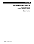
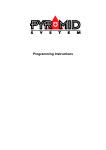
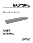
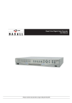
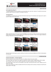
Pyramid Universal Dome Interface Installation Manual Please read this manual before operating the Pyramid system Pyramid Universal Dome Interface Installation Manual IMPORTANT The first few pages of these instructions contain important information on safety and product conformity. Please read, and ensure that you understand this information before continuing. Page 2 Installation Manual Pyramid Universal Dome Interface CONTENTS Product Safety ...................................................................................................................................................................................... 4 Electromagnetic Compatibility (EMC) ............................................................................................................................................. 4 Manufacturers Declaration of Conformance ............................................................................................................................... 4 Unpacking .............................................................................................................................................................................................. 4 Barcoding .............................................................................................................................................................................................. 4 The Universal Dome Interface ................................................................................................................................................................. 5 Connecting and Configuring the UDI ....................................................................................................................................................... 6 Connecting a Baxall Pro Dome Camera .................................................................................................................................................. 8 Connecting an Ultrak Dome Camera ....................................................................................................................................................... 8 Connecting a VCL Dome Camera ............................................................................................................................................................ 9 Connecting a Vicon Dome Camera ....................................................................................................................................................... 10 Connecting a Mark Mercer Dome Camera ............................................................................................................................................ 11 Connecting a JVC Dome Camera .......................................................................................................................................................... 11 Connecting a Pelco Dome Camera ........................................................................................................................................................ 12 Connecting a Dennard Dome Camera ................................................................................................................................................... 13 Connecting a Panasonic Dome Camera ................................................................................................................................................ 13 Connecting an AD/Sensormatic Dome Camera .................................................................................................................................... 14 Connecting a Vista Dome Camera ........................................................................................................................................................ 15 Connecting a Baxall CDR or CDH Camera ............................................................................................................................................ 15 Addressing a UDI with the Pyramid 1 Keyboard .................................................................................................................................. 16 Addressing a UDI with the Pyramid 2 Keyboard .................................................................................................................................. 16 Receiver Programming .......................................................................................................................................................................... 17 Dome Operations Available with the Pyramid 2 Keyboard ................................................................................................................... 17 Specifications ........................................................................................................................................................................................ 23 Page 3 Pyramid Universal Dome Interface Installation Manual PRODUCT SAFETY WARNING Please follow these instructions as you install the equipment and keep them for future use. Installation is only to be carried out by competent, qualified and experienced personnel in accordance with the country of installations National Wiring Regulations. Failure to do so can result in injury or death by electric shock. The module can operate from any +12V DC or 24V AC class 2 isolated power supply capable of providing 100mA. The module is susceptible to damage from Electrostatic Discharge (ESD). Take normal ESD precautions when handling your network card. ESD prevention kits are available from most electronics distributors. Do not exceed the voltage and temperature limits given in the specification. If you have any problems, contact Baxall Limited. There are no user serviceable parts in this equipment. ELECTROMAGNETIC COMPATIBILITY (EMC) CAUTION This is a Class A product. In a domestic environment this product may cause radio interference in which case the user may be required to take adequate measures. This product is intended for use in general purpose CCTV applications in a residential, commercial or light industrial EMC environment. Refer to Baxall Limited before using the product in medical and/or intrinsically safe applications or in an industrial EMC environment. The product must be installed in accordance with good installation practice for EMC to enable the product to function as intended and to prevent EMC problems. Contact Baxall Technical Support to obtain a specification defining the acceptable levels of product degradation with regard to EMC immunity. MANUFACTURERS DECLARATION OF CONFORMANCE A Declaration of Conformity in accordance with the above EU standards has been made and is on file at Baxall Limited, Stockport, SK6 2SU, England. The manufacturer declares, that the product supplied with this document is complaint with the provisions of the EMC Directive 89/336 EEC, the Low Voltage Directive LVD 73/23 EEC the CE Marking Directive 93/68 EEC and all associated amendments. UNPACKING Keep your packaging for use if your Universal Dome Interface is stored for an extended period or needs to be returned for any reason. The packaging should contain: A Universal Dome Interface (PY-UDI-L, PY-UDI-H or PY-UDI-HR) An A4 Module Description Sheet (for installation details) These instructions Two identical barcodes Check the product code on the serial number label. If you have an incorrect item or it is damaged then inform the suppliers and carriers immediately. If this is the case, do not attempt to use the equipment. BARCODING The Universal Dome Interface is supplied with two identical barcodes. Remove one and affix it to the module description sheet, remove the other and affix it to the module. The barcode gives the unique 48-bit neuron ID to the module. This neuron ID is also stored inside the module and will be transmitted onto the network whenever the service pin on the front panel of the module is pressed. Before installation, make a careful note on your module description sheet of all your installation details and the proposed location of the module. Then during subsequent installation using the Windows 95/98 installation tool the neuron ID can be entered. We recommend that during a system installation you store all module description sheets in a ring-bound file, and keep them for reference after the installation is complete. Page 4 Installation Manual Pyramid Universal Dome Interface THE UNIVERSAL DOME INTERFACE The Pyramid Universal Dome Interface (UDI) enables a range of dome products to be connected and controlled via the Pyramid network with a minimum of effort. The UDI can be configured to operate in a number of different dome protocols, and because of this it can translate commands from the Pyramid network to the correct format for the specific product. The UDI is compatible with domes manufactured by Baxall, AD/Sensormatic, Vista, Dennard, JVC, Mark Mercer, Panasonic, Pelco, Ultrak, Vicon and VCL. It is also compatible with Baxall CDR and CDH cameras. Manufacturer Models UDI Software Version Dennard 2050 Series V2.08 JVC TK-C675, TK-C676 V2.08 Mark Mercer D150, D250, D500 V2.08 Panasonic 850 Series V2.08 Pelco Spectra II and III (D-Type Protocol) V2.08 Ultrak KD6, KD6Z V1.03 or V2.08 VCL Orbiter, Jupiter V1.03 or V2.08 Vicon Surveyor V7, Surveyor 2000 V1.03 or V2.08 Baxall Pro Dome series 2.17 AD/Sensormatic SpeedDome, DeltaDome, UltraDome series 2.17 Vista/Baxall PowerDome/CDH and CDR Cameras 2.17 It is necessary to have a UDI for each individual dome camera that is added to the Pyramid network. Usually, the UDI will be located at the dome position. However, if a unidirectional transmission method is being used between the dome and UDI (i.e., a radio link), then the UDI can be located at the matrix location. The UDI is also flexible in that it can be operated from any +12V DC or 24V AC power supply capable of providing 100mA. Furthermore, the UDI is capable of receiving four alarm inputs, and these inputs can be configured as all normally-open or all normally-closed using a dip switch on the module. There are three variants of the UDI, based on the speed and type of Pyramid network they use. Other than this, there are no external or operating differences between the three variants. The PY-UDI-L runs on a low speed (9.8k b.p.s.) RS485 network while the PY-UDI-HR runs on a high speed (78k b.p.s.) RS485 network. The third variant, PY-UDI-H, runs on a high speed (78k b.p.s.) FTT10 network. The figure below shows a typical system layout when a UDI is connected: +12 V DC or 24V AC Power Supply Dome Camera Telemetry (i.e., RS485) Pyramid Module (e.g. Pyramid 2 Keyboard) Rx Tx 9 11 13 15 2 4 6 8 10 12 14 16 17 19 21 23 25 27 29 31 18 20 22 24 26 28 30 32 1 2 3 4 SERIAL 1 SERIAL 2 SERIAL 3 SERIAL 4 5 SERIAL 5 SERIAL 6 SERIAL 7 33 35 37 39 41 43 45 47 34 36 38 40 42 44 46 48 SERIAL 8 - P OWER 9 - 15V 7 DOME DATA 2 3 4 ALARM I/P C OFF Tx 1 2 34 +BIAS T NO NC +- + - PYRAMID DATA (i.e., RS485, FTT10) NETWORK ON 5 +- Rx 1 Pyramid Telemetry 3 SERVICE UDI Connection Panels Up to 4 Alarm Inputs 1 DOME SELECTION + 12V DC 24V AC Dome Camera Video Connection between Dome Camera and Pyramid Matrix (to enable image viewing) 6 7 8 9 10 11 12 13 14 15 16 48M16 SYNC PRINTER M/S INTERFACE Pyramid Matrix Typical UDI Layout Page 5 Pyramid Universal Dome Interface Installation Manual CONNECTING AND CONFIGURING THE UDI The two end panels of the Universal Dome Interface contain all the connectors and switches that are required to connect and configure the device. The panels also contain a number of receive and transmit LEDs which enable easy system diagnosis, and a service pin that is used when the UDI is addressed. 2 1 4 5 Tx 3 Rx 12V DC 24V AC DOME SELECTION SERVICE DOME DATA Dome Data End Panel of the UDI 8 7 6 9 Rx 1 2 3 4 ALARM I/P C OFF Tx 1 2 3 4 +BIAS T NO NC PYRAMID DATA Pyramid Data End Panel of the UDI Power Connection - Connect the power supply to this 2-pin removable terminal block. This can be any +12V DC or 24V AC power supply capable of providing 100mA. The connection is polarity insensitive. Dome Selection Dip Switches - It is necessary to set these dip switches so that the UDI knows which dome camera product is to be connected. The UDI is compatible with domes manufactured by Baxall, AD/Sensormatic, Dennard, JVC, Mark Mercer, Panasonic, Pelco, Ultrak, Vicon, Vista and VCL. Baxall CDR and CDH cameras are also supported. Consult the table below in order to set the dome selection dip switches for the product in use. The UDI will need to be powered off, then powered on again if a different protocol is selected. Page 6 Installation Manual Pyramid Universal Dome Interface CONNECTING AND CONFIGURING THE UDI Dip switch number 6 is used to enable or disable the auto-iris function. If the auto-iris functionality is enabled (dip switch 6 UP), the iris level on the connected device will be readjusted for the lighting conditions every thirty seconds. If this functionality is disabled (dip switch 6 DOWN), iris adjustments will have to be made manually using a system keyboard. Service Pin - The service pin is used to address the UDI. When the service pin is pressed (use a small screwdriver to do this), the service pin LED will light and a unique identifier known as a neuron ID is transmitted to all other devices that are connected to the UDI. The purpose of this is to establish communication between the UDI and the other devices in the Pyramid network. Dome Data LEDs - The LED labelled Rx lights to indicate when data is being sent from the dome camera to the UDI. The LED labelled Tx lights to indicate when data is being sent from the UDI to the dome camera. This allows for easy system diagnosis. Dome Data Connector - This three-way terminal block is used to connect the UDI to the dome camera. At the UDI end, the connections are common. The dome camera is connected to the UDI using pins 2 and 3 (labelled - and +) and a ground connection should be made on pin 1. The connections at the dome camera end are dependent on the type of dome camera in use. See the relevant section for more details about the connections that need to be made at the dome camera. Alarm Input Connector - Up to four alarm inputs can be connected to the UDI using this terminal. Connect each alarm input to one of the four numbered pins, and make a common connection for each input to the pin labelled with a C (common). When alarm inputs are connected to the UDI, they will use the address that is assigned to the UDI itself. For example, if the UDI is assigned camera address 21, the alarm inputs will be assigned to alarm input unit 21. Once the unit has been addressed and connected to the Pyramid network, the alarm inputs can be configured in the same way as a Pyramid Alarm Input Module. This would be done using the Pyramid Matrix menu systemfor more details, see the Pyramid Matrix Programming Manual. A UDI addressed between 127 to 144 will use the alarm input box references 1 to 18 respectively (see table below). For example, an alarm input from UDI 143 holds an alarm box input address of 17. UDI address numbers 1 2 ... 126 127 128 ... 144 Alarm box address numbers 1 2 ... 126 1 2 ... 18 The state of the alarm inputs (i.e., all normally-open or all normally-closed) can also be configured using dip switch 4 on the four-way switch bank . If the switch is in the OFF position (down) then all the alarm inputs are normally-closed. If the switch is in the ON position (up), then all the alarm inputs are normally-open. Pyramid Data LEDs - The LED labelled Tx lights to indicate when data is being sent from the UDI to the Pyramid network. The LED labelled Rx lights to indicate when communication is taking place on the Pyramid network (not just to the UDI). This allows for easy system diagnosis. Biasing Switches - Pyramid networks should be biased and terminated. Typically, biasing is applied to the first module of a network and termination is applied to the first and last modules. All other modules should be unbiased and unterminated. If it is necessary to apply biasing to the UDI, move both dip switch 1 and 2 into the UP position. To apply termination to the UDI, move dip switch 3 into the UP position. Dip switch 4 is used to set the state (i.e., all normally-open or all normally-closed) of any alarm inputs that are for more details. connected to the UDI. See Alarm Input Connector Note For connections to BT, Teleste and AMG fibre optic equipment, no biasing should be applied. Page 7 Pyramid Universal Dome Interface Installation Manual CONNECTING AND CONFIGURING THE UDI Pyramid Data Connector - This three-way terminal is used to connect the UDI to the Pyramid network. This can be either a RS485 or FTT10 network depending on the UDI variant in use. Connect the UDI to the network using pins 2 and 3 (labelled + and - to indicate polarity), and connect the cable screen to ground on pin 1 (labelled ). A good connection to the local ground plane is also required, and this should also be made to the Pyramid Data Connector on pin 1 (labelled ). This is necessary to ensure compliance with ESD directives and to protect against transients on any connections. CONNECTING A BAXALL PRO DOME CAMERA To connect a Baxall Pro Dome camera to the UDI, follow the steps below: CAUTION When connecting the UDI to a dome, reference should also be made to documentation provided with the dome. 1. Remove the dome assembly from the base. Connect the wire from the from the UDIs Dome Data Connector to the nine-pin connector on the underside of the dome assembly: Connecting and configuring a Baxall Pro Dome 2. Use the three rotary switches, labelled 1, 10 and 100, to set the dome address to 1. To do this, set rotary switch 1 to 1, and rotary switches 10 and 100 to 0, as shown in the diagram above. 3. Reconnect the dome assembly to the base. CONNECTING AN ULTRAK DOME CAMERA To connect an Ultrak dome camera to the UDI, follow the steps below: CAUTION When connecting the UDI to a dome, reference should also be made to documentation provided with the dome. 1. Remove the dome camera from its housing. 2. On the base inside the housing, connect the eight-way terminal block labelled TB1 to the wire from the UDIs Dome Data Connector. Use the diagram below as a guide: WIRES FROM DOME DATA CONNECTOR ON UDI: + 24V 24V RX - RX + TX + TX - TB1 +- FROM GROUND TERMINAL FROM + TERMINAL FROM - TERMINAL Connecting an Ultrak Dome to the UDI Page 8 Installation Manual Pyramid Universal Dome Interface CONNECTING AN ULTRAK DOME CAMERA 3. On the dome camera itself there is a PCB which includes three rotary switches. These rotary switches are labelled S1, S2 and S3, and they should be used to set the dome address to 1. To do this, set the first rotary switch (S3) to 0, the second rotary switch (S2) to 0 and the third rotary switch (S1) to 1, as shown below: White indicates switch position S4 S3 S2 S1 Configuring an Ultrak Dome 4. Next to the three rotary switches, there are four dip switches (S4) which are used to set the dome protocol. The dome protocol should be set to Maxpro. To do this for Ultrak firmware versions J and later, push the first switch DOWN and leave the remaining three switches UP, as shown in the diagram above. 5. Refit the dome camera into the housing. CONNECTING A VCL DOME CAMERA To connect a VCL dome camera to the UDI, follow the steps below: CAUTION When connecting the UDI to a dome, reference should also be made to documentation provided with the dome. 1. Unscrew the lid of the weatherproof box which contains the power supply unit for the dome camera. 2. Connect the six-way terminal block labelled CON3 to the wire from the UDIs Dome Data Connector. Use the diagram below as a guide: WIRES FROM DOME DATA CONNECTOR ON UDI: DATA + DATA - 24V AC 24V AC VIDEO GND FROM GROUND TERMINAL FROM - TERMINAL FROM + TERMINAL CON3 Connecting a VCL Dome to the UDI 3. Fix the lid back in place. 4. Remove the weatherproof screen from the dome camera itself to reveal the camera PCB. 5. Using the block of eight dip switches labelled ADDRESS, set the dome address to 1. To do this, move the switch labelled 1 to the ON position and ensure the other seven switches are set to the OFF position, as shown below: White indicates switch position ADDRESS Configuring a VCL Dome 6. Refit the weatherproof screen to the dome camera. Page 9 Pyramid Universal Dome Interface Installation Manual CONNECTING A VICON DOME CAMERA To connect a Vicon dome camera to the UDI, follow the steps below: CAUTION When connecting the UDI to a dome, reference should also be made to documentation provided with the dome. 1. Connect the five-way terminal block on the top of the Vicon dome camera to the wire from the UDIs Dome Data Connector. Use the diagram below as a guide: Connecting a Vicon Dome to the UDI 2. On the top of the Vicon dome camera, locate the two blocks of dip switches labelled S1 and S2. ON NTSC VICOAX SIMPLEX RS485 3. On the block of dip switches labelled S2, turn the RS485 and Simplex switches to the ON position as shown below: S2 S1 1 2 4 8 16 32 64 128 OFF PAL VPS DUPLEX RS422 White indicates switch position UNIT ADDRESS Configuring a Vicon Dome 4. Using the block of dip switches labelled S1, set the dome address to 1. To do this, move the switch labelled 1 to the ON position and ensure the other seven switches are set to the OFF position. Use the diagram above as a guide. Note To use Vicon dome cameras with the UDI, the baud rate of the dome should be set to 4800 baud. This is done automatically on most Vicon models, including the Surveyor 2000 which has an auto-detect baud rate feature. Page 10 Installation Manual Pyramid Universal Dome Interface CONNECTING A MARK MERCER DOME CAMERA To connect a Mark Mercer dome camera to the UDI, follow the steps below: CAUTION When connecting the UDI to a dome, reference should also be made to documentation provided with the dome. 1. Remove the top panel from the dome camera housing. The connections are made inside this top panel. 2. Inside the top panel, locate the twelve-way terminal block to which power, video, alarm and network connections are made. Connect the wire from the UDIs Dome Data Connector to the terminals marked RS485A and RS485B as shown below: WIRES FROM DOME DATA CONNECTOR ON UDI: SPARE ALARM 2 ALARM 1 SPARE RS485 B RS485 A + RS422 - RS422 VIDEO GROUND - 24V AC + 24V AC FROM GROUND TERMINAL FROM - TERMINAL FROM + TERMINAL Connecting a Mark Mercer Dome to the UDI 3. Inside the top panel, there are three rotary switches. These rotary switches are labelled S1, S2 and S3, and they should be used to set the dome address to 1. To do this, set the first rotary switch (S3) to 0, the second rotary switch (S2) to 0 and the third rotary switch (S1) to 1 as shown below: S1 S2 S3 Configuring an Mark Mercer Dome 4. Refit the top panel to the dome camera housing. CONNECTING A JVC DOME CAMERA To connect a JVC dome camera to the UDI, follow the steps below: CAUTION When connecting the UDI to a dome, reference should also be made to documentation provided with the dome. 1. Locate the data connector on the top of the dome. The connector is slightly different for TK-C675 and TK-C676 models as shown below. 2. Connect the wire from the UDIs Dome Data Connector to the terminals marked Rx+ and Rx- as shown in the diagram below. There is no need to connect the terminals marked Tx+ and Tx- as the dome is to operate in simplex mode. RX- RX+ TX+ FROM + TERMINAL FROM - TERMINAL TX- TK-C676 MODEL TK-C675 MODEL FROM - TERMINAL FROM + TERMINAL WIRES FROM DOME DATA CONNECTOR ON UDI Connecting a JVC Dome to the UDI Page 11 Pyramid Universal Dome Interface Installation Manual CONNECTING A JVC DOME CAMERA 3. Locate the rotary address switches and the settings dip switch panel on the dome camera. On the TK-C675, they are located on the side of the dome camera, while on the TK-C676, they are located on the underside of the top panel. 4. Using the two rotary switches, set the dome address to 1. To do this, set the right rotary switch to 1, and the left rotary switch to 0 as shown in the diagram below: Configuring an JVC Dome 5. Using switch 4 and 5 on the dip switch panel, set the dome camera to Multidrop Simplex mode. To do this, switch 4 should be set to the ON position and switch 5 should also be set to the ON position. CONNECTING A PELCO DOME CAMERA To connect a Pelco dome camera (Spectra II model) to the UDI, follow the steps below: CAUTION When connecting the UDI to a dome, reference should also be made to documentation provided with the dome. 1. Remove the lower dome and dome drive by aligning and pushing in the coloured tabs. The back box is now accessible. 2. Open the hinged door to the back box, by pushing the tab lock towards the wall of the unit. The dome PCB will be visible inside. 3. On the PCB, connect the four-way terminal block to the wire from the UDIs Dome Data Connector. Use the diagram below as a guide: WIRES FROM DOME DATA CONNECTOR ON UDI: RX - FROM - TERMINAL RX + FROM + TERMINAL TX TX + Connecting a Pelco Dome to the UDI 4. On the top of the dome drive, locate the two blocks of dip switches labelled SW1 and SW2. 5. Using the block of dip switches labelled SW1, set the dome to operate in D-type protocol at 2400 baud. To do this, move the switch labelled 2 into the ON position and ensure that the other switches are set to the OFF position, as shown below. White indicates switch position Configuring a Pelco Dome 6. Using the block of dip switches labelled SW2, set the dome address to 1. To do this, move the switch labelled 1 into the ON position and ensure that the other switches are set to OFF, as shown in the diagram above. 7. Reassemble the dome camera. Note The location and numbering of the dip switches may differ between Pelco Spectra II and Spectra III dome cameras. However, the settings that should be used are consistent from product to product. Consult the Pelco documentation for more details. Page 12 Installation Manual Pyramid Universal Dome Interface CONNECTING A DENNARD DOME CAMERA Dennard dome cameras are supplied with a flying lead connector which is connected to the socket on the top of the dome housing. The flying lead connector is a multicore cable, and two of the wires are used specifically for network connections. To connect these wires to the UDI, follow the steps below: CAUTION When connecting the UDI to a dome, reference should also be made to documentation provided with the dome. 1. Connect the yellow and green wires on the multicore cable to the UDIs Dome Data Connector. The green wire should be connected to the - terminal and the yellow wire to the + terminal as shown below: DOME DATA DENNARD DOME MULTICORE CABLE YELLOW WIRE GREEN WIRE Connecting a Dennard Dome to the UDI 2. To address the dome camera it is necessary to remove the protective parts of the dome. First, carefully remove the retaining screws and lift away the outer hemisphere. 3. Locate the two fixing screws and remove the inner shroud. The dome address switches should now be clearly visible on the lower PCB. 4. Using the switches, set the dome address to 1. To do this, set both the blue switch and the yellow switch to the 0 position. 5. Refit the inner shroud and outer hemisphere, taking care to tighten the fixing screws. CONNECTING A PANASONIC DOME CAMERA Panasonic dome cameras are fitted with a multiple connector lead. There are five connectors on the lead, and each connector is used for a different purpose (i.e., alarms, power, video, data). The wires from the UDIs Dome Data Connector are connected to the dome using the data connector of this lead. To make this connection, follow the steps below: CAUTION When connecting the UDI to a dome, reference should also be made to documentation provided with the dome. 1. Wire a female data connector with the wires from the UDIs Dome Data Connector as shown below. The pre-wired male connector from the dome can then be inserted into the female connector to provide the data path between dome and UDI. PRE-WIRED PANASONIC DATA CONNECTOR DATA TRANSMISSION DATA RECEPTION FEMALE CONNECTOR BROWN GND RED T (B) ORANGE T (A) WIRES FROM DOME DATA CONNECTOR ON UDI: YELLOW R (B) FROM + TERMINAL GREEN R (A) FROM - TERMINAL Connecting a Panasonic Dome to the UDI 2. On the top of the dome camera, there is a block of eight dip switches labelled SW1. Use these switches to set the dome address to 1. To do this, move the switch labelled 8 into the ON position and ensure that the other switches are set to OFF. Page 13 Pyramid Universal Dome Interface Installation Manual CONNECTING AN AD/SENSORMATIC DOME CAMERA To connect a Sensormatic dome camera to the UDI, follow the steps below: CAUTION When connecting the UDI to a dome, reference should also be made to documentation provided with the dome. 1. Remove the dome assembly from the base. The dome can be connected to the UDI in one of two ways. Connect the wires to either the I/O board fitted inside the base cover as shown in A - Connecting a Sensormatic dome to the UDI, or the nine pin connector located on the underside of the dome assembly as shown in B - Connecting and Configuring a Sensormatic dome. A - Connecting a Sensormatic dome to the UDI B - Connecting and configuring a Sensormatic dome 2. The three rotary switches labelled 1, 10 and 100, are used to set the dome address to 1. To do this, set rotary switch 1 to 1, and rotary switches 10 and 100 to 0, as shown in B - Connecting and Configuring a Sensormatic dome. 3. Reconnect the dome assembly to the base. Page 14 Installation Manual Pyramid Universal Dome Interface CONNECTING A VISTA DOME CAMERA To connect a Vista dome camera to the UDI, follow the steps below: CAUTION When connecting the UDI to a dome, reference should also be made to documentation provided with the dome. 1. Remove the dome from the mounting bracket to expose the connectors. 2. Connect the wire from the UDIs Dome Data Connector, using the diagram below as a guide: Connecting a Vista PowerDome to the UDI 3. Refit the dome camera to the mounting bracket. 4. The dip switches on the camera can be accessed without removing the camera from the casing. Set dip switch number 1 to ON and all others to OFF, as shown below: 12 1 ON Configuring an Vista PowerDome CONNECTING A BAXALL CDR OR CDH CAMERA To connect a Baxall CDR or CDH camera to the UDI, follow the steps below: CAUTION When connecting the UDI to a CDR or CDH camera, reference should also be made to documentation provided with the camera. 1. Connect the D-type Comms I/O Connector on the rear of the camera to the wire from the UDIs Dome Data Connector. Use the diagram below to connect to pins 1, 2 and 5 of the Comms I/O Connector: Connecting a CDH or CDR Camera to the UDI 2. Referring to the relevant camera manual, use the camera menu system to set the communication protocol to Baxall, the baud rate to 9600 and the camera address to 00001. Page 15 Pyramid Universal Dome Interface Installation Manual ADDRESSING A UDI WITH THE PYRAMID 1 KEYBOARD A UDI can also be addressed using the Pyramid 1 Keyboard. Follow the steps below: 1. Connect up a Pyramid Mk1 Keyboard to the UDI. This can be done directly by connecting the network card on the keyboard to the Pyramid Data Connection on the UDI, or remotely through the Pyramid network in the normal way. 2. Using the keyboard, insert the Installers Card and log on with the PIN number 1892. 3. Press the key sequence 100 and then the Function key. The left hand side of the keyboard display will show Fn 0100 to indicate that self binding mode has been invoked. 4. Repeatedly press the List Down key, until the LCD display shows the option Replace RX. 5. Once this option is displayed, select soft key number 1 marked Yes. At this point, the keyboard is now waiting for the UDI to identify itself using the service PIN. 6. Press the service pin on the UDI. The UDIs neuron ID is transmitted onto the network and the keyboard display will show the text Receiver Identified. 7. Type in the node ID you require this UDI to be configured to, and then press the Camera Select key. After a short delay, the keyboard will then display the message Subnet Node Calculated. 8. After 10 seconds, the keyboard will then log itself out automatically. Troubleshooting Q I pressed the service PIN on the UDI, but the keyboard did not show the Receiver Identified message. A No data is coming through, check the data cabling between the UDI and the keyboard. Q I got to stage 7, but the Subnet Node Calculated message remained on the keyboard screen and the keyboard did not log off. A Data is only being transmitted in one direction. Check to see if the data cable has been connected to the correct side of the communications card, or if one side of the twisted pair has become disconnected. Note The UDI can also be addressed and installed using the Pyramid Installation Tool. This software allows remote configuration of the Pyramid system using a PC. See the Pyramid Installation Tool Operating Manual for more details. ADDRESSING A UDI WITH THE PYRAMID 2 KEYBOARD Each UDI that is connected to the Pyramid system must be assigned a unique address called a node ID, and an operator with installer privileges can do this using the Pyramid 2 Keyboard. Configuration of the UDI requires its service button to be pressed (located on the Dome Data end panel of the module), and this may be a two man operation if the UDI is located remotely from the keyboard. For this reason, it is easier to address a UDI before it is added to the network, and this can be done using a special mode of the Pyramid keyboard called Self-Bind (also known as Fn 100). Self-binding mode is commonly used when configuring telemetry receivers, or when cameras need to be controlled in a system without a CCTV matrix. During the self-binding process, the installer can set up the network address, which includes the node IDthe number that is entered on a keyboard to indicate which device is to be controlled (e.g., Camera receiver number 4). Once the network address has been configured, the UDI and its associated dome camera can be attached to the network and controlled through the Pyramid matrix. To address a UDI in self-binding mode, follow the steps below: 1. Connect up a Pyramid 2 Keyboard to the UDI. This can be done directly by connecting the network card on the keyboard to the Pyramid Data Connection on the UDI, or remotely through the Pyramid network in the normal way. 2. Log onto the Pyramid 2 Keyboard using the installer password. The Installer Logon screen is displayed, where you can log on with the PIN number 1892. 3. Press the Function 100 soft-key. The Direct Access screen is displayed. 4. Press the Receiver soft-key. 5. Press the Rx Utilities screen key. 6. Press the Unit Address Type soft-key. The Addressing screen is displayed. Page 16 Installation Manual Pyramid Universal Dome Interface ADDRESSING A UDI WITH THE PYRAMID 2 KEYBOARD 7. Press the Receiver Address soft-key. The keyboard LCD displays a message asking the operator to press the service pin. 7 12... 12... 6 Operator Rx Utilities Operator Rx Utilities 5 Addressing a UDI 8. So that the keyboard can identify the UDI, press its service pin. On the UDI, the service pin is a small button inside an access hole. Use a small screwdriver to press the service pin. When the service pin is pressed, the UDIs neuron ID is transmitted to all other devices on the Pyramid network, or in the case of self-bind mode, to the keyboard. The neuron ID is a unique identifier which is used to establish communication between the UDI and all other devices. Once the UDI has been identified by the keyboard, it can be assigned a node ID. 9. The keyboard LCD displays a message asking the operator to enter the new node ID. The node ID is the visible part of a network address, as it is the number that an operator enters on a keyboard to indicate the device that is to be controlled (e.g., Camera receiver number 3). Use the number keys to enter the node ID. 10. Press the Receiver Address soft-key again to confirm the node ID. The keyboard LCD displays a message confirming the address. RECEIVER PROGRAMMING In the same way that it is used to program Pyramid AC and DC receivers, the Pyramid 2 Keyboard can be used to carry out more advanced UDI programming (e.g., presets, preset patrols, random patrols). For more details on how to do this, see the Pyramid 2 Keyboard Operating Manual. A copy of the manual is supplied with the Pyramid 2 Keyboard, and can also obtained from the Baxall website at www.baxall.com, or from Baxall Technical Support. UDI programming can also be achieved using the Pyramid 1 Keyboard. Instructions on how to do this can be obtained from Baxall. Note The number of presets that can be programmed to the UDI are limited by the storage capacity of the dome products in use. DOME OPERATIONS AVAILABLE WITH THE PYRAMID 2 KEYBOARD Once a dome has been connected to the Pyramid system using a UDI, a Pyramid 2 Keyboard in that network can control the core functions of the dome. The dome is selected in the same way as an AC or DC receiverselect a monitor, enter the camera address and then press the key. Images from the dome camera will be displayed on the selected monitor, and the standard keyboard PTZ operations will be available. These core functions (e.g., pan, tilt, zoom, focus) are transparent from product to product. A number of special operations (e.g. vector scans, learnt tours, colour/mono flip) may also be available depending on the type of dome in use. Use the commands detailed in The Dome PTZ Quick Reference Table to access these. If a dome camera has a built-in menu system, it can be accessed through the UDI. To do this, use the 128 Preset function to put the UDI into Menu mode. However, if an operator enters the menu system using this function and later exits it without first taking the UDI out of Menu mode, PTZ operation will be disabled. To enable PTZ operation once more, it is necessary to exit Menu modethis is achieved by invoking the 128 Preset function again. Read the following dome-specific sections, referring to the tables at the back of this manual. Read these instructions in conjunction with the manual supplied with the dome product itself. The procedure for programming presets can be found in the Pyramid 2 Keyboard Operating Manual. Page 17 Pyramid Universal Dome Interface Installation Manual DOME OPERATIONS AVAILABLE WITH THE PYRAMID 2 KEYBOARD Baxall ProDome The UDI enables the user to use the dome cameras menu system (when installed). To enter the dome camera menu system use the keyboard to: 1. Select a monitor on which to view the menus by pressing the monitor number (soft-keys 1 to 9) followed by the monitor soft-key. 2. Select a dome camera by pressing the camera number (soft-keys 1 to 9) followed by the camera soft-key. 3. Recall preset 128 to enter the menu system. To navigate the dome camera menu system: Use joystick up/down movements to choose menu items and menu parameters. Use joystick left/right movements to move cursor left/right one character. Use joystick clockwise/counterclockwise movements, or the Zoom IN / Zoom OUT key to change selected parameters. Press the Focus FAR / Focus NEAR key to select menu items or parameters. 4. Once amendments are complete, exit the menu system by selecting: Quit Without Saving - this will exit the dome menu without saving any changes. Exit and Save Changes - this will save any changes and exit the dome menu. Ultrak The on-screen menu system can be accessed by entering 128 Preset on the keyboard. Numeric entries can then be used to select each line of a menu or sub-menu. For example, to select line 1 in a menu, press the number 1 key followed by the Preset soft-key. Whilst in the menu system it should be noted that: Numeric entries are enabled using presets 1-10 (10 being 0). Zoom In (twist joystick clockwise) is used as the Enter function. Zoom Out (twist joystick anti-clockwise) is used as the Escape function. The Aux 1 soft-key is used to toggle between Menu and PTZ mode. This is useful in the Preshot menu (accessed using Preset 126) where it is necessary to enter PTZ mode without exiting the menus. In the Vector Scan menu (accessed using Preset 125), the joystick can be used to move between entries in the table. To leave the menu system, return to the Main menu using the Zoom Out function and from here, use 128 Preset to exit the menus on the dome and on the UDI. If the menu system is exited incorrectly, the pan, tilt and zoom functions may not be available. If this is the case, simply enter 128 preset and control will be made available. Dennard, JVC, Panasonic The menu systems on Dennard, JVC and Panasonic dome cameras are operated using similar keyboard functions: Use the Preset 128 function to enter and exit Menu mode. The Aux 1 soft-key is used to toggle between Menu and PTZ mode. Move the joystick up and down to navigate up and down menus and move it left and right to change menu values. Zoom In (twist joystick clockwise) is used as the Enter function (i.e. to select menu items and to confirm values). Zoom Out (twist joystick anti-clockwise) is used as the Escape function on JVC cameras, while the Iris Open key is used as the Escape function on Panasonic cameras. Page 18 Installation Manual Pyramid Universal Dome Interface DOME OPERATIONS AVAILABLE WITH THE PYRAMID 2 KEYBOARD When in Menu mode on a Panasonic dome camera, it is possible to enter the Special menu by pressing the Iris Close key. After programming a preset on a Dennard Dome camera, press the Iris Open key to re-enable PTZ fuctionality. On a JVC Dome camera, if the menu is exited by using the joystick, PTZ functionality will freeze. To overcome this, re-enter the menu system by twisting the joystick anti-clockwise. Exit the menu system correctly by invoking Preset 128. When entering text characters on a JVC Dome camera, ensure that Aux 1 is active (on) and twist the joystick clockwise to enter characters. Vicon The Pyramid 2 Keyboard can be used to operate a Vicon dome camera menu system as follows: Use the Preset 128 function to enter and exit Menu mode. The Aux 1 soft-key is used to toggle between Menu and PTZ mode. Move the joystick up and down to navigate up and down menus, and move it left and right to change menu values. Zoom In (twist joystick clockwise) is used as the Enter function (i.e. to select menu items and to confirm values). The Focus Near key is used as the Escape function. Pelco The Pyramid 2 Keyboard can be used to operate a Pelco dome camera menu system as follows: Use the Preset 128 function to enter and exit Menu mode. The Aux 1 soft-key is used to toggle between Menu and PTZ mode. Move the joystick up and down to navigate up and down menus and also to select menu values. The Iris Open key is used as the Enter function (i.e. to select menu items and to confirm values). Sensormatic UltraDome II, III, IV, V, VI and AD DeltaDome II and III The Pyramid 2 Keyboard can be used to operate a Sensormatic/AD dome camera menu system as follows: Recall Preset 128 to enter the domes menu system. The Focus Near key is used to make selections. Move the joystick to navigate the menu system and selection lists. Use the Zoom collar of the joystick to cycle entries in the selected field. VCL, Mark Mercer VCL and Mark Mercer dome cameras do not have a menu system. Vista PowerDome The Pyramid 2 Keyboard can be used to operate the menu system of a Vista PowerDome as follows: Recall preset 128 to enter the menu system. Enter the code 1 [preset], 2 [preset], 3 [preset], 4 [preset]. The joystick is used to navigate the menu system and selection grids. Twist the zoom collar of the joystick clockwise to enter selections. Twist the zoom collar of the joystick anti-clockwise to escape. Enter Preset 128 to re-enable the joystick. Baxall CDR and CDH Cameras The Pyramid 2 Keyboard can be used to operate the menu system on a Baxall CDR or CDH camera as follows: Recall preset 128 to enter the menu system. Move the joystick up and down to navigate up and down menus, and move it left and right to change menu values. Zoom In (twist joystick clockwise) is used as the Enter function (i.e. to select menu items and to confirm values). Page 19 Page 20 See note See note Toggle Colour/IR mode 123 Access/Exit Main Menu Access/Exit Main Menu O Dome PTZ Operation Quick-Reference Table Access/Exit Main Menu 180 Flip Digital Zoom On/Off Access Menu 3 Access Menu 2 Auto U-Turn On/Off Access Menu 4 O 180 Flip Access/Exit Main Menu Program Tour Start/Stop O 180 Flip Program Pattern Note: See Dome vendor’s specification for preset availability (maximum 100 presets). Some dome variants may not support all features listed. 180O Flip Access/Exit Main Menu Enter dome menu system 128 AUX 4 Program Learnt Tour 1 Program Pattern 3, Save 127 Colour/Mono Flip Access Preshot Menu Program Pattern 2, Save Colour/Mono Flip AUX 3 Access Vector Scan Menu Program Pattern 1, Save 126 Access Sector Menu Colour/Mono Flip 125 124 Engage auto-focus, auto-iris 122 O Enter dome menu system Program Pattern 3, Save Program Pattern 2, Save Program Pattern 1, Save Toggle Colour/IR mode Engage auto-focus, auto-iris O 180 Flip Recall Learnt Tour 3 180 Flip 121 180 Flip Recall Learnt Tour 3 120 O Recall Learnt Tour 3 Auto Tour 2 Recall Learnt Tour 2 119 180 Flip Recall Learnt Tour 2 Auto Tour 1 Recall Learnt Tour 1 118 180O Flip Recall One-Pass Patrol 2 Recall Vector Scan 7 117 O Recall Learnt Tour 2 Recall One-Pass Patrol 1 Recall Vector Scan 6 116 180O Flip Colour/IR mode Enter Menu system Program Learnt Tour 1 Colour/IR mode O 180 Flip Recall Learnt Tour 1 Recall preset tour 4 Recall One-Pass Patrol 0 Recall Tour 5 Recall Vector Scan 5 115 Recall preset tour 3 Recall Tour 3 Recall Tour 4 Recall Vector Scan 4 114 Recall preset tour 2 Continuous Pattern 3 Recall Tour 2 Recall Tour 1 Recall Tour 3 Recall Tour 2 Recall Vector Scan 3 Recall preset tour 1 Continuous Pattern 2 See note VISTA (POWERDOME) Continuous Pattern 1 See note SENSORMATIC Continuous Pattern 3 Recall Program Pattern See note PELCO (SPECTRA II AND III) 113 Recall Learnt Tour See note PANASONIC (850 SERIES) Recall Vector Scan 2 Recall Tour 0 See note MARK MERCER (D150, D250, D500) Recall Vector Scan 1 Recall Learnt Tour 1 JVC (TK-C675, TK-C676) DENNARD (2050 SERIES) Continuous Pattern 2 180O Flip See note VCL (ORBITER, JUPITER) Continuous Pattern 1 Recall Tour 1 See note VICON (SURVEYOR V7 & 2000) 112 See note ULTRAK (KD6, KD6Z) 111 89 88 87 86 85 84 83 82 81 PRESETS See note BAXALL (PRO DOME Series) Pyramid Universal Dome Interface Installation Manual Menu delete Numeric 1-9 (can also be used to select menu items by their numeric line) Numeric 0 Alpha A-Z (see ascii chart) Alpha a-z (see ascii chart) PRESETS 1-9 PRESET 10 PRESET 65-90 PRESET 97-122 Menu privacy ‘Select’ key FOCUS NEAR IRIS CLOSE Escape (i.e., move back one menu) Cycle field options ZOOM OUT Menu save Enter (i.e., confirm change to menu value) Enter (i.e., confirm change to menu value) Enter (i.e., confirm change to menu value) Cycle field options ZOOM IN Menu vector Menu Right (i.e., change value in menu) Menu Right (i.e., change value in menu) Menu Right (where used) Menu Right (where used) PAN RIGHT IRIS OPEN Menu Left (i.e., change value in menu) Menu Left (i.e., change value in menu) Menu Left (where used) Menu Left (where used) PAN LEFT FOCUS FAR Menu Cursor Down Menu Cursor Down Menu Down (where used) Enter Special Menu Escape (i.e., move back one menu) Enter (i.e., confirm change to menu value) Menu Right (i.e., change value in menu) Menu Left (i.e., change value in menu) Menu Cursor Down) Menu Cursor Up PANASONIC (850 SERIES) Dome Menu Operation Quick-Reference Table Escape (i.e., move back one menu) Enter (i.e., confirm change to menu value) Menu Right (i.e., change value in menu) Menu Left (i.e., change value in menu) Menu Cursor Down Menu Cursor Up JVC (TK-C675, TK-C676) Note: VCL and Mark Mercer dome cameras have no menu functions Menu delete Escape (i.e., move back one menu) Menu Cursor Up Menu Cursor Up Menu Up (where used) Menu Down When in Menu mode, toggle between menu and PTZ commands When in Menu mode, toggle between menu and PTZ commands DENNARD (2050 SERIES) Menu Up VICON (SURVEYOR V7 & 2000) ULTRAK (KD6, KD6Z) TILT DOWN BAXALL (PRO DOME Series) TILT UP AUX 1 PY2-KBD OPERATION Enter (i.e., confirm change to menu value) Menu Cursor Down Menu Cursor Up PELCO (SPECTRA II AND III) ‘Select’ key Cycle field options Cycle field options Menu Right (where used) Menu Left (where used) Menu Down Menu Up SENSORMATIC Numeric 1-9 (can also be used to select menu items by their numeric line) Escape Enter Escape Enter Menu Right (and Escape Menu) Menu Left (and Enter Menu) Menu Down Menu Up VISTA (POWERDOME) Installation Manual Pyramid Universal Dome Interface Page 21 Pyramid Universal Dome Interface Installation Manual Character Preset Number Character Preset Number A 65 a 97 B 66 b 98 C 67 c 99 D 68 d 100 E 69 e 101 F 70 f 102 G 71 g 103 H 72 h 104 I 73 i 105 J 74 j 106 K 75 k 107 L 76 l 108 M 77 m 109 N 78 n 110 O 79 o 111 P 80 p 112 Q 81 q 113 R 82 r 114 S 83 s 115 T 84 t 116 U 85 u 117 V 86 v 118 W 87 w 119 X 88 x 120 Y 89 y 121 Z 90 z 122 <SPACE> 32 Ascii Table for Ultrak Domes Page 22 Installation Manual Pyramid Universal Dome Interface SPECIFICATIONS Physical Size: Weight: 130mm (L) x 115mm (W) x 37 mm (H) 265g Colour: Black Temperature: 0O to 50OC Power Consumption: 12V DC or 24V AC drawing a maximumof 150mA Usage Enables a range of dome products to be connected and controlled via the Pyramid network with a minimum of effort. This is because the UDI can be configured to operate in a number of different dome protocols, and it can then translate commands from Pyramid data to the correct format for the specific dome product. Features Dome protocol selection via eight-way dip switch bankcan currently be used with Dennard, JVC, Mark Mercer, Panasonic, Pelco, Ultrak, VCL, Baxall, AD/Sensormatic, Vista and Vicon dome cameras. Also supports Baxall CDR and CDH cameras. Four alarm inputs (configurable as normally open or normally closed inputs) Network biasing and termination via a four-way dip switch bank Can be powered by 12V DC or 24V AC Class 2 Power Supply (no earth) capable of providing 100mA. Service pin for ease of installation Full Tx/Rx LED indication Access to dome menu systems through Pyramid system Dome PTZ control through Pyramid system, including focus, preset and patrol functions Network Available in RS485 (9.8k b.p.s. or 78k b.p.s.) and FTT10 (78k b.p.s.) variants Page 23 Baxall Limited, Stockport, England. Visit our Web site: http://www.baxall.com Baxall Limited reserve the right to make changes to the product and specification of the product without prior notice to the customer. HB-PYUDI-5 Issue 5 11/03