1
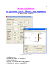
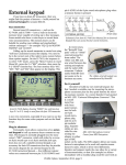
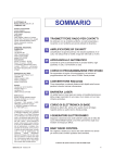
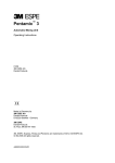
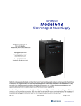
Simplified Instructions
for the
Better RF Automatic Screwdriver Control
The Better RF Automatic Screwdriver CONTROL consists of two separate, but interactive devices; The TUNE
CONTROL and the SCREWDRIVER CONTROL.
The TUNE CONTROL, which plugs into the back panel Tuner and CI-V Ports of an Icom IC-7000, contains a
microprocessor with on-board firmware and nonvolatile memory. It receives its logic power from the Icom
IC-7000, and communicates with the IC-7000 over the CI-V data port.
The SCREWDRIVER CONTROL interconnects with the TUNE CONTROL by way of a 2.5 mm stereo cable,
which also provides the logic power. It contains relays which activate the antenna motor, a PWM (Pulse Width
Modulator) which is used to slow the motor when required, an amplifier lockout relay, and a jack for the antenna
motor. The DC power for the antenna motor requires a fused, 3 amp circuit, which is the responsibility of the user.
These two devices, the TUNE CONTROL and the SCREWDRIVER CONTROL, should be viewed as a system.
While the TUNE CONTROL can be used as a stand-alone device, the SCREWDRIVER CONTROL cannot be
used as a stand-alone device.
The Icom IC-7000 provides the the necessary transmit power by utilizing the RTTY mode with a reduced carrier
(about 25 watts). It also supplies the TUNE CONTROL with an SWR readout, and acknowledgement of the
requisite button pushes required for Setup, and operation.
It is important to understand that the TUNE CONTROL/SCREWDRIVER CONTROL SYSTEM is not an antenna
tuner; it is an antenna CONTROL. With this in mind, there are several prerequisites which must be established
before installation and Setup can begin.
First, some methodology must be used to assure that the SWR is relatively low (<1.7:1). The best way to achieve
this is to use a base matching coil. Instructions for making one are included elsewhere in these instructions.
Remembering that the motor (and reed switch if so equipped) operate above RF ground. In other words, the leads
are RF hot anytime transmit power is applied to the antenna. This means some form of RF bypassing is required to
keep the RF off of the control leads. The requisite bypassing usually takes the form of ferrite beads, through which
the motor leads are wound. It is imperative that they are installed correctly. Instructions for doing so are included
elsewhere in these instructions.
Lastly, it is important to understand how the TUNE CONTROL/SCREWDRIVER CONTROL system responds to
the user with Beeps and Icons, and how it operates before any installation and Setup is attempted. Therefore, you
should read the entire instruction manual before starting installation and Setup. For brevity purposes, we’ll refer to
the TUNE CONTROL/SCREWDRIVER CONTROL SYSTEM as the TC/SC from here on out.
The BetterRF Company
44 Crestview Lane
Edgewood, NM 87015
505-286-3333 Voice
505-281-2820 Fax
7000 SCREWDRIVER Control
Table of Contents
Normal Operational Parameters .................................................................................... Page 1
Installation..................................................................................................................... Page 2
Setup.............................................................................................................................. Page 3
Setting the SWR Threshold........................................................................................... Page 4
Resetting to Factory Defaults ........................................................................................ Page 5
Operational Hints........................................................................................................... Page 6
Electrical Specifications ................................................................................................ Page 7
RF Bypassing Remotely Controller Antenna Leads ......................................................Page 7
Antenna Matching......................................................................................................... Page 8
Normal Operation
Beep response during Normal Operation is as follows. The level of the beep can be adjusted by changing the CW
sidetone level on the IC-7000. Refer the IC-7000 Owner’s Manual, page 43.
Single Beep: Response to the TUNER/CALL button, or the RESET button on the TUNE CONTROL.
Two Beeps: Indicates successful completion of any requested operation.
Three Beeps: Indicates that Setup has been entered.
Multiple Beeps: Indicates a failure to complete the requested operation.
Pressing the TUNER/CALL button on the IC-7000 very briefly (less than one second) will cause the antenna to
park. That is to say, it will move to the collapsed position, or highest frequency of operation, depending on the
model of the antenna. The IC-7000 does not transmit during this operation.
Pressing the TUNER/CALL button during the parking operation will stop the process. A second, brief press of the
TUNER/CALL button will resume the parking operation. A long press (at least one second) of the TUNER/
CALL button will reverse the motor direction.
Pressing the TUNER/CALL button on the IC-7000 for at least one second will cause the TC/SC to switch the
IC-7000 to RTTY at about 25 watts. Depending on the last frequency used, and the new frequency, the TC/SC will
check the SWR, and/or move the antenna as required to achieve an SWR below the preset level. Successful
operation, will turn on the TUNE indicator in the upper left corner of the IC-7000 display.
If it doesn’t find an SWR below the preset level, the TC/SC will search the entire range of motion two times for a
resonance. If it doesn’t find an SWR below the preset level, it will announce the failure with multiple beeps.
If it does find a resonance with an SWR below the preset level, the SWR is checked again. If it is not low enough
(perhaps due to over travel of the motor), the search is resumed at low speed in the opposite direction. Three retries
are allowed before failure is announced with multiple beeps.
It is imperative that the Setup instructions be closely followed if correct operation is to be achieved. Please read the
entire instruction manual before starting installation and Setup.
The first step is to change the programming switches (jumper pins on older models) to the correct positions.
Here are photos of the insides of the TUNE CONTROL showing the correct positions. Remove the two cover
screws, and orient the unit as shown in the photo. Move the switches or the jumper as indicated. Please make sure
the switches are correctly seated in the On/Off positions respectively. Failure to seat them properly will cause
erratic behavior of the TC/SC.
If you’ve been using the TUNE CONTROL with the Motor Control Lead, disconnect it from the motor leads and
discard it. It is no longer required for operation with the TC/SC.
Please note the two red dots on the CPU in the lower left corner. If yours has just one red dot, you have the original
firmware version. Differences in the Setup procedure for the original firmware version are noted in [brackets].
Requests for upgraded firmware should be sent to [email protected].
1
Installation
Some familiarity with the various menus functions of the Icom IC-7000 is required. If you don’t know what they
are, please refer to the Icom IC-7000 Owner’s Manual. Where applicable, page numbers have been listed for your
convenience. You might want to check off each item as it is completed.
Turn on the Icom IC-7000 and push the AF button momentarily. This places the IC-7000 in Setup mode. Push the
F-4 (OTH) button. Use the F-1 and F-2 buttons to select menu item #18 (PTT Start). Make sure it is set to OFF.
Use the F-1 and F-2 buttons to select menu item #48 (CI-V Baud Rate). Make sure it is set to AUTO. Use the F-1
and F-2 buttons to select menu item #49 (CI-V Address). Make sure it is set to 70h. Once the values are set, push
the AF button twice to return normal operation. These functions are explained on page 120, 131 and 136 of the
Icom IC-7000 Owner’s Manual. Please note: If the values are not set to OFF-AUTO-70h respectively, the TC/SC
will not function!
During programming of the TC/SC, it is necessary to view the SWR readout of the IC-7000. Here is how this is
done. Turn on the IC-7000. Press the MENU button for one second several times until the S submenu appears.
Press the F-3 (MET) momentarily until the SWR meter is displayed. You may return to any previous menu if
desired. This function is explained on page 36 of the Icom IC-7000 Owner’s Manual.
Make sure the IC-7000 is turned off. Plug the short 3.5 mm jumper cable into the CI-V port on the IC-7000. It is
labeled #5 on the diagram of the IC-7000 Owner’s Manual, on page 11. Next, plug in the TUNE CONTROL into
Tuner port on the rear apron of the IC-7000. Next, plug in the the other end of the short 3.5 mm jumper cable into
the bottom port on the TUNE CONTROL. Make sure the jumper cable is properly seated in both the IC-7000 and
the TUNE CONTOL. If it is not properly seated, the TC/SC will not work correctly.
The next step is to interconnect the TUNE CONTROL and the SCREWDRIVER CONTROL. Please make sure
the IC-7000 is turned off during this operation. Be advised, the stereo cable between the units supplies operating
power to the SCREWDRIVER CONTROL. Accidentally shorting this cable to ground could damage the TUNE
CONTROL.
Plug the 2.5 mm stereo cable into the SCREWDRIVER CONTROL. Make sure the cable is fully seated. Then plug
in the other end to the TUNE CONTROL. Please make sure the cable is fully seated. If an extension is needed, be
certain to use a shielded, stereo cable, such as Mouser Part Number 172-2535, or equivalent.
The TC/SC gets all of its logic power from the IC-7000. However, the IC-7000 cannot supply more than one amp
total from its accessory ports. Therefore, power for the antenna’s motor must be supplied by a separate, 3 amp,
fused, circuit. This is the user’s responsibility.
The ground side of the power cord (it has a spade lug already attached) must be connected directly to the chassis of
the IC-7000 using the grounding lug on the rear apron (see diagram on page 11 of the IC-7000 Owner’s Manual).
This is done to assure that the stall current is properly detected during Setup and operation. Failure to do so will
cause erratic behavior.
The power lead plugs into the port labeled +13.8 volts. Please use caution when doing so. If you attempt to force
the power lead, into the Motor port, the fuse could blow, and possibly damage the motor relays.
The supplied motor cable has a white, dashed line down one of the conductors. This lead is the center pin of the
connector. The dashed lead (center pin) should be connected to the antenna’s red motor lead. If you’re using a HiQ
antenna, connect the dashed lead (center pin) to the antenna’s black motor lead. The motor lead plugs into the port
labeled Motor.
The motion of the antenna should be checked before normal operation. If you get the wiring wrong, the direction of
travel is easily reset during Setup procedure.
The port labeled Amp, is a set of normally closed (NC) and normally open (NO) relay contacts. They’re used to
disable any amplifier during the tuning process. Typically, only the NC contacts will be used (left position of the
three pin jack). When tuning is in operation, the NC contacts open, removing the PTT from the amplifier. The
contacts are capable of handling up to 1 amp of current at 120 volts.
2
Once you’ve completed the installation, you may proceed to the actual Setup of the TC/SC which follows. To
reiterate, the antenna must be properly matched; the antenna’s motor control leads must be properly bypassed; and
the interconnect, DC, and motor wiring must be completed. Carefully recheck your wiring before proceeding to the
actual Setup.
Setup
There are several important points with respect to the Setup procedure. First, you should check off each step as you
do them. This will insure that each step is completed in the correct order. Each step maybe repeated as many times
as necessary. If you lose your place just turn off the Icom IC-7000, and start over. However, depending on which
operation was aborted, the RF power out may remain at 25 watts. This will require you to reset the SSB output
power level. Please refer to the IC-7000 Owner’s Manual, page 38.
Please note; if you have the original firmware version (one red dot on CPU), there are minor differences in the
Setup procedure. They are noted in [brackets].
1). Turn on the IC-7000. The next three steps will cause the IC-7000 to switch to the RTTY mode. The RTTY
mode will be used for setting the motor polarity, establishing the stall current threshold, and setting the SWR
threshold.
2). Hold the SPCH/LOCK button on the IC-7000 until the key icon appears on the IC-7000 screen [Hold the
RESET button]. Refer to the IC-7000 Owner’s Manual, Page 37.
3). Press the TUNER/CALL button. The IC-7000 will respond with three beeps [Release the RESET button]. If
you cannot make the TC/SC enter Set-Up in this manner, there are three items to check.
Make sure the short 3.5 mm jumper is securely plugged into the CI-V port, and into the TUNE CONTROL. Refer
to the diagram on page 11 of the IC-7000 Owner’s Manual. The CI-V Port is number 5.
Make sure the 2.5 mm stereo plugs are securely plugged in the TUNE Control and the SCREWDRIVER Control.
Make sure the TUNE CONTROL is securely plugged into the IC-7000 Tuner Port. Refer to the diagram on page 11
of the IC-7000 Owner’s Manual. The Tuner Port is number 6.
4). Hold the SPCH/LOCK button on the IC-7000 until the lock icon appears on the screen [Press the RESET
button]. Then release the button. The Lock icon will go out and the IC-7000 will issue one beep which indicates
that you are in the Checking Motor Polarity mode. The Lock icon is described on page 37 or the IC-7000 Owner’s
Manual.
5). Press the AF(Set) knob on the IC-7000 momentarily to enter the IC-7000 Set Mode. You may later return to the
normal screen by pressing the AF(Set) Knob twice.
6). Press F-1, QS (Quick Set) to enter the Quick Set Mode.
7). Press F-1 or F-2 to select Item 4, the RTTY Shift Width. It should read 200 Hz.
Refer to the IC-7000 Owner’s Manual, page 56. The RTTY Shift Width indication is used to manually control the
antenna motor. When 200 Hz is visible on the screen, the screwdriver motor is OFF.
8). Turning the VFO knob clockwise will change the RTTY Shift Width to 425. This should cause the antenna to
extend and move to a lower frequency. If you have a HiQ, the plunger will move down. If it moves in the correct
direction, return the RTTY Shift Width to 200 Hz to stop the motor, and go to step 11). If it does not move in the
correct direction, go to step 9).
9). Turning the VFO knob counterclockwise will change the RTTY Shift Width to 170. This should cause the
antenna to collapse and move to a higher frequency. If you have a HiQ, the plunger will move up. If it moves in the
correct direction, return the RTTY Shift Width to 200 Hz to stop the motor, and go to step 11). If it does not move
in the correct direction, go to step 10).
3
10). If the antenna moved in the wrong direction in step 8) or step 9), it can be reversed by pressing the SPCH/
LOCK button twice within a period of 2 seconds [Press the RESET button twice within 2 seconds]. The Lock icon
must appear with each button press [the Lock icon will not appear]. After pressing the SPCH/LOCK button twice
within a period of 2 seconds, go back to step 8), and/or step 9), and recheck to make sure the antenna moves in the
correct direction. If you cannot reverse the direction, go back to step 7).
11). Under certain circumstances, the TC/SC uses PWM (pulse width modulation) to slow the motor down.
However, some screwdriver motors do not run well at the 50% pulse width. If the motor moved correctly in step 8)
or 9), then move to step 13). If the motor did not move properly in steps 8) or 9), go to step 12).
12). The percentage on-time can be changed with the following procedure which may be repeated for a larger
effect. You must be in the Checking Motor Polarity mode.
Press F-1 or F-2 to select Item 3, RTTY Mark Frequency. The value 1615 Hz should be displayed.
To increase the percentage on-time by 10%, rotate the VFO knob clockwise to 2125 Hz. To decrease the
percentage of on-time, rotate the Main Tuning Dial counterclockwise from 1615 Hz to 1275 Hz.
PRESS F-2 to return to the RTTY Shift Width display and test the result as described using step 8) or step 9).
13). The TC/SC has a built-in Stall Current detection scheme. In order to assure correct operation, the ground lead
for the 13.8 vdc used to power the antenna motor, must be connected to the chassis of the IC-7000 as outlined
above.
With the TC/SC Checking Motor Polarity mode, rotate the Main Tuning Dial counterclockwise to retract the
antenna completely (highest frequency), and then stop the antenna motion by displaying 200 Hz. If you have a
HiQ, then the plunger should be all the way at the top.
If you have a HiQ, or other antenna with a built-in current limiter, wait about one minute before proceeding.
Next, hold the SPCH/LOCK button on the IC-7000 until the lock icon appears on the screen, then release the
button [Press the RESET button]. The antenna will extend (move to a lower frequency) for approximately 4
seconds, then retract (move to a higher frequency) for approximately 4 seconds, and then stall for 4 seconds. The
motor current is measured under these conditions, and an appropriate stall current threshold is calculated and
saved. A successful determination of the stall current threshold will be signaled by double beeps.
If you did not get the double beeps, the you need to repeat the Setup procedure beginning at step 1).
Setting the SWR Threshold
The TC/SC has a default SWR setting of 1.5:1 on each band. It maybe reset to a different value (up or down), and
may be different for each band. However, the input impedance of any HF mobile antenna is partially dependent on
the image plane losses which vary from location to location. Setting the SWR threshold too low at one location,
may cause erratic operation at another.
The SWR threshold procedure may be ended at any time by turning off the IC-7000, and any SWR value set so far
will be saved. However, depending on which operation was aborted, the RF power out may remain at 25 watts.
This will require you to reset the SSB output power level. Please refer to the IC-7000 Owner’s Manual, page 38.
You may repeat the SWR threshold procedure as often as necessary. It should be performed at periods of low band
activity, as the procedure involves transmitting on the air.
If your antenna is properly matched with a base matching coil, and the SWR is under 1.5:1, you needn’t reset the
default SWR setting of 1.5:1. Again, setting the SWR threshold too low could cause erratic operation.
4
14). If you wish to change the default SWR setting, turn off the IC-7000.
15). Turn the IC-7000, and place the TC/SC in the Setup mode mode as outlined in steps 1) through 3) above.
16). Select the band and frequency on the IC-7000 for which you wish to set the SWR threshold.
17). Press the TUNER/CALL button on the IC-7000 for at least one second. You’ll hear one Beep. The IC-7000
will transmit on the selected frequency in the RTTY mode at about 25 watts, and the RTTY Shift Width should be
displayed as described in steps 5), 6), and 7) above.
If the IC-7000 does not transmit when you push the TUNER/CALL button, it means you’re in the Stall Current
detection mode. If this occurs, turn off the IC-7000, and repeat step 1 through step 3).
18). Rotate the VFO knob counterclockwise (RTTY Shift Width 170 Hz) or clockwise (RTTY Shift Width 425 Hz),
to retract or extend the antenna (go higher or lower in frequency).
Watch the SWR meter, and when it dips to where you wish to set the threshold (not necessarily its lowest point),
stop the antenna motion by returning the VFO knob to its starting position of 200 Hz, as outlined in steps 8) and 9).
Depending on the band, you may have to jog the VFO knob back and forth several times to get to the desired SWR
threshold.
During the procedure, if you hear two sets of double beeps, that indicates the antenna has stalled at the end of
travel. You should then reverse the antenna motion.
19). Once the desired SWR threshold is met, press the SPCH/LOCK [TUNER/CALL] button for at least one
second. The IC-7000 will stop transmitting, and the SWR threshold will be stored.
The SWR threshold setting procedure may be repeated by choosing another band and frequency. When you’ve
finished, simple turn off the IC-7000.
This completes the Setup of the TC/SC. If the Setup procedure was performed correctly, the TC/SC will give you
years of trouble-free service. If erratic operation does occur, refer to the Operational Hints below.
Resetting to Factory Defaults
If you wish to return the TC/SC to its as-shipped, factory-default settings, here’s how to do it. However, doing so
will require you to go through the complete Setup procedure, from start to finish. If you do not, correct operation
will not be possible.
To reset the TC/SC to factory default, turn off the IC-7000. Press and hold the Reset button on the TUNE
CONTROL. If your IC-7000 is remotely mounted, this may require help.
Next, turn on the IC-7000, and release the Reset button. If the operation was successful, you will hear two beeps.
Normal operation may started immediately without turning off the IC-7000. Please remember, resetting the TC/SC
to Factory Default condition means you will need to reprogram the TC/SC in order to use it.
5
Operational Hints
What follows are a few anomalies which might crop up do to circumstances beyond our control. They are here to
help you solve erratic operational problems, whatever their cause.
The single biggest cause of erratic behavior, is inadequate RF bypassing of the motor leads. Please review the RF
Bypassing Remotely Controlled Antenna Leads below.
The second biggest cause of erratic behavior, is an inadequate image plane under the antenna. This causes RF to
flow over the motor leads (even when they are bypassed), over the outside of the coax (parallel line currents), and
into the vehicle wiring. As a result, additional bypassing of the leads in and out of the TC/SC may be necessary.
Split beads are your best bet. They should be installed on the power and motor control leads, and mounted close to
the TC/SC. For more information on split beads, review the RF Bypassing Remotely Controlled Antenna Leads
below.
Proper antenna matching is a prerequisite for full automatic use of the TC/SC. Although the SWR threshold maybe
reset higher than the factory default of 1.5:1, doing so points out the need for better impedance matching. Review
Antenna Matching below.
If you experience erratic operation at some remote locations, it is an indication that the threshold SWR is set too
low. Remember, the input impedance of any HF mobile antenna is partially dependent on the image plane losses
which vary from location to location. Setting the SWR threshold too low at one location, may cause erratic
operation at another. This often occurs when you set the SWR threshold while parked atop a steel reenforced,
concrete driveway.
Proper DC wiring is a must. You should never connect amateur radio equipment to existing vehicle wiring. Besides
inviting RFI issues, it can also cause ground loops to occur. Ground loops are the worst of maladies, as they appear
to be caused by RFI, when they’re not.
Manual operation of the antenna for the purposes of checking its capability of reaching adequately low SWR
values can be initiated by executing steps 1) through 3), and then proceeding directly to steps 15) through 18). To
check the SWR on another band, press the TUNER/CALL button for at least one second, and the IC-7000 will
stop transmitting This only works if you have the current firmware version. Also note, pressing the SPCH/LOCK
button will save the SWR value being displayed as the new SWR threshold for the current band as described in the
section on Setting the SWR Threshold.
Yes, it is possible to set menu item #18 (PTT Start) to On (Refer to IC-7000 Owner’s Manual, page 131), and
control the TC/SC by using the PTT. However, this will cause the TC/SC to transmit a 25 watt carrier, anytime the
frequency is changed more than 1%. This is an undesirable side effect, which should be avoided.
As pointed out above, aborting some operations could cause the RF power out to remain at 25 watts. This will
require you to reset the SSB output power level (please refer to the IC-7000 Owner’s Manual, page 38). It may also
cause the TUNE indicator (upper left hand corner of the IC-7000 display) to light. In this case, the indication is
false.
The 13.8 VDC user supplied circuit used to power the antenna’s motor, should be fused at 3 amps maximum.
Under no circumstances should it be connected to the accessory port, or Tune port, of the IC-7000. These ports are
rated at 1 amp maximum (total for both ports). Exceeding this will cause a circuit trace to fail long before the
IC-7000’s internal 5 amp fuse will blow.
6
Electrical Specifications
Current Drawn from IC-7000 Accessory Jacks: <100 mA.
Antenna Motor Power Feed: 13.8 VDC, Fused @ 3 Amperes (User Supplied)
Screwdriver Antenna Motor Running Current: 2.5 Amperes Maximum
Motor Stall Current Threshold: 3.5 Amperes Maximum (User Settable)
Motor Over Current Threshold: 3.5 Amperes
Nominal Pulse Width on Slow Motor Speed: 50% (User Settable)
Amplifier Control Current: 1 Ampere Maximum and 120 V Maximum
Maximum Number of Resonance Retries after Minimum SWR Found: 3
Maximum Number of Full Range Searches for Resonance: 2
IC-7000 CI-V Address: 70h
RF Bypassing Remotely Controlled Antenna Leads
Remotely controlled HF mobile antennas are very popular. Although they are commonly referred to as Screwdriver
Antennas, there are several different styles to choose from. The traditional screwdriver was conceived by Don
Johnson, W6AAQ, and there have been dozens of copies and variations of the scheme. The majority of them
change over all length as the frequency is varied.
Other designs like the HiQ do not change length. There's one made in Australia which is based loaded, but most
are a variation of center loading.
Controllers also come is different configurations. Some read the SWR from the radio like the TC/SC does, while
others have separate SWR detectors, or count the number of turns using a built-in reed switch. Some are manual,
and some are fully automatic, but none of them are RFI bullet proof!
The one thing all remotely tuned antennas share, is the fact their tuning motor (and reed switch if so equipped) is
operated above RF ground potential. This means there is RF impressed on the control wires anytime transmit
power is applied to the antenna. Whether the antenna is manually, or automatically controlled, some form of an RF
choke needs to be used. In most cases, the choke takes the form of a ferrite bead or toroid.
While controller and antenna manufacturers are very explicit about how these
chokes should be installed, very few of them are installed correctly. Add in a little
insult caused by improper mounting of the antenna in question (typically an
inadequate image plane under the antenna), and RFI problems abound. Let's take a
moment to look at ferrites.
Ferrites are mixtures of iron oxide and one or more metals typically manganese,
nickel, and zinc. Occasionally rare earths such as yttrium and scandium are also
added. They are not always or predominately iron oxide, and may contain “soft
iron” meaning magnetically soft not physically soft. They provide high magnetic
permeability and high resistivity, although some formulations (known as mixes)
are conductive.
Combined with a variety of stabilizers and binders they can be molded to just
about any desired shape, with toroids, bars and beads being the most common ones
encountered by amateurs. By selecting the right mixture of metals, initial permeabilities from 10 to as high as 5000
or more are easily obtained. The temperature coefficient can also be adjusted to meet a specific use.
For example, a mix 31 split bead has an initial permeability (expressed as ui) of 1,500 and a nominal operating
range of .01 to .1 MHz. When placed over a wire where there is RF energy flowing (between one and several
hundred megahertz), it is equivalent to placing an inductor and resistor in series with the wire for RF currents.
Depending on the frequency of the RF energy, the equivalent impedance can be as high as 50 ohms or more, yet
DC current can pass through unrestricted.
7
The resistance to the flow of RF current is closely tied to the linear inch of material parallel to and surrounding the
wire, and it goes up by the square of the number of turns. It is actually a complex impedance, with X decreasing
and R increasing with increasing frequency. At some frequency X=R (loss tangent equals effective permeability)
and the Q becomes unity [Q=1]). It is this property which makes their use in RFI suppression so ideal.
As emphasized above, the effectiveness is directly dependent on the number of turns through the ferrite material,
and the particular ferrite material in question. Unfortunately, most factory supplied ferrites are not specified as to
mix, but mix 31 is a good place to start.
So how many turns are needed? Assuming mix 31 ferrite material, a correctly installed antenna with an adequate
image plane under it, and low power (100 watts or so), 6 turns may prove adequate. However, 8 turns, and
preferable 10 turns, are required in most cases.
The major stumbling block to this is, antenna manufacturers tend to make their control leads rather short! This
requires adding length to the wires. Typically, size 20 is adequate for most mobile installations unless the runs are
long (i.e.: motor home or RV).
Many beads aren't large enough to take 8 or more turns, so what do you do? DX Engineering, Palomar-Engineers,
Amidon, and others carry mix 31 split beads. The .5 ID units are ideal in most case. However, if your wire size is
larger than size 20, then use the .75 ID units.
In extreme cases, it may be necessary to use a ferrite material with a higher ui. An FT114-61 toroid core will hold
15 turns of #20 Teflon® wire, and will provide a magnitude more bypassing than the aforementioned mix 31 cores.
Regardless of the number of turns your antenna manufacturer recommends, they don’t have any control over how
and where you mount your antenna. Thus, the higher above RF ground your antenna operates, the more RF flows
over the control wires, and even the outside of the coax (parallel line currents). This points out the need for proper
mounting. The rule of thumb is, it's the mass under the antenna, not along side, that counts!
The beads should be placed at the very base of the antenna. Think of it this way; any length of wire from the
antenna to the position of the bead, is part of the antenna, and has RF impressed on it!
In some cases (high power operation, poor mounting position or method, etc.), additional bypassing is required.
Shielding the control wires from the antenna to their entry into the vehicle, and bypassing them to ground with
parallel .1 and .01 ceramic caps adds a magnitude of RF suppression.
Since the reed switch (if equipped) isn’t use with the TC/SC, here’s a tip. Connect the leads from the reed switch
directly to the mast of the antenna. In this case, you won’t need any bypassing on these leads. Remember, they’re
already at the same RF potential as the antenna.
Antenna Matching
The TC/SC is not an antenna tuner; it is an antenna controller! Depending on the
antenna, its mounting location, and its mounting methodology, the input impedance
will vary between 18 and 50 ohms (80 through 10 meters). This represents an SWR
between 2.7:1 and 1:1. Therefore, some form of antenna impedance matching is
required in most cases. However, the matching device cannot be an external antenna
tuner.
A simple inductor, installed across the coax connections, will provide the needed
impedance transformation. Here’s how it works. A small amount of capacitance is
borrowed from the antenna (the antenna is tuned slightly above true resonance).
When combined with the inductance of the coil, they form a highpass LC network.
As the frequency increases, the effective impedance transformation decreases. This
provides a low SWR over the operating range of the antenna (typically less than
1.6:1 from 80 through 10 meters). The coil also DC grounds the antenna lessening
static build up.
8
The one shown is 9 turns, 1 inch inside diameter, and wound with #14 enameled wire. The coil needs to be about 1
uH, plus or minus, depending on the input impedance of the antenna, The inductance of the coil is changed by
adjusting the spacing between the turns. Properly adjusted, the SWR will be less than 1.6:1 over the antenna’s
operating range (typically, 80 through 10 meters).
The coil will have the greatest effect on 80 and 40 meters, so those bands should be used to adjust the coil’s
spacing. Although the procedure can be done with an SWR bridge, it is much easier to accomplish with an antenna
analyzer, like the MFJ 259B.
Once the best SWR is found for 80 meters, check the SWR on 40 meters. It may be necessary to compromise
between the two settings. Once a good compromise is found, check the SWR on 20 meters. It should be equal to,
or slightly below the previous measurements.
If the lowest obtainable SWR is in excess of 1.7:1, it is an indication that the image plane losses are high, and/or
there is excessive coupling of the antenna to the body of the vehicle. If the SWR is below 1.7:1 without any
matching, it is a sure sign your installation needs to be improved.
The key to efficient operation is to have the best possible image plane under the antenna. In other words, it is the
mass under the antenna, not along side, that counts. Mounting antennas atop long posts, trailer hitch extensions, or
other mounting schemes where the body of the vehicle is far removed from the base of the antenna, will yield less
than stellar results.
9