1
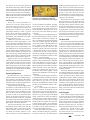
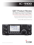
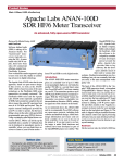
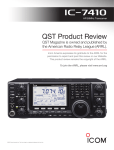
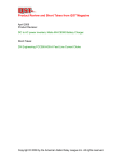
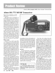
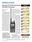
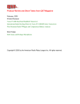
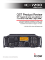
Key Measurements Summary PRODUCT REVIEW ICOM IC-7200 HF and 6 Meter Transceiver 137 138 140 20 70 20 kHz Blocking Gain Compression (dB) 82 2 83 70 140 2 kHz Blocking Gain Compression (dB) 100 I3 99 110 20 50 20 kHz 3rd-Order Dynamic Range (dB) I3 2 67 50 110 2 kHz 3rd-Order Dynamic Range (dB) 20 Reviewed by Steve Sant Andrea, AG1YK ARRL Assistant Editor The IC-7200 combines some of the IC7000’s brains with the IC-718’s brawn.1,2 With the ’7200, ICOM has created a transceiver with many of the digital features users expect in a modern radio, but packaged in a compact, rugged IC-718 size case that just begs to be taken along for the ride. With receiver coverage from 30 kHz to 60 MHz and transmitter coverage from 160 to 6 meters at 100 W in SSB, CW and RTTY and 25 W in AM, the IC-7200 will keep you on the air whether from home, car or boat. complexity beneath. Most of the buttons serve two functions. The primary function is selected with a short press of the button; the secondary function by holding it down for about a second. Each action, press or hold, activates a different set of functions. This control philosophy has been used on ICOM radios for quite a while and quickly becomes second nature. Additionally, ICOM has made the front panel water resistant. While not waterproof, it will tolerate an occasional blast of spray on your boat or a spilled coffee cup during a contest. The IC-7200’s front panel is neat and uncluttered. On the left are the front-firing speaker, microphone and headphone jacks and two dual function knobs. The center section contains the display, six function buttons and the main tuning dial. The right hand section contains a group of 17 buttons and a dual function knob. As with all microprocessor controlled radios, the number of controls belies the 1M. Wilson, K1RO, “ICOM IC-7000 HF/VHF/ UHF Transceiver,” Product Review, QST, May 2006, pp 64-71. QST Product Reviews are available on the Web at www.arrl.org/ members-only/prodrev/. 2S. Ford, WB8IMY, “ICOM IC-718 HF Trans ceiver,” Product Review, QST, Jul 2000, pp 63-67. The ’7200 runs on 13.8 V dc and requires about 20 A. A fused power cable is supplied. The radio incorporates an electronic keyer with the KEY jack on the rear panel. The external speaker jack accepts a 3.5 mm plug. A single SO-239 UHF connector is provided for the antenna connection. The rear panel has a bumper that protects the connectors from rough handling. Here’s a new feature: a universal serial bus (USB) interface. Transmit and receive audio can be sent over the USB interface, along with CI-V commands for transceiver control. In order to use the USB interface, you must download free driver software from ICOM, and a detailed manual is available too. This driver looks like a standard sound card to applications software, so your existing digital mode software should work Mark J. Wilson, K1RO Product Review Editor 23 +35 20 -40 20 kHz 3rd-Order Intercept (dBm) I3 2 -11 -40 +35 2 kHz 3rd-Order Intercept (dBm) I3 TX -20 -32 Transmit 3rd-Order IMD (dB) -35 I9 Rear Panel Front Panel I3 -58 TX -20 -70 Transmit 9th-order IMD (dB) pr037 80 M Key: Dynamic range and intercept values with preamp off. 20 M Intercept values were determined using -97 dBm reference Bottom Line The IC-7200 is a compact, easyto-operate HF and 6 meter transceiver that offers many features for voice, CW and digital mode operating. Rugged, water-resistant packaging makes it attractive for portable and emergency stations. [email protected] June 2009 51 with this interface — eliminating the need for an external computer/radio interface for digital modes such as PSK31 or RTTY. A traditional ICOM REMOTE jack provides another means for control of the ’7200 from your computer if you have the appropriate CI-V interface and software. Jacks for ALC (automatic level control) and SEND (TR relay control) are available for connection to a linear amplifier. A TUNER connector provides an interface to control an optional external antenna tuner. The ACC jack is a 13-pin connector that provides a transmit control line, a data line and keying line; ALC voltage line; a 1 A, 13.8 V dc output; RTTY keying control; a modulation input; an audio line output and a squelch control output. A matching plug is supplied with the ’7200, providing a set of color-coded pigtails for the accessory connector inputs and outputs. Band Selection The ’7200 includes a stacking register for each band, selected with the numeric keys. Holding the BAND button activates stacking register selection and the word BAND is displayed. Pressing the numeric key for the band you want will automatically set the active VFO to that band with the same configuration (frequency, mode, filter, preamplifier, and so on) that you last used on that band. The ’7200 has two separate VFOs (A/B) and a 7 + 1 digit frequency display (a 1 Hz digit is displayed in some situations). Frequency can be set manually with the main tuning dial or entered directly using the numeric keys. A one button equalizer copies VFO A into VFO B. While using the main tuning dial, there are three methods of controlling the tuning step (rate) of the main dial: tuning step, auto tuning step and 1⁄4 tuning function. The dial can also be locked by holding the SPCH button. The default is a 10 Hz step. Pressing the TS button activates the tun symbol. ing step, which is indicated by a Holding the button gives you the choice of five tuning steps: 0.1, 1, 5, 9 and 10 kHz. The auto tuning step function senses when you are rotating the main dial rapidly and increases the tuning step. This is convenient, for example, to move from the CW to the phone portion of the band more quickly. The auto tuning step speed varies between two and five times the normal rate, depending on its settings. Finally, the ’7200 includes a 1⁄4 tuning function used in the SSB data, CW and RTTY modes. While 1⁄4 tuning is active, the tuning step of the main dial is reduced to about 370 Hz per turn. This permits the precise tuning required by some digital modes. Direct frequency entry is activated by pressing the F-INP ENT button, entering the 52 June 2009 Table 1 ICOM IC-7200, serial number 0201073 Manufacturer’s Specifications Measured in the ARRL Lab Frequency coverage: Receive, 0.03-60 MHz; transmit, 1.8-2, 3.5-4, 5.3305, 5.3465, 5.3665, 5.3715, 5.4035, 7.0-7.3, 10.0-10.15, 14.0-14.35, 18.068-18.168, 21.0-21.45, 24.89-24.99, 28.0-29.7, 50-54 MHz. Receive and transmit, as specified. Reduced receiver sensitivity below 500 kHz.* Power requirement: 13.8 V dc ±15%; receive, 2 A (max audio); transmit, 22 A (100 W out). At 13.8 V dc: 1.15 A receive (max audio), 16.5 A transmit (100 W out). Operation confirmed at 11.7 V (max 75 W out). Modes of operation: SSB, CW, AM, RTTY. As specified. Receiver Receiver Dynamic Testing SSB/CW sensitivity, preamp on, filter shape Noise Floor (MDS), 500 Hz bandwidth: sharp,10 dB S/N: 1.8-29.7 MHz, <0.16 µV; Preamp off Preamp on 50-54 MHz, <0.13 µV. 1.0 MHz –121 dBm –131 dBm 3.5 MHz –131 dBm –141 dBm 14 MHz –132 dBm –141 dBm 50 MHz –135 dBm –142 dBm Noise figure: Not specified. 14 MHz, preamp off/on: 15/6 dB AM sensitivity, 10 dB S/N: 10 dB (S+N)/N, 1-kHz, 30% modulation: 0.5-1.799 MHz, <13 µV; 1.8-29.7 MHz, Preamp off Preamp on <2 µV; 50-54 MHz, <1 µV. 1.0 MHz 4.8 µV 1.5 µV 3.8 MHz 1.6 µV 0.5 µV 50 MHz 0.9 µV 0.4 µV Blocking gain compression: Not specified. Gain compression, 500 Hz bandwidth: 20 kHz offset 5/2 kHz offset Preamp off/on Preamp off 3.5 MHz 137/133 dB 101/82 dB 14 MHz 138/135 dB 102/83 dB 50 MHz 135/125 dB 89/76 dB Reciprocal Mixing (500 Hz BW): Not specified. 20/5/2 kHz offset: –103/–92/–85 dBc. ARRL Lab Two-Tone IMD Testing** Band/Preamp Spacing Input level 3.5 MHz/Off 20 kHz –31 dBm –19 dBm Measured Measured IMD level IMD DR –131 dBm 100 dB –97 dBm Calculated IP3 +19 dBm +20 dBm 14 MHz/Off 20 kHz –33 dBm –17 dBm 0 dBm –132 dBm 99 dB –97 dBm –51 dBm +17 dBm +23 dBm +26 dBm 14 MHz/On 20 kHz –44 dBm –25 dBm –141 dBm 97 dB –97 dBm +2 dBm +11 dBm 14 MHz/Off 5 kHz –49 dBm –34 dBm 0 dBm –132 dBm 83 dB –97 dBm –28 dBm –7 dBm –2 dBm +14 dBm 14 MHz/Off 2 kHz –65 dBm –36 dBm 0 dBm –132 dBm 67 dB –97 dBm –20 dBm –31 dBm –11 dBm +10 dBm 50 MHz/Off 20 kHz –34 dBm –22 dBm –135 dBm 101 dB –97 dBm +17 dBm +16 dBm Second-order intercept: Not specified. frequency and pressing the F-INP ENT again to set the active VFO to the entered frequency. If you make an error, pressing SET returns you to the previous frequency. The receiver incremental tuning (RIT) feature permits you to “trim up” the sound of a received signal to maximize readability. The RIT control is located at the lower right and can adjust the receive frequency about ±10 kHz. A final tuning aid is a band edge marker. When activated, the ’7200 will issue a beep Preamp off/on: +78/+78 dBm. whenever you cross the edge of the current amateur band. Modus Operandi The ’7200 has seven mode choices: LSB/USB, CW/CW-R (CW Reverse; shift to the opposite sideband), RTTY/RTTY-R and AM; FM is not included. Pressing the MODE button changes the operating mode in a circular fashion, LSB-CW-RTTY-AMLSB and so on. To access USB and the reverse modes, press MODE to select LSB, QS0906-Prodrev01 Receiver Receiver Dynamic Testing DSP noise reduction: Not specified. Variable, 10 dB maximum. Notch filter depth: Not specified. Manual notch: > 75 dB, Auto notch: 50 dB†; attack time 168 ms. S-meter sensitivity: Not specified. S9 signal at 14.2 MHz: preamp off, 67.8 µV; preamp on, 14.3 µV Squelch sensitivity; SSB: Not specified. At threshold, preamp on: SSB, 1.0 µV Receiver audio output: 2.0 W into 8 Ω at 10% THD. 2.3 W at 10% THD into 8 Ω. IF/audio response: SSB BW = 2.4 kHz: >2.4 kHz/–6 dB, 3.6 kHz/–60 dB; CW BW = 500 Hz: >500Hz/–6 dB, <900 Hz/–60 dB. Range at –6 dB points, (bandwidth):‡ CW (500 Hz): 384-816 Hz (522 Hz); Equivalent Rectangular BW: 486 Hz USB: (2.4 kHz) 279-2756 Hz (2477 Hz); LSB: (2.4 kHz) 273-2750 Hz (2477 Hz); AM: (6 kHz) 188-3049 Hz (2861 Hz). Spurious and image rejection: HF and 50 MHz: 50 MHz: >70 dB. First IF rejection, 14 MHz, 113 dB; 50 MHz, 94 dB; image rejection, 14 MHz, 62 dB; 50 MHz, 76 dB. Transmitter Power output: HF and 50 MHz: SSB, CW; 2-100 W; AM carrier power, 1-25 W. Transmitter Dynamic Testing SSB/CW, 1.4-103 W typical; AM, 0-28 W typical. Spurious-signal and harmonic suppression: >50 dB on HF, >63 dB on 50 MHz. HF, >57 dB; 50 MHz, 68 dB. Meets FCC requirements. SSB carrier suppression: >50 dB. >70 dB. -20 Undesired sideband suppression: >50 dB. >70 dB. -40 Third-order intermodulation distortion (IMD) products: Not specified. 3rd/5th/7th/9th order (worst case band): HF: –32/–31/–43/–58 dB PEP; 50 MHz: –30/–36/–44/–61 dB PEP. -60 CW keyer speed range: Not specified. 6 to 58 WPM. -80 CW keying characteristics: Not specified. See Figures 1 and 2. Transmit-receive turnaround time (PTT release to 50% audio output): Not specified. S9 signal, 30 ms. Unit is suitable for use on AMTOR. Receive-transmit turnaround time (tx delay): Not specified. SSB, 13 ms. Composite transmitted noise: Not specified. See Figure 3. Size (height, width, depth): 3.8 × 9.5 × 12 inches, incl protrusions, without rack handles. Weight: 12.1 pounds. Price: $1100. *Preamp off/on: 505 kHz, –121/–128 dBm; 137 kHz, –116/–95 dBm; 30 kHz, –77/–66 dBm. The preamp does not improve sensitivity below approximately 250 kHz. **Receiver testing was performed with the bandwidth set to 500 Hz and the filter shape to sharp. ARRL Product Review testing now includes Two-Tone IMD results at several signal levels. Two-Tone, 3rd-Order Dynamic Range figures comparable to previous reviews are shown on the first line in each group. The “IP3” column is the calculated Third-Order Intercept Point. Second-order intercept points were determined using –97 dBm reference. †Single beat note. Reduces two beat notes by 40 dB with attack time of 230 ms. ‡Default values, medium filter, sharp setting. Bandwidth is variable; smooth setting is available. CW bandwidth varies with PBT and pitch control settings. 0 0.01 0.02 0.03 0.04 0.05 0.06 0.07 0.08 TIME Figure 1 — CW keying waveform for the IC-7200 showing the first two dits in full-break-in (QSK) mode using external keying. Equivalent keying speed is 60 WPM. The upper trace is the actual key closure; the lower trace is the RF envelope. (Note that the first key closure starts at the left edge of the figure.) Horizontal divisions are 10 ms. The transceiver was being operated at 100 W output on the 14 MHz band. QS0906-Prodrev02 0 -100 14015 14017 14019 14021 14023 14025 Freq. Figure 2 — Spectral display of the IC7200 transmitter during keying sideband testing. Equivalent keying speed is 60 WPM using external keying. Spectrum analyzer resolution bandwidth is 10 Hz, and the sweep time is 30 seconds. The transmitter was being operated at 100 W PEP output on the 14 MHz band, and this plot shows the transmitter output ±5 kHz from the carrier. The reference level is 0 dBc, and the vertical scale is in dB. QS0906-Prodrev03 0 -20 -40 -60 -80 CW or RTTY and then hold MODE to access the alternate mode. For CW operation, pitch, sidetone level, key type, break-in type, keyer speed and CW sideband (LSB/USB) can all be configured. For RTTY, the ’7200 includes a twin peak filter, preset for 2125 Hz and 170 Hz shift; three FSK mark tones, four shift widths and selectable keying polarity are also available. To further improve the flexibility of the ’7200, each mode (SSB, CW, RTTY and AM) can be separately disabled. So, for ex- ample, if your operating style doesn’t include RTTY, you can disable it and it will not be included when stepping through the modes. The ’7200 also has a data mode for SSB and AM. When activated, the modulation for SSB and AM is taken from the MOD input of the accessory connector or the USB interface. CW-R and RTTY-R, once selected, will remain selected even after changing modes; SSB mode defaults to the normal mode, LSB on 160, 75/80 and 40 meters, USB elsewhere for each go-around. -100 -120 -140 -160 -180 1x10 2 1x10 3 1x10 4 1x10 5 1x10 6 Figure 3 — Spectral display of the IC-7200 transmitter output during composite-noise testing. Power output is 100 W on the 14 MHz band. The carrier, off the left edge of the plot, is not shown. This plot shows composite transmitted noise 100 Hz to 1 MHz from the carrier. The reference level is 0 dBc, and the vertical scale is in dB. June 2009 53 Keeping Track The IC-7200 is equipped with 201 memory channels. Channels 1 through 199 are memories that can store the transmit and receive frequencies and the operating mode. The remaining two (P1, P2) are band edge channels used as upper and lower frequency limits for the scanning feature. Programming the memory chan- Figure 4 — The rear panel of the IC-7200 includes nels is simple. In VFO mode, set antenna and power connectors, ALC and TR control your frequency, rotate the M-CH for a linear amplifier, provisions for digital modes and knob to select a channel and hold computer control. the MW (memory write) button. The ’7200 will respond with three beeps when the frequency is stored. That’s it! Now is where you find those items that change you never have to look up that net frequency often, RF power output or keyer speed for again. Programming memory channels in instance. QSM items vary according to the memory mode is similar except you first operating mode in use. Pressing SET opens select the channel to program and then set the QSM, and holding SET opens the SM. up the frequency. Interfering with Interference Recalling the channel is just as simple The ’7200 has many interference fighting — press the V/M button to activate the memory mode; MEMO will display. Use features, most of which use its digital signal the M-CH knob to select the channel you processing (DSP) system. The IF passband want and you’re there. In less time than it width is DSP controlled, according to the takes to say DX, the selected frequency is operating mode, from 50 Hz to 8000 Hz. transferred to the active VFO and you are Each mode has three filter widths — narrow, middle and wide. Each width is separately ready to radio! Once you have 201 frequencies stored, adjustable. I’m primarily a phone operator a scanner becomes a necessity. The ’7200 and found the default phone widths of 1800, is equipped with two scanning modes: pro- 2400 and 3000 Hz to be very good choices. grammed and memory. The programmed For those CW folks out there, the narrow CW scan uses the band edge channels ( P1 and filter default is 250 Hz. This is thoroughly P2) as its lower and upper limits, scanning up to date compared to the IC-718 with its each frequency between those two points. limited selection of optional crystal filters The memory scan steps through only those and DSP add-on for notch filter and noise frequencies stored in memory channels. It reduction starts from the lowest programmed channel and continues to the highest, then jumps back Passband Tuning The DSP passband tuning (PBT) feature and starts over. When it reaches an active frequency, it allows you to shift the entire IF passband stops. The scan resume function controls slightly higher or lower in frequency or to the stop time. With scan resume OFF, the narrow and enlarge the passband width. PBT is controlled by the TWIN PBT dual scan stops at the first active frequency and the scan is canceled. If scan resume is ON, knob located on the upper left of the front the scan will stop on the active frequency panel. The inner knob adjusts PBT1 (the and wait. If the frequency remains active for high frequency edge of the passband) and 10 seconds or goes quiet for 2 seconds, the the outer knob PBT2 (the low frequency edge). The manual’s description of the PBT scan will resume. is somewhat thin, so some clarification is Configuring the Radio in order. The neutral position for the PBT is with There are many aspects of the ’7200’s operation that can be customized to meet both the inner and outer knobs at detent. In your operating style. The Set Mode (SM) this position the IF passband is centered on menu is where you convert the stock radio the IF frequency and the width is set to the into your radio. The Set Mode includes 41 filter passband width setting. If you move items that are of the set-and-forget type. both knobs simultaneously counterclockThis is where you adjust settings such as wise (ccw), you move the passband lower LCD backlighting, meter peak hold and the in frequency without changing its width. Moving both knobs clockwise (cw) shifts internal keyer’s dot/dash ratio. There is also a Quick Set Mode (QSM) the entire passband higher in frequency. in addition to the regular set mode. QSM So if an interfering station appears slightly 54 June 2009 below your receive frequency, rotating both knobs cw will move the passband higher in frequency, eliminating the interfering signal. The width of the passband can be changed by adjusting the knobs separately. If you turn the inner (high edge) knob cw you are raising the upper frequency limit — widening the passband. If you turn the outer (low edge) knob cw you are raising the lower frequency limit — narrowing the passband. Notch Filters The automatic and manual notch filters are DSP functions used to notch out a very narrow sliver from within the IF passband. This allows you to remove an interfering carrier that is too close to your desired signal for PBT manipulations to eliminate. The digital notch filters are more useful against heterodynes, CW and digital signals than voice modulation. The automatic notch filter (ANF) scans the IF passband, detects up to two interfering signals and notches them out with between 40 and 50 dB of attenuation. The ANF will also track interfering signals as they move across the passband. The manual notch filter (MNF) is operator controlled using the MNF knob at the lower right. You rotate the knob, moving a stationary notch of 75 dB attenuation across the passband, until the interfering signal is removed. The MNF can only notch one signal at a time and will not track a moving signal, but it provides a noticeably deeper notch. The width of the MNF can be adjusted. The ANF and MNF cannot be used together. Noise Reduction The DSP noise reduction (NR) feature distinguishes between noise and a signal and then acts, digitally, to reduce the noise with minimal effect on the signal. It will only take one evening of operating on 80 or 160 meters to appreciate its usefulness. With a signal tuned in, just press the NR button to activate the feature, and then hold NR to open the adjusting menu. Turning the dial will vary the NR value between 0 and 15. Don’t be tempted to crank the NR up to 15 and just leave it there, though. At low levels of NR, audio quality is not affected, but at the higher levels some audio quality will be lost. Begin with the lowest level of NR and raise it to get the best balance between noise and readability. Last but not least is the noise blanker (NB) This is the great granddaddy of all noise controls and limits pulse type noise. The NB will act on any strong signal and will distort a loud, nearby station so it should only be used when needed. The ’7200’s NB has two adjustments, level and width. These can be accessed directly from the NB key. NB level sets the level above which the DSP blanks out the noise spike; NB width sets the time the attenuation is applied. Lab Testing The bar for receiver performance in transceivers at all price points has been raised in the nine years since we reviewed the IC-718. Although test procedures and reporting have changed as well, checking comparable numbers in Table 1 against the IC-718 lab tests shows significant improvement in the IC-7200’s dynamic range performance. The transmitter’s third-order IMD is improved as well. ARRL Test Engineer Bob Allison, WB1GCM, took this opportunity to visit Synergy Microwave and check the accuracy of the Lab’s HP-3048 Phase Noise Test System against newer instrumentation. Dr Ulrich Rohde, N1UL (Synergy Microwave founder and chairman), and Michael Tracy, KC1SX (former ARRL test engineer and now on the Synergy staff) found good correlation between their equipment and the ARRL Lab test results shown in Figure 3. Regular readers of this column will remember that Dr Rohde donated the HP3048 to ARRL to replace the Lab’s original setup, which was nearly 20 years old. (See May 2006 QST, page 70, for details.) ARRL greatly appreciates the technical assistance, consultation and equipment that Dr Rohde has provided over many years. Operating Experience My HF station uses a wire antenna and manual antenna tuner for multiband operation. I set the IC-7200 output to 20 W during adjustment, and the radio didn’t seem to be disturbed by the momentary high SWR my antenna presents on some bands. I began operating using the supplied hand microphone. I set the internal meter to ALC and found the audio was very low at the default setting of 50%. Ultimately I found that I needed to raise the microphone gain to 100% in order to get reasonable audio reports. At this point I decided to try using the internal speech compressor. I adjusted the compressor per the manual instructions operating into a dummy load and found that audio reports were much improved. This issue also affects the voice operated transmitting (VOX) feature. Even with the VOX GAIN at 100% I still had to hold the hand microphone within a few inches of my mouth for reliable operation. I also noted a tendency to hit the UP/DN buttons Figure 5 — The IC-7200’s amber display is small but very readable. It includes indicators for often-used features and settings. on the microphone accidentally changing the frequency; this is further complicated by the fact that the dial lock doesn’t lock the UP/DN buttons, although if set to act as a keyer, they will not do anything except in CW mode. When trying CW I was flummoxed since keying the transmitter produced a sidetone but no output. I checked my cabling to be sure no problem had developed and found none. A few minutes digging in the manual revealed the solution. The default mode for CW is break-in OFF. With break-in OFF, an outboard TR switch (such as a foot switch) is required. The switch connection is prominently displayed in the manual’s “Connections for CW” section. Having used the rig on SSB, I just plugged in a key expecting to configure the CW later. Lesson learned — read your manual. The ’7200 will accept straight key, bug or paddles. It has an internal keyer adjustable from 6 to 60 WPM, or you can use your favorite external keyer or computer software. While operating in either break-in mode, the clatter of the TR relay is quite noticeable. If you enjoy operating CW at speeds over 20 WPM in full break-in (QSK), I would suggest using headphones and closing the shack door. For DXing, split frequency operation is accomplished using two buttons. Just tune in the DX station on VFO A and hold the SPLIT button to copy VFO A to VFO B. Then press the A/B button to display VFO B and tune it to the transmit frequency. That’s it — you’re split. The 1 × 2.5 inch amber LCD is similar to the IC-718’s display. It’s definitely not the dazzling full color screen found on the IC7000, but it’s readable without difficulty and contrast is very good using the LO backlight setting. I found the HI setting too bright for indoor use, but for outdoor, bright sun venues it would probably be fine. The front-firing speaker produces unusually clear sound for a small, internal speaker. As an added aid, pressing the SPCH button generates a female voice that recites the radio’s frequency, received signal strength and mode. The IC-7200’s utility as a portable rig will make it a good fit for emergency operations. I found its controls easy to understand and had the rig operating fairly quickly. A “cheat sheet” of basic procedures in the hands of an operator experienced with modern transceivers should allow them to get to their mission quickly. I must stress, however, that the ’7200 should have its settings configured before the emergency as these settings greatly impact the rig’s operation. Thermal issues need to be kept in mind when operating the ’7200. When operating high duty cycle modes, the heat sink on the rear panel will get quite hot. The fan is audi ble but quiet and produces a brisk air flow. ICOM says it is normal for the radio to get hot during high duty cycle modes and the radio does not require a reduction in power output. The transceiver includes thermal protection so that if the radio senses it is getting too hot, the drive is reduced automatically. The Hard Stuff The IC-7200 includes a hardcopy manual, which gives you a firm grounding in the transceiver’s operation. The manual is of the cookbook variety that explains how to wire up the ’7200 for various types of operation and options, basic operating procedures for getting on the air, advanced procedures to guide you with its finer points and general information about programmable features and troubleshooting. The manual includes little snippets of theory but primarily consists of the step-by-step operating procedures. The procedures are straightforward and include illustrations of the controls used, the displays that should appear and, in some cases, additional diagrams to help explain a particular function. It does lack directions for the initial setup. I would suggest that once wired up, you start by reviewing the “Basic Operations” chapter to get a quick feel for the rig. When you are comfortable, hook up a dummy load and go to the “Receive and Transmit” chapter, then follow the referenced procedures to set up such basics as microphone gain, compressor level, CW pitch and other necessary adjustments for the modes you operate. This will make your initial excursions onto the bands much more enjoyable. Last Thoughts The IC-7200 is a rugged, compact rig that is packed with more digital flexibility than can be discussed here. It is well suited for portable operations and will make a good HF solution for your EmComm group. It should also be considered for recreational vehicle or apartment locations where its solid performance and small footprint will be an asset. Manufacturer: ICOM America, 2380 116th Ave NE, Bellevue, WA 98004; tel 800-872-4266, fax 425-454-1509, www.icomamerica.com. June 2009 55