1
Tau-PCI/32
Tau-PCI/32-Lite
Adapters for PCI-bus
One or two E1/PCM-30 interfaces,
built-in cross connector,
up to 32 data links,
up to 2048 Kbps
User Manual
Copyright © 2004-2007 Cronyx
Version 1.3, June 2007
Tau-PCI/32 Adapter, User Manual
Table of Contents
Specifications ............................................................................................................ 3
G.703 (PCM-30) Interface...................................................................................... 3
Description................................................................................................................. 3
Key Features ........................................................................................................... 4
Available Options ................................................................................................... 4
Deliverables ............................................................................................................ 5
E1 Line Protection .................................................................................................. 5
Interior Design of the Adapter................................................................................ 5
Adapter Installation ................................................................................................... 8
Adapter Check ........................................................................................................ 9
Software Installation............................................................................................... 9
Adapter Configuration in Linux ........................................................................... 10
Adapter Configuration in OS FreeBSD................................................................ 10
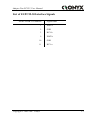
List of E1/PCM-30 Interface Signals ...................................................................... 11
E1
E1, Channel 1
E1, Channel 0
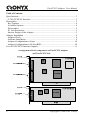
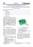
Arrangement of basic components on Tau-PCI/32 adapters
and Tau-PCI/32-Lite:
2
Copyright © 2004-2007 Cronyx
Adapter Tau-PCI/32, User Manual
Specifications
Bus Type......................................................PCI 2.1, 33MHz, 32 bits, 5V power supply;
Size ..............................................................160 x 125 mm;
Power Consumption ....................................3W or less;
Data Transmission Links.............................up to 32 independent logical channels from
E1/PCM-30 timeslots, total up to 2048 Kpbs;
Cross Connector ..........................................nonblocking, for three points (two E1
interfaces and transceiver);
Synchronous Protocols ................................HDLC, "transparent", V.110, X.30, ECMA
102, CCIT I4.53 RA2, GSM 08.60 TRAU;
Drivers for Operating Systems ....................Linux 2.4.x and 2.6.x; FreeBSD 4.x, 5.x and
6.x; Windows 2000/XP/2003;
Network Protocols .......................................PPP, Cisco/HDLC, FrameRelay;
G.703 (PCM-30) Interface
Data Transmission Rate...............................up to 1984 Kpbs (Nx64 Kpbs) (framed mode)
and 2048, 1024, 512, 256, 128 or 64 Kbps
(unframed mode), software selectable for
each interface;
Generator Stability.......................................50 ppm;
Line Coding .................................................AMI or HDB3, software selectable for each
interface;
Line Impedance ...........................................120 Ohms twisted pair, for coaxial cable
connection an external impedance matching
device is needed;
E1 Receiver Sensitivity ...............................0 to -12dB or to -43dB (up to 2.5 km of a
twisted-pair cable with wire section of
0.6mm2), software selectable;
Jitter Suppression.........................................in the reception path, 128 bit depth;
Frame and Multiframe Structure .................G.704, CAS, CRC4;
Frequency Offset Adjustment......................Controlled Frame Slip
Error Detection ............................................Impaired encoding, checksum CRC-CCITT;
Description
Tau-PCI/32 adapter is a multiplexer/cross-connector with two E1 ports and 32 builtin HDLC controllers. The adapter is installed in a computer with a PCI bus. The
Tau-PCI/32-Lite is a light version, has one E1 port and a compact design that allows it to
be installed in a Low-Profile PCI.
Copyright © 2004-2007 Cronyx
3
Tau-PCI/32 Adapter, User Manual
The Tau-PCI/32 adapter is primarily used in the construction of data transmission
networks based on E1 channels, and for the creation of specialized E1 flow processing
equipment (telephony, signaling).
The adapter delivery set includes operating system drivers that implement the
primary operation modes of the adapter, which are enough to construct data transmission
networks. A driver and other specialized software development library (DDK - Driver
Development Kit) will be supplied to deliver required enhanced functionality.
Key Features
Two E1 interfaces with high-sensitivity receivers;
Up to 32 independent logical synchronous data transmission channels;
Built-in cross connector of timeslots and CAS signaling;
CAS signaling maintenance block, Sa-bit switch;
HDLC support, "transparent" mode, V.110/X.30, bit order inversion;
Low-level interaction with E1-interface;
Built-in scrambler, bit rate slow-down modes;
PCI bus-master;
DDK (Driver Development Kit);
Available Options
The Tau-PCI/32 adapter has two models;
Tau-PCI/32 – two E1/PCM-30 interfaces;
Tau-PCI/32-Lite – one E1/PCM-30 interface and no CAS signaling
maintenance block;
4
Copyright © 2004-2007 Cronyx
Adapter Tau-PCI/32, User Manual
Deliverables
Tau-PCI/32 Adapter Board;
Two floppy disks or a CD-ROM with software;
User Manual;
Loopback plug for E1 interfaces testing;
Depending on the model, one or two DB15 connectors (male in case) for E1 lines
connection;
E1 Line Protection
Data transmission lines can be subjected to pulse disturbances generated by
electrostatic discharges, lightning and other sources.
The interface part of the E1 channels contains safety fuses and TVS matrices that
provide secondary protection of the adapter. The adapter interfaces must be additionally
fitted with primary protection devices if you use long E1 lines stretching beyond single
building.
Devices that can be used for the primary protection of E1 lines have the rated
breakdown voltage of about 7.5V and the tolerated pulse current of 200A, and small selfcapacitance.
Interior Design of the Adapter
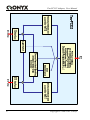
Functionally, the Tau-PCI/32 adapter can be divided into six primary structural parts:
A transceiver that simultaneously maintains up to 32 logical channels from E1
timeslots;
E1 line interfaces; two or one interfaces can be installed depending on the adapter
model;
A nonblocking cross-connector that performs random cross switching of timeslots
between three "points": a transceiver and two E1 interfaces;
An on/off shaper of channel associated signaling (CAS) data, which allows the use
of timeslot 16 to exchange CAS signaling data, adjusted for cross switching
(absent from Tau-PCI/32-Lite);
An on/off switch of Sa-bits (Sa4…Sa8) that enables the use of timeslot 0 of the
transceiver for Sa bits exchange, and simultaneously allows Sa bits to bypass the
E1 interfaces;
On/off modules to support the unstructured mode, and scramblers for each E1
interface;
Copyright © 2004-2007 Cronyx
5
Tau-PCI/32 Adapter, User Manual
6
Copyright © 2004-2007 Cronyx
Adapter Tau-PCI/32, User Manual
The transceiver provides exchange (reception/transmission) of information between
the “logical channels” and RAM via the PCI bus. The logical channels of the transceiver
are formed from the predefined E1 timeslots. Each timeslot can be "connected" to only
one logical channel. This allows up to 32 logical channels to be obtained. The exchange
of the data in the logical channel is a synchronous process that occurs at a speed
dependent on the number of the connected timeslots (unbalanced as an option). For each
logical channel, defined are a channel protocol (HDLC, transparent mode, etc.) and a
specific reception and transmission order; each channel can be started and suspended
independently of the others.
The on/off CAS signaling maintenance block allows you to implement associated
channel signaling processing adjusted for cross switching. The CAS maintenance block
exchanges data with the transceiver using timeslot 16, and, on the other hand, interacts
with the cross connector using a separate parallel data bus. The CAS maintenance block
is not included in the Tau-PCI/32-Lite, because its functionality becomes redundant and
unrequested with only one E1 interface available.
The nonblocking cross-connector allows you to set an “incoming” source for each
“outgoing” timeslot. This allows you to randomly switch and rearrange timeslots, provide
digital loops etc. The cross switching matrix is updated at the E1 frame border. In
addition to the data, the cross connector concurrently processes CAS signaling.
The use of the CAS maintenance block simultaneously to the activation of signaling
exchange at E1 interfaces produces full-value, three points cross switching of both
timeslots and CAS signaling.
An on/off switch of Sa-bits (Sa4 … Sa8) allows you to arrange
reception/transmission of Sa-bit values and enable them to be exchanged between E1
interfaces. The Sa-bit switch exchanges data with the transceiver via timeslot 0, and, on
the other hand, interacts directly with the E1 interfaces.
The on/off modules for supporting the unstructured mode for each E1 interface are
balanced type and controlled independently. The “unstructured” mode means that the E1
data flow does not have a frame structure according to ITU-T G.704, at the same time
data is transmitted in a synchronous bit flow at 2048 Kbps, and the borders of the
timeslots are not defined. Correspondingly, cross connector, CAS maintenance block and
Sa-bit switch become useless.
The activation of the unstructured mode at 2048 Kbps at one of the E1 interfaces (no
bit rate slow-down, see below) results in the engagement of all the transceiver timeslots.
The exchange of data with the other E1 interface and other functional blocks in the
adapter becomes impossible. Correspondingly, one logical channel for all timeslots must
be activated in the transceiver.
For compatibility with other equipment by Cronyx, the adapter supports scrambler
and multiple bit rate slow-down modes (2x, 4x, 8x, 16x and 32x). Simultaneously, the
physical data transmission rate always remains 2048 Kbps, only the useful transmission
rate changes.
Copyright © 2004-2007 Cronyx
7
Tau-PCI/32 Adapter, User Manual
Not all of the 32 transceiver timeslots are used in the unstructured bit rate slow-down
modes. The control modules are assigned to timeslots that should be used, and their
number must correspond to the speed selected. The indicated timeslots are disconnected
from the cross connector, and are only used by the unstructured mode modules.
The activation of the unstructured mode results in the data bus of the corresponding
E1 interface switching from the cross connector to the control module. The exchange of
Sa bits and CAS signaling does not make sense any longer, this data will be ignored by
the E1 interface.
The timeslots that are not used by the unstructured mode of the E1 interface can be
used randomly. Such uses include interacting with the other E1 interface, both in the
structured and unstructured modes.
The transceiver, the cross connector and other functional parts of the adapter are
always synchronized from the same source. The reception path of either E1 interface or
the internal adapter clock can be used as such a source. If clock signals from the external
source are lost, the adapter always automatically switches to the internal clock.
Only the basic operation modes needed to construct packet transmission networks are
implemented in the supplied drivers. To use the other features of the Tau-PCI/32 adapter,
you may have to use the Driver Development Kit (DDK).
For additional information, please refer to the support service and DDK
documentation.
Adapter Installation
Before installation, make sure that the power supply unit of your computer has
enough power to support the Tau-PCI/32 adapter.
Make sure your computer is switched off! Most of the modern computers must
be disconnected from external power supply, otherwise, the PCI bus and some
other components would be live!
Remove the cabinet cover, find vacant PCI slot and remove the related plug on
the rear side of the chassis;
Insert the adapter into the PCI slot up to the stop and screw it tight to the rear
side of the chassis;
Connect E1 lines to the DB-15 connector (see the "List of E1 Interface
Signals" section). While soldering, make sure the residual flux did not
contaminate the contact surfaces;
Replace the cabinet cover;
Connect the communications equipment using appropriate cables (not
included);
8
Copyright © 2004-2007 Cronyx
Adapter Tau-PCI/32, User Manual
Adapter Check
The adapter delivery set includes two 3.5” floppies or a CD-ROM. If floppy disks are
included, boot up the computer using the “Diagnostic Boot” floppy, otherwise boot up
from the CD-ROM.
After the boot, a diagnostic application that will start automatically will search and
perform basic testing of the internal circuits (bus test) of the installed adapters. Then, you
choose the adapter that needs testing.
The diagnostic application allows you to run various tests, which involve the use of
appropriate external equipment and/or E1 interface loopbacks.
For most cases, the following steps will be sufficient to check the availability of the
adapter:
Access the Test menu and run the General Test command;
For complete check of the protection circuits and E1 interface health:
Access the Cross Connector menu and run the Enable E1/0 command;
Connect the external loopback (supplied) to the E1/0 interface;
Access the Test menu and run the Receive/Transmit command;
For dual-interface models, the same sequence can be performed to test the second
E1/1 interface.
If the equipment has been connected correctly and is functional, each test must yield
no errors (with allowance for several start errors due to synchronization adjustment).
For instructions that are more detailed please refer to the support service.
Software Installation
The adapter delivery set includes two 3.5” floppy disks or CD-ROM. If floppy disks
are included, one contains a testing application and is a boot floppy (labeled "Diagnostic
Boot"), and the other contains drivers for the supported operating systems.
If floppy disks are included, the drivers for FreeBSD and Linux can be found on the
second floppy. Drivers for any version Windows are not available. The readme.txt file
contains a full list of the drivers. You can read the floppy files using the "mread" utility
("mtools" package). To unpack, use "tar" utility. For example:
mread a: clinux445.tgz
tar xvzf clinux445.tgz
After unpacking, install the driver according to the instructions contained in the
readme.txt file. For the latest drivers and other accompanying software, you should visit
the Cronyx website. Before you install the software, please read all of the attached
documentation carefully.
Copyright © 2004-2007 Cronyx
9
Tau-PCI/32 Adapter, User Manual
Adapter Configuration in Linux
After the kernel modules (drivers) are assembled and installed, a startup module
launch and channel configuration command file will also be installed. Because different
Linux clones use a distinct startup procedure, for some systems this command file has to
be installed manually (also, modification of the command file itself may be required).
When prepared command file is used, to change the channel operation parameters the
/etc/cronyx.conf file has to be edited and the modules – restarted.
To set up the Tau-PCI/32 adapter modes, the sconfig utility (which is used for other
Cronyx adapters) is used in OS Linux. It is recommended to create a command file,
which sets the operation modes for the channels during the OS startup by using the
examples supplied in the distribution kit. To get brief help about the sconfig utility, you
can run the following command
sconfig help
A full description of the sconfig utility is supplied as part of the software
deliverables, see «man sconfig».
To understand the syntax of the /etc/cronyx.conf configuration file, you should also
refer to the description of the sconfig utility, which is largely similar to the syntax of this
utility’s parameters.
Adapter Configuration in OS FreeBSD
To set up the Tau-PCI/32 adapter modes, the sconfig utility, which is used for other
Cronyx adapters, is used in OS FreeBSD.
Typically, the modes are set during the operating system startup, e.g., from the /etc/rc
file, and remain the same in the future. To get brief help about the sconfig utility, you can
run the following command
sconfig help
A full description of the sconfig utility is supplied as part of the software
deliverables, see «man sconfig».
10
Copyright © 2004-2007 Cronyx
Adapter Tau-PCI/32, User Manual
List of E1/PCM-30 Interface Signals
Pin No. in DB-15 Connector
Signal Name
1
XMT-a
2
GND
3
RCV-b
9
XMT-b
10
GND
11
RCV-a
Copyright © 2004-2007 Cronyx
11
Support Service of KB Cronyx:
Telephone: +7 (499) 946-99-90
[email protected]
E-mail:
Website:
http://www.cronyx.ru
ftp://ftp.cronyx.ru
KB Cronyx Office and Sales Department:
Telephone: +7 (495) 742-17-71
Fax:
+7 (495) 742-17-73
E-mail:
[email protected]
http://www.cronyx.ru/price
Prices:
Please send all requests and remarks regarding this manual and the use of the software at
[email protected]
С уважением,
Леонид Юрьев <[email protected]>, КБ Кроникс.
Cronyx Engineering
КБ Кроникс
4, Marshal Sokolovsky street,
Moscow, Russian Federation,
123060
+7 (495) 742-17-71
http://www.cronyx.ru
ftp://ftp.cronyx.ru
123060, Российская Федерация,
[email protected]
Москва, ул. Маршала
Соколовского, дом 4
Copyright © 2004-2007 Cronyx