1
OWNER’S
MANUAL
Robert H Peterson Co.
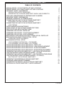
MANUAL & REMOTE-OPERATED
OUTDOOR CAMPFYRE™
RHP
Manual control
panel
Remote
control
Remote Unit
Control Panel
FOR OUTDOOR USE ONLY
For all OC-34 Series Outdoor Campfyres™
Important: Read these instructions carefully before
CODE AND SUPPLY REQUIREMENTS:
starting installation of the Outdoor
Campfyre™.
This Outdoor Campfyre ™ must be installed in
accordance with local codes and ordinances, or, in
the absence of local codes, with the latest National
Fuel Gas Code, ANSI Z223.1.
WARNING
Improper installation, adjustment, alteration, service,
or maintenance can cause property damage, personal
injury, or loss of life. Refer to this manual. For assistance
or additional information, consult a qualified professional
installer, service agency, or the gas supplier.
FOR YOUR SAFETY, IF YOU SMELL GAS:
1. Shut off the gas to the appliance.
2. Extinguish any open flame.
3. If odor continues, immediately call the gas
supplier or the fire department.
This appliance is designed as an attended appliance.
Adults must be present when the unit is operating.
DO NOT leave this unit burning when unattended. If
this product is left burning unattended, it may cause
damage or serious injury.
FOR YOUR SAFETY
1. Do not store or use gasoline or other flammable
vapors and liquids in the vicinity of this or any
other appliance.
Important: For safe operation and proper
performance of this product and to
comply with certification, listings,
and building code acceptances, use
ONLY Peterson Real-Fyre® controls,
parts, and accessories that have
been specifically listed or certified for
use with this burner system. Use of
other controls, parts, or accessories is
prohibited and will void all warranties,
certifications, listings, and building
code approvals, and may cause
property damage, personal injury, and
loss of life.
2. A propane cylinder not connected for use shall
not be stored in the vicinity of this or any other
appliance.
Installation and service must be performed by
an NFI Certified or other qualified professional
installer, service agency, or the gas supplier.
INSTALLER & CONSUMER
These instructions MUST be retained with this
appliance for future reference.
Certified to
CSA International 4.96 US for
outdoor gas fireplaces
ROBERT H. PETERSON CO. • 14724 East Proctor Avenue • City of Industry, CA 91746
REV 10 - 0710110811
1
L-A2-18207
RHP
Robert H Peterson Co.
MANUEL & CAMPFYRE DE PLEIN
AIR OPÉRÉ ÉLOIGNÉ
Tableau de
bord manuel
MANUEL
OWNERS
Tableau de bord de
l’Unité éloigné
Télécommande
POUR USAGE DE PLEIN AIR SEULEMENT
Pour toute l’oc-34 série Campfyres extérieur
CODE ET EXIGENCES DE LA PROVISION:
Ce Campfyre De plein air ™ doit être installé
conformément à codes locaux et ordonnances, ou
dans l’absence de codes locaux, avec le Code du Gaz
du Combustible National le plus tardif, ANSI Z223.1.
IMPORTANT: LISEZ AVEC SOIN CES
DIRECTIVES AVANT INSTALLATION
INITIALE DE VOTRE ENSEMBLE DE LA
GROSSE BÛCHE
POUR VOTRE SÉCURITÉ SI VOUS
SENTEZ DU GAZ:
1. Fermer le gaz à l’appareil.
2. Éteignez toute flamme ouverte.
3. Si l’odeur continue, immédiatement
appelez votre fournisseur du gaz ou
Sapeur-pompier.
AVERTISSEMENT
Une installation, un réglage, une modification,
une réparation ou un entretien non conforme
aux normes peut entrainer des dommages
matériels, des blessures ou la mort. Lisez
attentivement le mode d’emploi fourni avec
l’appariel. L’installation et l’entretien doivent
être effectues par un installateur ou un sevice
d’entretien qualifie ou le fournisseur de gaz.
POUR TA SÉCURITÉ
1. N’entreposez pas ou utilisez dans les
environs de l’essence ou autres vapeurs
inflammables et liquides de ce ou tout
autre appareil.
2. Un L.P. le Cylindre ne branché pas pour
usage ne sera pas entreposé dans les
environs de ce ou tout autre appareil.
Cet appareil est conçu comme un a assisté
à appareil, les adultes doivent être présents
quand l’unité opère. Ne laissez pas cette unité
qui brûle quand sans assistance. Si ce produit
est laissé brûler sans assistance il peut causer
avarie ou blessure sérieuse.
IMPORTANT: Se conformer avec certification,
listes, et le bâtiment code, et pour opération sûre
et performance adéquate, SEULEMENT Peterson
part et les accessoires doivent être utilisés avec
cet ensemble de la grosse bûche du gaz.
L’installation et service doivent être exécutés par
un NFI Certified ou autre installateur qualifié,
professionnel, agence du service ou le fournisseur du gaz.
Certifié à CSA 4.96 USA Internationaux pour les
cheminées du gaz de plein air
INSTALLATEUR & CONSOMMATEUR:
Ces directives doivent être
retenues avec cet appareil
REV 10 - 0710110811
2
L-A2-18207
PETERSON OUTDOOR CAMPFYRE™
TABLE OF CONTENTS
MANUAL MODEL # OC-34(P) PARTS LIST AND LOCATIONS
REMOTE MODEL # OC-34-01(P) PARTS LIST AND LOCATIONS
IMPORTANT SAFETY INFORMATION
INSTALLATION SAFETY GUIDELINES
OPERATING THE OUTDOOR CAMPFYRE™ SAFELY AND CORRECTLY
SAFE USE & MAINTENANCE OF PROPANE-GAS CYLINDERS
IMPORTANT SAFETY INFORMATION
MINIMUM CLEARANCE TO COMBUSTIBLES
CONNECTING THE GAS TO THE OUTDOOR CAMPFYRE™
ACCESSING THE GAS CONTROL SYSTEM
CONNECTING THE GAS TO THE OUTDOOR CAMPFYRE™
LEAK TESTING
INSTALLING/REPLACING BATTERIES
INSTALLATION OF THE OUTDOOR CAMPFYRE™ RING
PARTS LISTS AND SETUP INSTRUCTIONS
CAMPFIRE LOGS OPTION - PARTS LIST
CAMPFIRE LOGS OPTION - LAVA CHUNK PLACEMENT
CAMPFIRE LOGS OPTION - LOG PLACEMENT
BEACHWOOD LOGS AND/OR VOLCANIC STONE OPTION - PARTS LIST
BEACHWOOD/VOLCANIC STONE OPTION - SETUP
CHUNK AND STONE PLACEMENT
BEACHWOOD OPTION - SETUP
LOG PLACEMENT OPTION TWO - LOG SQUARE
LOG PLACEMENT OPTION THREE - LOG "TEEPEE"
GLASS OR RIVER ROCK ON GLASS OPTION - PARTS LIST
GLASS OR RIVER ROCK ON GLASS OPTION - LAVA CHUNK PLACEMENT
GLASS OR RIVER ROCK ON GLASS OPTION - GLASS PLACEMENT
GLASS OR RIVER ROCK ON GLASS OPTION - RIVER STONE PLACEMENT
OPERATING THE OUTDOOR CAMPFYRE™ - LIGHTING & EXTINGUISHING
LIGHTING INSTRUCTIONS FOR MANUAL MODEL - OC-34(P)
OPERATING THE OUTDOOR CAMPFYRE™ - LIGHTING AND EXTINGUISHING
LIGHTING INSTRUCTIONS FOR REMOTE MODEL - OC-34-01(P)
SHUTTING OFF THE OUTDOOR CAMPFYRE™
OPERATING THE PETERSON OUTDOOR CAMPFYRE™
CLEANING & MAINTENANCE SUMMARY
CONVERTING THE MANUAL-VALVE OUTDOOR CAMPFYRE™
PETERSON OUTDOOR CAMPFYRE™ LIMITED WARRANTY
REV 10 - 0710110811
3
4
5
6
7
7
9
10
10
10
11
12
12
13
14
15
15
16
16
17
17
17
18
18
18
19
19
19
19
21
21
23
23
23
24
24
25
26
L-A2-18207
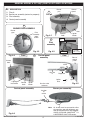
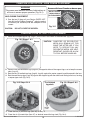
MANUAL MODEL # OC-34(P) PARTS LIST AND LOCATIONS
NO.
1.
2.
3.
4.
DESCRIPTION
Fire pit
Burner pan assembly (natural or propane)
Pilot assembly
Control panel assembly
Burner
pan
1
Control
panel
Fire pit
2
BURNER PAN ASSEMBLY
Burner
pipe
Vent
Pilot
assembly
under
screen
Control
knob
Fig. 4-1
Burner
pan
3
Ignitor
button
Thermocouple
Pilot
assembly
Burner
pan
Fig. 4-3
Fig. 4-2
Fig. 4-4
Front
4
Pilot
assembly
(under screen)
Burner pipe
Rear
Control panel
assembly
Rear of
control
panel
Access
door
Valve
Gas line
in
Lighting
instructions
Ignitor
wire
Control
knob
Ignitor
button
Control panel assembly
Ignitor
Fig. 4-5
Gas line valve
to burner
Burner pan assembly
Location
of
orifice
Note:
Fig. 4-6
REV 10 - 0710110811
Regulator
4
Air shutter must be removed & orifice
changed for use with different gas.
See the CONVERTING THE MANUAL
VALVE OUTDOOR CAMPFYRE™ TO
A DIFFERENT GAS TYPE section.
L-A2-18207
REMOTE MODEL # OC-34-01(P) PARTS LIST AND LOCATIONS
NO. DESCRIPTION
1.
2.
3.
4.
5.
Burner pan
Control panel
access door
Fig. 5-1
Fire pit
Burner pan assembly (natural or propane)
Pilot assembly
Control panel assembly
Remote handset
Vent
Remote
receiver &
switch
Fire pit
1
Fig. 5-3
Burner assembly
2
Burner
ring
Pilot
assembly
under
screen
Burner
pan from
below
Burner
pan
Burner
pipe
Gas
line in
Fig. 5-2
3
Pilot assembly
(under screen)
Burner
pan
Control panel assembly
(door removed for photo)
4
5
Remote
handset
Control
buttons
Pilot
hood
Flame
sensor
and
electrode
Ignitor
electrode
Burner pipe
Pilot
assembly
Front
Fig. 5-4
Rear
Fig. 5-5
Control
valve
Fig. 5-6
Valve magnet wire
(black)
(do not remove)
Orange (THTP)
Remote valve
Wire harness
Green (TH)
Black (TP)
Remote
switch
I
(Brown- 2 wires)
to remote switch
S
S
To pilot assembly
probes
I
Sensor
Ignitor
Ignitor pack
(Black) to
Battery
holder
Wiring diagram for remote valve
Outdoor Campfyre™
2x D cells
(Red) to
battery holder)
Fig. 5-1
Rear of control panel
REV 10 - 0710110811
Y
5
L-A2-18207
IMPORTANT SAFETY INFORMATION
PRE-INSTALLATION AND OUTDOOR CAMPFYRE™ PREPARATION SAFETY GUIDELINES
A. Before installing this Outdoor Campfyre™, check MINIMUM CLEARANCE TO COMBUSTIBLES (p. 10) to
ensure that the surrounding area is properly sized for the installation. MINIMUM CLEARANCES must
be maintained when you install this Outdoor Campfyre™. ALL SIDES of the enclosure opening MUST
BE AT LEAST 36" from any combustible side walls. The unit MUST NOT BE installed under any type of
ceiling or overhang.
B. The Outdoor Campfyre™ is for outdoor use only. DO NOT install or use this appliance inside a building,
garage, or any other enclosed area, including recreational vehicles and/or boats. This unit must be
installed in such a manner that the vent openings at the base of the unit remain clear and free of
all obstructions at all times and during all weather conditions.
C. CHECK GAS TYPE (natural gas or propane): The gas supply you intend to use may not be the same as
that stated on the Outdoor Campfyre™ rating plate as purchased. If the gas supply is different, convert
the Outdoor Campfyre™ to the gas type you intend to use. See instructions on p. 25. If you are unsure,
contact the dealer for assistance.
D. FOR NATURAL GAS: The minimum inlet gas-supply pressure for purposes of input adjustment is 5" water
column (w.c.), and the maximum inlet gas-supply pressure is 10.5 " w.c. FOR PROPANE: The minimum
inlet gas-supply pressure for purposes of input adjustment is 8" w.c., and the maximum inlet gas-supply
pressure is 13" w.c. DO NOT INSTALL THIS UNIT IF MINIMUM PRESSURE IS NOT AVAILABLE OR
IF MAXIMUM PRESSURE IS EXCEEDED.
E. Gas piping system must be sized to provide minimum inlet pressure at the maximum flow rate (BTU/hr).
Undue pressure loss will occur if the pipe is too small, or the run is too long.
F. For installations at elevations above 2,000 ft., contact your local dealer or gas supplier before installing.
Input ratings should be reduced approximately 4% for each 1,000 ft. above sea level. Refer to the National
Fuel Gas Code.
G. The Outdoor Campfyre™ and its main gas valve must be disconnected from the gas-supply piping system
during any pressure testing of that system at test pressures in excess of 1/2 psig. This is accomplished by
closing the gas-supply line valve. The Outdoor Campfyre™ must be isolated from the gas-supply piping
system by closing its equipment shutoff valve during any pressure testing of the gas-supply piping system
at test pressures equal to or less than 1/2 psig.
H. INSTALLER NOTE: This unit should be installed so that it can be removed if service is required. Any
protrusion into the Outdoor Campfyre™ enclosure may obstruct the frame and prevent the unit from being
removed (see GAS-SUPPLY PLUMBING REQUIREMENTS below).
I. GAS-SUPPLY PLUMBING REQUIREMENTS
Apply only joint compounds that are resistant to all gasses on all male pipe fittings. Make sure to tighten
every joint securely. Do not use pipe joint compound to connect flare fittings. Bring the gas-supply pipe
up from beneath the enclosure near its center. If it is not possible to stub the gas line in from the center
of the enclosure, the connection may be made through the side of the enclosure.
Note: An external on/off valve in the gas line is required for safety when the Outdoor Campfyre™ is
not in use. It also provides for convenient maintenance and repair.
REV 10 - 0710110811
6
L-A2-18207
IMPORTANT SAFETY INFORMATION (Cont.)
CAUTION:
Installation and maintenance must be done by an NFI Certified or other qualified professional
installer.Installer, read these instructions before installing this product.
Be sure you understand all safety precautions and warnings contained in this manual.
INSTALLATION SAFETY GUIDELINES
A. Carefully inspect the burner and log cartons for shipping damage. If any parts are damaged, call the
dealer.
B. Correct installation and proper placement of the burner assembly, Lava Chunks, and other decorative
options are crucial to the safe performance of the Outdoor Campfyre™. See installation instructions
(pages 13-18) for further information. NEVER COVER THE BURNER SCREEN WITH LAVA CHUNKS,
LOGS, OR ANY OTHER ITEM. THIS WILL IMPAIR ITS EFFICIENCY AND CAUSE THE UNIT TO
MALFUNCTION.
C. Ensure that the unit is installed in such a manner that the vent openings at the base of the unit remain
obstacle-free at all times and during all weather conditions (see Fig. 16-2).
D. Due to high temperatures, the Outdoor Campfyre™ must be located out of traffic areas and away from
combustibles.
OPERATING THE OUTDOOR CAMPFYRE™ SAFELY AND CORRECTLY
A. When shutting the unit down—be sure to TURN THE CONTROL VALVE FULLY OFF.
B. Children MUST be carefully supervised when in the vicinity of this appliance.
C. DO NOT sit or place any part of the body or combustible materials on or near the Outdoor Campfyre™
surround or gas log set. Children and adults should be alerted to the hazard of high surface temperatures
and should stay away to avoid burns or clothing ignition.
D. Every time you use the Outdoor Campfyre™, make sure that:
1. The area around the Outdoor Campfyre™ is clear of flammable substances such as gasoline, yard
debris, wood, etc.
2. THE SCREEN IS NOT COVERED OR BLOCKED WITH LAVA CHUNKS OR ANY OTHER ITEM (see
the LAVA CHUNK AND LOG PLACEMENT section and Fig. 15-1.)
3. There is no blockage of the airflow through the vent openings (see Fig. 23-1 on p. 23) located on the
lower side walls of the unit.
E. WARNING: HOT WHILE IN OPERATION AND FOLLOWING OPERATION. Children must be carefully
supervised when in the vicinity of this appliance. Serious injury can occur! DO NOT throw trash, paper, or
other flammable materials onto the Outdoor Campfyre™. DO NOT leave in operation when unattended.
WARNING: DO NOT operate this Outdoor Campfyre™ in the rain.
F. SOLID FUEL MUST NOT BE BURNED in the Outdoor Campfyre™.
G. DO NOT continue using if you smell unusual odors, or have headaches, nausea, or dizziness.
H. DO NOT store any combustible materials, gasoline, and any other flammable vapors/liquids in the vicinity
of the Outdoor Campfyre™. Provide adequate clearance for servicing and operation.
I. DO NOT place clothing or any flammable material on or near the Outdoor Campfyre™. Matches, paper,
garbage, or any other material must not be thrown on top of the logs, burner, or into the flame.
J. DO NOT use the Outdoor Campfyre™ if any part of it has been underwater. Immediately call a qualified
professional service technician to inspect the set and to replace any part of the control system that has
been underwater.
REV 10 - 0710110811
7
L-A2-18207
UTILISATION SÛRE ET ENTRETIEN DES CYLINDRES DE GAZ DE PROPANE
IMPORTANT POUR VOTRE SÛRETÉ
LISEZ ET SUIVEZ TOUS LES AVERTISSEMENTS ÉQUIPÉS DE VOTRE CYLINDRE DE GAZ DE PROPANE.
En actionnant cet appareil avec un cylindre de gaz de propane ON DOIT observer ces instructions et avertissements.
LE MANQUE DE FAIRE AINSI PEUT AVOIR COMME CONSÉQUENCE UNE INCENDIE OU UNE EXPLOSION SÉRIEUSE.
CYLINDRE ET CONDITIONS ET
CARACTÉRISTIQUES DE CONNECTEUR
déceler les fuites. Arrêtez les valves de unité
et ouvrez la valve principale de cylindre, puis
vérifiez les raccordements avec de l’eau
savonneux. Réparez toutes les fuites avant
d’allumer le unité.
a. Des cylindres et les valves de gaz de propane doivent
être maintenus en bon état et doivent être remplacés s’il
y a des dommages évidents au cylindre ou à la valve.
ATTENTION: Tournez toujours la valve principale de cylindre
b. Ce unité, une fois utilisé avec un cylindre, devrait être
de propane au loin après chaque utilisation,
relié à un gallon de la norme 5 (20 lb.) cylindre de gaz
et avant de déplacer le unité et le cylindre, ou
débrancher l’accouplement. Cette valve doit
de propane équipé d’un OPD (remplissez au-dessus du
rester fermée et le cylindre a débranché alors
niveau le dispositif d’empêchement). L’OPD a été exigé
que l’appareil n’est pas en service, quoique
sur tous les cylindres vendus depuis octobre 1.1998 pour
l’écoulement de gaz soit arrêté par un dispositif
empêcher le remplissage excessif.
de sûreté quand le coupleur est débranché.
c. L e s d i m e n s i o n s d e c y l i n d r e d ev r a i e n t ê t r e
Inspectez soigneusement l’ensemble de tuyau chaque fois
approximativement 12" (30.5cm.) de diamètre et 18"
avant que le gaz soit allumé. Un tuyau criqué ou frangé devrait
(45.7cm.) hauts. Des cylindres doivent être construits et
être remplacé immédiatement.
marqués selon les caractéristiques pour des cylindres
de gaz de propane du département des ETATS-UNIS du Si l’appareil est stocké à l’intérieur, le cylindre doit être débranché
transport (D.O.T.) ou le niveau national du Canada, du et enlevé. Des cylindres doivent être stockés hors des portes, hors
CAN/CSA-B339, des cylindres, des sphères et des tubes de l’extension des enfants, et ne doivent pas être stockés dans un
bâtiment, le garage, ou n’importe quel autre secteur inclus.
pour le transport des marchandises dangereuses.
d. Le cylindre doit inclure un collier pour protéger la valve POUR VOTRE SÛRETÉ
de cylindre et le circuit d’alimentation de cylindre doit a. Ne stockez pas un cylindre de gaz disponible de propane
être assuré le retrait de vapeur.
dessous ou ne vous approchez pas de cet appareil.
e. Le régulateur de pression et l’ensemble de tuyau (Fig. b. Ne remplissez jamais cylindre au delà de 80 pour cent de
plein.
8-1) fourni avec cet appareil à cuire extérieur de gaz
doivent être utilisés. Les régulateurs d’original et de pression c. SI L’INFORMATION DANS “A” ET “B” N’EST PAS SUIVIE
de remplacement et les ensembles de tuyau doivent
EXACTEMENT, UN FEU CAUSANT LA MORT OU DES
être ceux indiqués par le Robert H. Peterson Cie. pour
DOMMAGES SÉRIEUX PEUT SE PRODUIRE.
le raccordement avec un dispositif se reliant de cylindre POUR VOTRE SÛRETÉ, vous devez fournir les ouvertures
identifié comme type I par la norme ANSI Z 21.58 et suivantes ci-dessous pour le drainage, l’air de rechange, et
CGA 1.6-M95-1995 avec la norme ANSI Z 21.58a -1998 la ventilation en travers de n’importe quelle zone de stockage
d’addenda et CGA 1.6a - M98.
exposée à la fuite possible des raccordements de gaz, du unité,
f. La valve de cylindre de gaz de propane doit être équipée ou du cylindre de propane:
d’un dispositif d’accouplement de raccordement de Un côté de la clôture de cylindre de gaz a laissé complètement
cylindre, décrit comme type I dans la norme définie ouvert de extérieur OU en fournissant quatre (4) ouvertures de
dans le e. de paragraphe ci-dessus. Ce dispositif est ventilation. Deux ouvertures doivent être au niveau de valve de
généralement décrit comme coupleur rapide de fil de cylindre (approximativement 16" (40.6 centimètres) au-dessus du
point culminant.
plancher) et sur les murs opposés de la clôture. Deux ouvertures
g. Si votre cylindre de gaz de propane vient avec une prise supplémentaires doivent être au niveau de plancher des côtés
de la poussière, placez le bouchon anti-poussière sur la opposés de la clôture. Les ouvertures de niveau de plancher
sortie de valve de cylindre toutes les fois que le cylindre doivent commencer au plancher et se prolongeront pas plus
n’est pas en service.
haut que 5"(12.7 centimètre) au-dessus du plancher. Chaque
ouverture doit avoir un minimum de 10 pouces carrés (64.5 cm2)
OPÉRATION DE COUPLEUR RAPIDE
du secteur libre. Pour réaliser la ventilation appropriée, vous
Pour relier le regulator/hose à l’ajustage de précision de
pouvez forer une série de trous, omettez le coulis des joints de
valve de cylindre de gaz de propane: Serrez l’écrou de main
maçonnerie, ou remplacez une brique avec un écran de tissu de
sur le régulateur au-dessus de l’ajustage de précision de fil
matériel. Si le plancher dans le coffret est augmenté et l’espace
de point culminant sur la valve de cylindre. Tournez l’écrou de
sous le coffret est ouvert d’extérieur, les ouvertures inférieures
main dans le sens des aiguilles d’une montre pour engager les
de ventilation peuvent être dans le plancher.
fils et pour serrer jusqu’à ce que douillettement. L’utilisation des
Fig. 8-1 type coupleur rapide de fil de point culminant d’I
pinces ou de la clé ne devrait pas être nécessaire. Seulement
Volant de commande
le propane marqué par cylindres doit être employé.
Ajustage de précision
en laiton de fil de
Régulateur
QCC
Pour débrancher: Tournez l’écrou de main dans le sens Type 1
point culminant
contraire des aiguilles d’une montre jusqu’à isolé (fig. Valve
UL
8-1).
Valve
Important:
de
décompression
Avant d’employer le unité, et ensuite chaque
fois que le cylindre est enlevé et rattaché,
examinez tous les raccordements pour
REV 10 - 0710110811
8
Indicateur
de niveau
de liquide
(facultatif)
Écrou de main avec le
fil de point culminant.
Passage
Tuyau
L-A2-18207
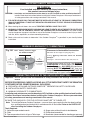
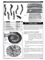
SAFE USE & MAINTENANCE OF PROPANE-GAS CYLINDERS
IMPORTANT FOR YOUR SAFETY
READ AND FOLLOW ALL WARNINGS PROVIDED WITH THE PROPANE-GAS CYLINDER.
When operating this appliance with a propane-gas cylinder, these instructions and warnings MUST be observed.
FAILURE TO DO SO MAY RESULT IN A SERIOUS FIRE OR EXPLOSION.
Important: Before using the unit, and after each time
CYLINDER/CONNECTOR REQUIREMENTS
the cylinder is removed and reattached,
a. Propane-gas cylinders, valves, and hoses must be
check the hose for wear (see a.) and check
maintained in good condition and must be replaced if
all connections for leaks. Turn off the unit
valves and open the main cylinder valve,
there is visible damage to either the cylinder or valve. If the
then check connections with soapy water.
hose is cut or shows excessive abrasion or wear, it must
Repair any leaks before lighting the unit.
be replaced before using the gas appliance (see e.).
Always turn the propane cylinder main
b. This unit, when used with a cylinder, should be connected CAUTION:
valve off after each use, and before moving
to a standard 5-gallon (20 lb.) propane-gas cylinder
the unit and cylinder, or disconnecting the
equipped with an OPD (Overfill Prevention Device).
coupling. This valve must remain closed
The OPD has been required on all cylinders sold since
and the cylinder disconnected while the
October 1,1998, to prevent overfilling.
appliance is not in use, even though the gas
flow is stopped by a safety feature when the
c. Cylinder dimensions should be approximately 12" (30.5
coupler is disconnected.
cm.) in diameter and 18" (45.7 cm.) high. Cylinders
must be constructed and marked in accordance with Carefully inspect the hose assembly each time before the
the Specifications for Propane Gas Cylinders of the U.S. gas is turned on. A cracked or frayed hose should be replaced
Department of Transportation (D.O.T.) or the National immediately.
Standard of Canada, CAN/CSA-B339, Cylinders,
If the appliance is stored indoors, the cylinder must be
Spheres, and Tubes for Transportation of Dangerous
disconnected and removed. Cylinders must be stored out
Goods.
of doors, out of the reach of children, and must not be
d. The cylinder must include a collar to protect the cylinder stored in a building, garage, or any other enclosed area.
valve, and the cylinder supply system must be arranged
FOR YOUR SAFETY
for vapor withdrawal.
e. The pressure regulator and hose assembly used must a. DO NOT store a spare propane-gas cylinder under or
near this appliance.
match the specification for Type I by ANSI Z 21.58b.
NEVER
fill the cylinder beyond 80-percent full.
2005/CGA 1.6-2005 (see Fig. 9-1). This unit is not
equipped with a propane regulator but if it is set up for c. IF THE INFORMATION IN a. AND b. IS NOT FOLLOWED
use with propane gas, then the regulator must meet the
EXACTLY, A FIRE CAUSING DEATH OR SERIOUS
INJURY MAY OCCUR.
above specification. Contact your local dealer for more
information.
f.
The propane-gas cylinder valve must be equipped with a
cylinder connection coupling device, described as Type
I in the standard defined in paragraph e. above. This
device is commonly described as an Acme thread quick
coupler.
g. If the propane-gas cylinder comes with a dust plug, place
the dust cap on the cylinder valve outlet whenever the
cylinder is not in use.
QUICK COUPLER OPERATION
To connect the regulator/hose assembly to the propanegas cylinder valve fitting: Press the hand nut on the regulator
over the Acme thread fitting on the cylinder valve. Turn the
hand nut clockwise to engage the threads and tighten until
snug. The use of pliers or a wrench should not be necessary.
Only cylinders marked "propane" may be used.
To disconnect: Turn the hand nut counterclockwise until
detached (Fig. 9-1).
Fig. 9-1 Type I Acme thread quick coupler
QCC
Type 1
valve
Pressure
relief
valve
Hand wheel
Brass Acme
thread fitting
Regulator
UL
Liquid level
indicator
(optional)
Hand nut with Acme
thread
Vent
Hose
Consult your gas supplier for ventilation and regulator requirements when connecting to a household propane supply.
REV 10 - 0710110811
9
L-A2-18207
IMPORTANT SAFETY INFORMATION
BE CAREFUL
If not installed and used correctly per these instructions,
this product can cause serious injury.
CAUTION:
Installation and maintenance must be done by an NFI Certified or other qualified professional
installer. Read these instructions before installing this Outdoor Campfyre™. Be sure you understand
all safety precautions and warnings contained in this manual.
A. FOR OUTDOOR USE ONLY. THIS UNIT MUST BE INSTALLED AT LEAST 36" FROM ANY COMBUSTIBLE
WALLS OR MATERIAL. IT MUST NOT BE INSTALLED UNDER ANY TYPE OF CEILING OR OVERHANG
(SEE FIG. 10-1).
B. When shutting the unit down—be sure to TURN THE CONTROL VALVE FULLY OFF.
C. WARNING: CARBON MONOXIDE POISONING MAY LEAD TO DEATH. DO NOT MODIFY THIS OUTDOOR
CAMPFYRE™ OR ITS CONTROLS, EXCEPT AS PROVIDED FOR IN THIS MANUAL. Any other change
may be dangerous. Improper installation or use of the Outdoor Campfyre™ can cause serious injury or death
from fire, burns, explosions, or carbon monoxide poisoning.
D. Check state and local codes to determine if the Outdoor Campfyre™ is permitted in your locality before
installation.
MINIMUM CLEARANCE TO COMBUSTIBLES
Fig. 10-1
Clearances to Combustible Construction:
NOTE:
Note: NOTHING
Nothing
should be
SHOULD
BEabove
ABOVE
THE
OUTDOOR
the Outdoor
Campfyre™.
Side walls: 36" from edge of top ring (Fig. 10-1).
CAMPFYRE.
Ceiling: Nothing should be above the Outdoor
Campfyre™.
36"
36
CLEARANCE
Clearance
36"
36
CLEARANCE
Clearance
FROM
SIDES
From sides
to
ANY
anyTO
combustible
COMBUSTIBLE
construction
CONSTRUCTION
FROM
SIDES
From sides
to
TO ANY
any combustible
COMBUSTIBLE
CONSTRUCTION
construction
Flooring: 0" - Can be installed on deck, slab, floor, etc.
The dimensions shown in Fig. 10-1 are MINIMUM
CLEARANCES to maintain when you install this
Outdoor Campfyre™. ALL SIDES of the enclosure
opening MUST BE AT LEAST 36" from any
combustible side walls. The unit MUST NOT BE
installed under any type of ceiling or overhang.
CONNECTING THE GAS TO THE OUTDOOR CAMPFYRE™
Important: Be sure you have read and understand all safety precautions and warnings contained in this
manual.
BEFORE PROCEEDING, CAREFULLY READ ALL OF THE IMPORTANT SAFETY INFORMATION
CONTAINED IN THIS OWNER’S MANUAL, INCLUDING:
A. PRE-INSTALLATION AND OUTDOOR CAMPFYRE™ PREPARATION SAFETY GUIDELINES.
B. INSTALLATION SAFETY GUIDELINES.
C. MINIMUM CLEARANCE TO COMBUSTIBLES.
Installation and maintenance must be done by an NFI Certified or other qualified professional installer.
Installer: Read these instructions before installing this Outdoor Campfyre™. Be sure you understand
all safety precautions and warnings contained in this manual.
BE SURE THE GAS SUPPLY FOR THE OUTDOOR CAMPFYRE™ IS TURNED OFF.
Note: To install the Peterson Outdoor Campfyre™, you must have a gas-supply line that has been installed
by a qualified professional technician in accordance with all local codes. Refer to the PARTS LIST
when installing the Outdoor Campfyre™.
Tools Required:
4. Soapy water solution & brush for leak detection
1. Adjustable open-ended wrench
5. Phillips-head screwdriver
2. Pliers
6. Manometer (recommended for checking gas pressure)
3. Pipe compound resistant to all gas or Teflon tape
REV 10 - 0710110811
10
L-A2-18207
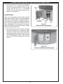
CONNECTING THE GAS TO THE OUTDOOR CAMPFYRE™ (Cont.)
Place the Outdoor Campfyre ™ enclosure at the installation location over the gas-supply
pipe. The supply pipe should not protrude more than 3" up into the enclosure. Ensure the
flex connector does not become kinked or damaged. Do not allow the unit to rest on it.
If using propane gas, it is recommended that the supply tank be set a minimum of 10' from the
Outdoor Campfyre™. Use black steel pipe for the supply pipe, with a shutoff valve in line before the
Outdoor Campfyre™.
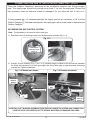
ACCESSING THE GAS CONTROL SYSTEM
Note: The procedure is the same for either valve type.
1. Remove the four (4) retaining screws from the burner pan assembly (Fig. 11-1).
Fig. 11-1
Burner pan
retaining screw
holes (4)
2. Carefully lift pan assembly (Fig. 11-2 or 11-3), allowing access to center of fire pit and flex connector
kit. Attach flex connector kit to main gas-supply line using Teflon tape or pipe compound resistant to
propane gas. Tighten connections.
Fig. 11-2 Manual unit shown
Fig.11-3 Remote unit shown
Figure 4.
LineFROM
from
LINE
valve to
VALVE
TO
burner
BURNER
Burner
pan
PilotGAS
gas line
PILOT
LINE
Pilot gas line
GAS
LINE
Gas line
IN
in
Line from
valve to
burner
CAREFULLY LIFT BURNER ASSEMBLY FROM THE ENCLOSURE TO ACCESS GAS CONNECTION
POINT AT VALVE. BE CAREFUL NOT TO DETACH ANY WIRES OR DAMAGE GAS LINES.
REV 10 - 0710110811
11
L-A2-18207
CONNECTING THE GAS TO THE OUTDOOR CAMPFYRE™
3. Make sure that the control knob on the manual
unit (see Fig. 12-1), or the manual ON/OFF
switch and remote ON/OFF switch on the
remote unit (see Fig. 12-2), is in the OFF
position. Turn on the main gas supply. Test for
leaks at all connections.
Access
door
LEAK TESTING
Never use an open flame to test for leaks. Instead,
apply soapy solution (equal parts liquid detergent
and water) at all connections. If bubbles appear, a
leak is present. Turn off gas and tighten connection;
turn on gas and repeat leak test. Repeat until no
leaks are detected. If a leak persists, turn off gas
supply and contact the local gas company or dealer
where you purchased the unit.
Lighting
instructions
Control
knob
Ignitor
button
Fig. 12-1
Manual unit control panel
4. When complete (no leaks are found), re-center
the burner assembly in the enclosure. Make
certain that no part of the assembly protrudes
beyond the face of the enclosure, no wires have
come disconnected or loose, and the burner
pan sits level. Replace and tighten the retaining
screws.
Fig. 12-2
Front of remote unit control panel
REV 10 - 0710110811
12
L-A2-18207
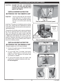
INSTALLING/REPLACING BATTERIES
CAUTION: ENSURE THE UNIT IS CONNECTED
TO THE GAS LINE AND HAS BEEN
TESTED FOR LEAKS BEFORE YOU
INSERT BATTERIES.
INSTALLING/REPLACING THE
BATTERIES FOR THE REMOTE UNIT
Important:
You may access the rear of the control
panel where the "D" battery pack is
located by removing the door and then
the four (4) control panel securing
screws.
Retaining screws
Fig. 13-1
Front of remote unit control panel
Install two "D" batteries in the battery pack as shown
in Fig. 13-2, taking care not to disconnect or loosen
wiring. Reassemble control panel into the enclosure,
replacing the door.
Remote
receiver
(rear)
To access the "AA" battery pack, unscrew and remove
the two (2) retaining screws on the control system
(Fig. 13-3). Remove the control system and then
slide open the battery pack lid as shown in Fig. 134. Replace the old batteries with four (4) new "AA"
batteries. Resecure the battery pack lid and return
the control system into the control panel. Screw in
the two (2) retaining screws.
Battery pack
(2 D-cells)
Fig. 13-2
Rear of remote unit control panel
Fig. 13-3
Unscrew control system
INSTALLING/REPLACING THE
BATTERIES FOR THE MANUAL UNIT
The ignitor requires one "AA" battery (included).
1. Unscrew the plastic cover of the ignitor button
and remove (Fig. 13-5).
2. Lift out spring and, if installed, the battery
together, noting position of positive end of
battery (Fig. 13-6). Remove and replace with
new battery as needed.
Fig. 13-4
Battery pack exposed
3. Fit spring and battery back into recess and
replace cap, screwing it clockwise until snug.
Do not overtighten.
Fig. 13-5
REV 10 - 0710110811
13
Fig. 13-6
L-A2-18207
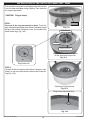
INSTALLATION OF THE OUTDOOR CAMPFYRE™ RING
First, remove the ring from its packaging and make sure that
it has not been damaged during shipping. Then follow the
two simple steps below.
CAUTION: Ring is heavy.
Fire Ring
Fire
ring
STEP 1:
You must fix the ring permanently in place. To do this,
apply a bead of high-temperature silicone (included) around
the top of the Outdoor Campfyre™ base, just outside of the
raised locator tags (Fig. 14-2).
Fig. 14-1
RING
TABS
RingLOCATOR
locator tabs
Silicone bead
Silicone
bead
Appy silicone
silicone within
Apply
withinthis
thisarea
area
outside ring locator tabs
Apply a bead of silicone as shown
on the area where ring will sit.
Fig. 14-2
Ring locator tab
STEP 2:
Carefully lift the fire ring over the Outdoor Campfyre™ and
place it on top of the base with the locator tabs inside the
ring (Fig. 14-4).
Carefully set ring into place
Fig. 14-3
Ring locator tabs inside ring.
Fig. 14-4
REV 10 - 0710110811
14
L-A2-18207
PARTS LISTS AND SETUP INSTRUCTIONS
OUTDOOR CAMPFYRE™ DECORATIVE OPTIONS
The OC-34 Outdoor Campfyre™ has several decorative options, each with a different set of components and
setup instructions. Find the section that pertains to your model and follow those setup instructions, then proceed
to the OPERATING THIS OUTDOOR CAMPFYRE™ section to test your installation.
Note: Lava Chunks are always placed on the burner first in each option. This provides a base for the
diffusion of gas and air.
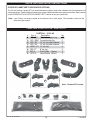
CAMPFIRE LOGS OPTION - PARTS LIST
#
1.
2.
3.
4.
5.
6.
7.
8.
CARTON 1: (OCL-34)
Part #
Description
OCL-8YC “Y” center support log
OCL-15BC Curved bottom log
OCL-12T 12" top log with knothole
OCL-13T 13" top log with knothole
HRDL-12T 12" top log
RDL-7T
8" top log
WC-6
Wood chips (6 pcs.)
OCC-8
Lava Chunks (8 lbs.)
4
3
5
Qty
1
2
1
1
2
4
1
2
1
5
2
2
6
Note: Photos NOT to scale.
7
8
8
REV 10 - 0710110811
15
L-A2-18207
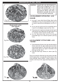
CAMPFIRE LOGS OPTION - LAVA CHUNK PLACEMENT
WARNING
This screen must be clear and free of obstructions at
all times to ensure proper operation (Fig. 16-1).
Screen with Lava Chunks on burner pan
DO NOT PLACE
LAVA CHUNKS
ON THE SCREEN
LAVA CHUNK PLACEMENT
1. Pour the two (2) bags of Lava Chunks (PARTS LIST,
Item #8) into the Outdoor Campfyre™, evenly covering
the burner pan assembly with the exception of the
screen.
CAUTION:
Fig. 16-1
DO NOT COVER THE SCREEN.
CAMPFIRE LOGS OPTION - LOG PLACEMENT
1. Place the Y-shaped support log (Log #1) on the lava in the center of the enclosure (Fig.16-2).
Fig. 16-2 Steps 1 & 2
Screen
CAUTION:
2
1
CAMPFIRE OR DECORATIVE
MEDIA WILL REMAIN HOT FOR
SOME TIME AFTER USE. IF YOU
NEED TO REPOSITION ANY
DECORATIVE MEDIA, USE HEATRESISTANT GLOVES OR ALLOW
TO COOL BEFORE HANDLING.
2
2. Place the two curved bottom logs (Logs #2) on opposite sides of the support log so as to keep the screen
clear (Log #1).
3. Rest the two (2) knothole top logs (Log #3, Log #4) against the center support log with one end in the lava.
4. Rest the next two top logs (Logs #5) against the support log with the other ends resting in the lava, forming
a teepee-type stack (Fig. 16-3).
The finished
log stack
Fig. 16-3 Steps 3 & 4
Fig. 16-4 Steps 5 & 6
4
3
5
Control
panel
5. Place the four (4) smallest logs (Item #6) so they rest on the curved bottom logs as desired.
6. Place the six (6) wood chips (Item #7) as desired around the log stack (Fig. 16-4).
REV 10 - 0710110811
16
L-A2-18207
BEACHWOOD LOGS AND/OR VOLCANIC STONE OPTION - PARTS LIST
8
2
4
8
3
1
Fig. 17-1
5
#
1.
2.
3.
4.
5.
6.
7.
8.
9.
6
Description
Knotted log
Hooked log
Crooked log
Curved log
Stripped log
Long charred log
Short charred log
Lava Chunks (8-lb. bag)
Volcanic Stones (box)
9
7
Part Number
OCBWL-17
OCBWL-18
OCBWL-16
OCBWL-15
OCBWL-12
OCBWL-20
OCBWL-9
OCC-8
VS-25
Qty
1
1
1
1
1
1
1
2
1
BEACHWOOD/VOLCANIC STONE
OPTION - SETUP
Although log placement may vary, suggested log
®
placement for the Beachwood log set is provided
below. These log placements will allow for superior flame
pattern and appearance. Please read these instructions
completely and carefully before beginning.
CHUNK AND STONE PLACEMENT
WARNING: Use only parts specifically approved
for use with this Real Fyre® outdoor
campfire. Failure to do so may result
in proper ty damage or personal
injury. Check with your local Real
Fyre ® dealer if you need more
information.
Keep
screen
clear
1. Empty both bags of Lava Chunks into the burner
pan (Parts List, Item #8) and even it out without
covering or blocking the ignitor screen (see Fig.
17-2).
Fig. 17-2
2. Pour the Volcanic Stones on top to fill the whole
burner pan.
With the ignitor screen clear of Lava Chunks and
Volcanic Stones distributed on top of the Lava
Chunks, nearly any log placement is possible. It is
also possible to use only the Volcanic Stones and
no logs at all.
2
1
Some general guidelines include always placing the
flat side of each log downward or inward and making
sure the logs are positioned so they are stable and
will not shift or roll. Logs must remain in the burner
Fig. 17-3
REV 10 - 0710110811
17
L-A2-18207
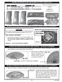
BEACHWOOD OPTION - SETUP
CAUTION:
6
3
4
5
CAMPFIRE OR DECORATIVE
MEDIA WILL REMAIN HOT FOR
SOME TIME AFTER USE. IF YOU
NEED TO REPOSITION ANY
DECORATIVE MEDIA, USE HEATRESISTANT GLOVES OR ALLOW
TO COOL BEFORE HANDLING.
LOG PLACEMENT OPTION TWO - LOG
SQUARE
7
1. Lay Log #1 across the Volcanic Stone, then lay the
hooked part of Log # 2 over one end of Log #1 at
an angle of approximately 90 degrees (see Fig. 163).
Fig. 18-1
Beachwood Log Set
Other options
2. Lay an end of Log #3 over the unattached end of
Log #2 at a 90-degree angle (see Fig. 18-2).
3. Place one end of Log #4 over the open end of Log #3
and the other end underneath the open end of Log
#1, creating a kind of square (see Fig. 18-2).
3
2
4
4. Lay the remaining logs across the already
positioned logs in an attractive pattern (see Fig.
18-3).
1
LOG PLACEMENT OPTION THREE - LOG
"TEEPEE"
Fig. 18-2
1. Place the ends of three or four logs into the Volcanic
Stones with their flat sides facing inward and their
tops pointed upward. Then lean their other ends
against each other at an angle in the center of the
fire ring (see Fig. 18-4).
5
6
7
2. Place the other logs similarly as shown (see Fig.
18-5).
Enjoy your campfire. After the logs are placed, consider
how changing their arrangement could produce even
more pleasing flame patterns. Always observe the
caution at the top of this page and the guidelines on
p. 1.
Fig. 18-3
7
1
5
4
2
3
6
Fig. 18-5
Fig. 18-4
REV 10 - 0710110811
18
L-A2-18207
GLASS OR RIVER ROCK ON GLASS OPTION - PARTS LIST
Item#
1.
2.
3.
Description
Glass (10-lb. bag)
Lava Chunks (8-lb. bag)
Box of river rock (optional)
Part Number
OCGL-x
OCC-8
STN-10
Qty
3
2
1 or 2 as desired
Replace “x” in model number with the
glass code in parentheses below:
Black (B)
Clear (C)
Bronze (Z)
Sapphire blue (S)
Emerald green (E)
2
1
1
1
3
2
GLASS OR RIVER ROCK ON GLASS OPTION - LAVA CHUNK PLACEMENT
WARNING
Screen with Lava Chunks on burner pan
This screen must be clear and free of obstructions at
all times to ensure proper operation (Fig. 19-1).
DO NOT PLACE
LAVA CHUNKS
ON THE SCREEN
LAVA CHUNK PLACEMENT
1. Pour the two (2) bags of Lava Chunks (PARTS LIST,
Item #2) into the Outdoor Campfyre™, evenly covering
the burner pan assembly with the exception of the
screen.
CAUTION:
Fig. 19-1
DO NOT COVER THE SCREEN.
GLASS OR RIVER ROCK ON GLASS OPTION - GLASS PLACEMENT
1. Pour the glass out of the bags onto the installed Outdoor Campfyre™, evenly covering the Lava Chunks
(see above) but not the screen (Fig. 19-2 and 19-3).
Fig. 19-2
2. Add stones as indicated
below or other decorative
options certified for use
with this burner. (Contact
your dealer for details.)
Fig. 19-3
CAUTION: DO NOT COVER THE SCREEN.
GLASS OR RIVER ROCK ON GLASS OPTION - RIVER STONE PLACEMENT
1. Place river stones in a decorative pattern on top of glass but not covering the screen.
CAUTION:
Fig. 19-4
REV 10 - 0710110811
19
CAMPFIRE OR DECORATIVE MEDIA WILL
REMAIN HOT FOR SOME TIME AFTER
USE. IF YOU NEED TO REPOSITION
ANY DECORATIVE MEDIA, USE HEATRESISTANT GLOVES OR ALLOW TO
COOL BEFORE HANDLING.
L-A2-18207
OPÉRER VOTRE CAMPFYRE DE PLEIN AIR - ALLUMER & ÉTEINDRE.
Nous recommandons qu’avant que vous installiez votre Campfyre De plein air, vous vous familiarisez avec la disposition de la valve
du contrôle.
Pour votre sécurité lisez avant d’allumer
Avertissement. Quiconque ne respecte pas a la lettre les instructions dans la présente notice risque
de déclencher un incendie ou une explosion entraînant des dommages, des blessures ou la mort.
Avant d’allumer la veilleuse, reniflez tout autour de l’appareil pour déceler une odeur de gaz. Reniflez près
du plancher, car certains gaz sont plus lourds que l’air et peuvent s’accumuler au niveau du sol. SI VOUS
SENTEZ DU GAZ SUIVRE LES DIRECTIVES SUR P. 1.
Ne poussez ou tournez la manette d’admission du gaz qu’à la main; ne jamais utiliser d’outil. Si la manette
reste coincée, ne tentez pas de la réparer ; appelez un technicien qualifie. Le fait de forcer la manette ou de
la réparer peut déclencher une explosion ou incendie.
N’utilisez pas cet appareil s’il a ete plonge dans l’eau, même partiellement. Faites inspecter l’appareil par un
technicien qualifie et remplacez toute partie du système de contrôle et toute commande qui ont été plonges
dans eau.
ALLUMANT DIRECTIVES LE MODÈLE MANUEL - OC-34(P)
1. ARRÊTE! Lis l’information de la sécurité au dessus.
2. Tourne la soupape à gaz au. SUR. position.
3. Presse et influence bouton de l’ignitor électronique (voyez l’encart). Les ignitor commenceront à jeter des
étincelles avec un son du cliquetis rapide.
4. En tenant l’ignitor boutonnent (voyez le chiffre 14F) dans, poussez dans le bouton de réglage ON/OFF
et le brûleur principal allumera AU BTU MAXIMAL ENTRÉE. Publiez le bouton de l’ignitor.
5. Continuez à retenir le bouton de réglage pour 10 à15 secondes - cela permettra à la valve de la sécurité
d’activer et le brûleur principal restera allumé. Tournez le bouton de réglage ON/OFF pour ajuster la
hauteur de la flamme. Si l’unité manque d’allumer à pas 3 après 5 secondes, ARRÊTEZ, éteignez le
bouton de réglage à et pas de la répétition 2 et 3.
Couper le Campfyre
Pour éteindre, tourne le bouton de la soupape à gaz principal à la position fermée.
illus. 20-1 panneau de commande
bouton du
contrôle
Permets à 45 secondes pour la valve de la sécurité d’éteindre
le système complet automatiquement.
PRUDENCE: Ne tournez pas le bouton de réglage au sur
place pour 45 secondes après avoir coupé l’unité.
Ignitor
boutonnent
PRÉVENIR:
Chaud pendant que dans opération et opération
suivante. Les enfants doivent être surveillés avec
soin quand dans les environs de cet appareil. La
blessure sérieuse peut se produire! Les enfants
doivent être alertés au danger de hautes températures de la surface et devraient rester loin pour
éviter des brûlures ou vêtir l’amorçage
REV 10 - 0710110811
20
Pars PAS dans opération quand sans assistance.
N’opère pas ce Campfyre De plein air dans la pluie.
Assieds-toi PAS ou place toute partie du corps sur
ou près de la pièce joint Campfyre De plein air.
Jette PAS les ordures, tapisse, ou autres matériels
inflammables sur ton Campfyre De plein air.
L-A2-18207
OPERATING THE OUTDOOR CAMPFYRE™ - LIGHTING & EXTINGUISHING
We recommend that before you install the Outdoor Campfyre™, you familiarize yourself with the control valve layout.
FOR YOUR SAFETY, READ THE FOLLOWING BEFORE LIGHTING.
WARNING
IF YOU DO NOT FOLLOW THESE INSTRUCTIONS EXACTLY, A FIRE OR EXPLOSION MAY RESULT,
CAUSING PROPERTY DAMAGE, PERSONAL INJURY, OR LOSS OF LIFE.
BEFORE LIGHTING, smell all around the Outdoor Campfyre™ area for gas. Be sure to smell next to the
floor, because some gas is heavier than air and will settle on the floor. IF YOU SMELL GAS, FOLLOW THE
INSTRUCTIONS ON P. 1.
Use only your hand to push in or turn the gas control knob. Never use tools. If the knob will not push in or turn
by hand, DO NOT try to repair it. Call a qualified professional service technician. Force or attempted repair
may result in fire or explosion. DO NOT use this appliance if any part has been underwater. Immediately call
a qualified professional service technician to inspect the Outdoor Campfyre™ and to replace any part of the
control system and any gas control that has been underwater.
LIGHTING INSTRUCTIONS FOR MANUAL MODEL - OC-34(P)
1. STOP! Read the safety information above.
2. Turn the gas valve control knob (see Fig. 21-1) to the ON position.
3. Press and hold the ignitor button (see Fig. 21-1). The ignitor will begin to spark with a rapid clicking
sound.
4. While holding in the ignitor button, push in the ON/OFF control knob, and the main burner will ignite AT
THE MAXIMUM BTU INPUT. Release the ignitor button after the burner is lit.
5. Continue to hold the control knob in for 45 seconds - this will allow the safety valve to activate, and
the burner will remain lit. Turn the ON/OFF control knob to adjust flame height. If unit fails to light at step
3 after five (5) seconds, STOP, turn the control knob to OFF, wait five (5) minutes, and repeat steps 2 &
™
SHUTTING OFF THE OUTDOOR CAMPFYRE
To turn off, rotate the control knob clockwise to the OFF position.
Allow 45 seconds for the safety valve to automatically turn the complete system off.
Fig. 21-1 Control panel face
CAUTION: DO NOT turn the control knob to the
ON position for 60 seconds after
shutting the unit off.
Control
knob
Ignitor
button
WARNING
HOT WHILE IN OPERATION AND FOLLOWING
OPERATION. Children must be carefully supervised
when in the vicinity of this appliance. Serious
injury may occur! Children must be alerted to the
hazard of high surface temperatures and should
stay away to avoid burns or clothing ignition.
REV 10 - 0710110811
21
DO NOT leave in operation when unattended.
DO NOT operate this Outdoor Campfyre™ in the rain.
DO NOT sit or place any part of the body on or near the
Outdoor Campfyre™ enclosure.
DO NOT throw trash, paper, or other flammable materials
onto the Outdoor Campfyre™.
L-A2-18207
OPÉRER VOTRE CAMPFYRE DE PLEIN AIR - ALLUMER & ÉTEINDRE.
Nous recommandons qu’avant que vous installiez votre Campfyre De plein air, vous familiarisez avec
la disposition de la valve du contrôle.
Pour votre sécurité lisez avant d’allumer
Avertissement. Quiconque ne respecte pas a la lettre les instructions dans la présente notice risque
de déclencher un incendie ou une explosion entraînant des dommages, des blessures ou la mort.
Avant d’allumer la veilleuse, reniflez tout autour de l’appareil pour déceler une odeur de gaz. Reniflez près du plancher, car certains gaz
sont plus lourds que l’air et peuvent s’accumuler au niveau du sol. SI VOUS SENTEZ DU GAZ SUIVRE LES DIRECTIVES SUR P. 1.
Ne poussez ou tournez la manette d’admission du gaz qu’à la main; ne jamais utiliser d’outil. Si la manette reste coincée, ne tentez pas
de la réparer ; appelez un technicien qualifie. Le fait de forcer la manette ou de la réparer peut déclencher une explosion ou incendie.
N’utilisez pas cet appareil s’il a ete plonge dans l’eau, même partiellement. Faites inspecter l’appareil par un technicien qualifie et
remplacez toute partie du système de contrôle et toute commande qui ont été plonges dans l’eau.
Allumant Directives pour modèle Prêt Éloigné - OC-34-01(P)
Note: Pour tout combinatin de l’éclairage utilisé, le gaz ne coulera pas au brûleur principal
à moins que le pilote soit allumé et est logé dans une écurie.
1. ARRÊTEZ! Lisez l’information de la sécurité fournie l’unité.
2. Tournez la valve du gaz au “SUR” place
3. Allumer le Campfyre™ qui utilise le combiné éloigné
i) Poussée le. Éloigné/Sur/Fermé. changement (R/O/O) au. Éloigné. mettre (centre)( illus. 18F).
ii) Point le sommet du combiné éloigné vers le tableau de bord et presse le “SUR” bouton sur le combiné.
Les ignitor jetteront des étincelles, un bruit du cliquetis rapide sera entendu. Le pilote allumera. Quand
la flamme pilote devient stable, (approximativement 10 secondes) le gaz coulera au brûleur principal
et le brûleur principal allumera
4. Allumer sans utiliser éloigné.
i) Poussée le. R/O/O. changement au. SUR. mettre (sommet). Les ignitor jetteront des étincelles, un
bruit du cliquetis rapide sera entendu. Le pilote allumera. Quand la flamme pilote devient stable,
(approximativement 10 secondes) le gaz coulera au brûleur principal et allumer.
Couper le Campfyre
illus. 18F panneau de commande
5. Couper le Campfyre™ qui utilise le combiné
éloigné
i) Quand utiliser le Combiné Éloigné; Assurez
le changement est dans la place “Éloignée”
(centre) Presse le “Fermé” bouton sur le
combiné. Le brûleur principal et pilote seront
éteints.
6. Couper le Campfyre™ sans utiliser le combiné
éloigné
i) Quand n’utiliser pas Combiné Éloigné; Poussez
les ON/OFF éteignent à. Le brûleur principal et
le pilote sera éteint
+
mettez le changement à “éloigné” &
presse “sur” (combiné)
REV 10 - 0710110811
SUR
ÉLOl'GNÉ
FERMÉ
+
OU
mettez le changement à “éloigné” &
presse “fermé”
mettez à “sur“
22
OU
mettez à “fermé”
L-A2-18207
OPERATING THE OUTDOOR CAMPFYRE™ - LIGHTING AND EXTINGUISHING
FOR YOUR SAFETY, READ THE FOLLOWING BEFORE LIGHTING.
WARNING: IF YOU DO NOT FOLLOW THESE INSTRUCTIONS EXACTLY, A FIRE OR EXPLOSION MAY
RESULT, CAUSING PROPERTY DAMAGE, PERSONAL INJURY, OR LOSS OF LIFE.
BEFORE LIGHTING, smell all around the Outdoor Campfyre™ area for gas. Be sure to smell next to the
ground, because some gas is heavier than air and will settle on the floor. IF YOU SMELL GAS, FOLLOW
THE INSTRUCTIONS ON P. 1.
DO NOT use the Outdoor Campfyre™ if any part has been underwater. Immediately call a qualified professional
service technician to inspect the Outdoor Campfyre™ and to replace any part of the control system and any
gas control that has been underwater.
LIGHTING INSTRUCTIONS FOR REMOTE MODEL - OC-34-01(P)
Note: For any lighting method, no gas will flow to the main burner unless the pilot is lit and stable.
1. STOP! Read the safety information above.
2. Turn the gas valve to the ON position.
3. Lighting the Outdoor Campfyre™ using remote handset
a. Slide the ON/REMOTE/OFF switch (O/R/O) to REMOTE setting (see Fig. 23-1).
b. Point the top of the remote handset toward the control panel and press the ON button on the handset. The ignitor
will spark and a rapid clicking noise will be heard. The pilot will light. When the pilot flame becomes stable (about
10 seconds), gas will flow to the main burner, and the main burner will ignite.
4. Lighting the Outdoor Campfyre™ without using the remote
a. Slide the O/R/O switch to the ON setting (top); the ignitor will spark, and a rapid clicking noise will be heard. The
pilot will light. When the pilot flame becomes stable (about 10 seconds), gas will flow to the main burner, and the
main burner will ignite.
™
SHUTTING OFF THE OUTDOOR CAMPFYRE
Fig. 23-1 Control panel
5. Shutting off the Outdoor Campfyre™ using remote
handset
a. Slide the ON/REMOTE/OFF switch (O/R/O) to REMOTE
position (center).
ON
b. Point the top of the remote handset toward the control
panel and press the OFF button (handset). Main burner
and pilot will extinguish.
REMOTE
OFF
6. Shutting off the Outdoor Campfyre™ without using
remote
a. Slide the O/R/O switch to the OFF setting. Main burner
and pilot will extinguish.
+
Set switch to REMOTE
& press ON (handset)
Fig. 23-2
REV 10 - 0710110811
+
OR
Set to ON
Fig. 23-3
23
OR
Set switch to REMOTE &
press OFF (handset)
Set to OFF
Fig. 23-4
Fig. 23-5
L-A2-18207
OPERATING THE PETERSON OUTDOOR CAMPFYRE™
Each installation site for any Outdoor Campfyre™ presents its own unique combustion environment. Specific
factors such as weather, wind currents, yard debris, altitude, drafts, the size of the surrounding area, paint
or soot inside the enclosure, etc., all have an influence on the proper operation of an Outdoor Campfyre™. A
normally operating Outdoor Campfyre™ will demonstrate the following characteristics:
a) A lively, realistic yellow flame,
b) Odor-free.
• If the flame is not clean (identifiable by excessive sooting on the logs), refer to the CLEANING AND
MAINTENANCE section below.
CLEANING & MAINTENANCE SUMMARY
A. Always shut off the gas to the Outdoor Campfyre™ while performing service work.
B. Allow the Outdoor Campfyre™ to cool before servicing.
C. The Outdoor Campfyre™ should be inspected regularly. Excessive debris can build up on this unit from
leaves, dirt, or other debris. It is critical that all control components, burners, burner screen, and vent
openings be kept clean and free of all obstructions.
Keep the vent openings at the base of the enclosure clean and free of obstructions at all times.
Keep the screen on the burner pan clean and free of Lava Chunks and other items that may cause
obstruction (see Fig. 15-1).
CAUTION
HOT DURING OPERATION AND AFTER USE.
Children must be carefully supervised when in
the vicinity of this appliance. Serious injury may
occur! Children must be alerted to the hazard of
high surface temperatures and should stay away
to avoid burns or clothing ignition.
Vent openings
Fig. 24-1
FOR YOUR SAFETY
DO NOT store or use gasoline or other flammable vapors or liquids in the vicinity of this
or any other appliance.
REV 10 - 0710110811
24
L-A2-18207
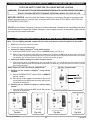
CONVERTING THE MANUAL-VALVE OUTDOOR CAMPFYRE™
To convert the Outdoor Campfyre™ from propane to natural gas, or from natural to propane gas, carefully follow
the steps below:
1. THE GAS SUPPLY TO THE OUTDOOR CAMPFYRE™ (AND ANY NEARBY ELECTRICAL SOURCES
AND APPLIANCES) MUST BE SHUT OFF.
2. If present, remove all logs and Lava Chunks from the Outdoor Campfyre™, and remove decorative tile top.
3. Remove the four (4) screws attaching the burner pan to the fire ring or enclosure.
4. Detach the thermocouple (taking care not to kink it) from the safety valve (see Fig. 25-2 for location). Remove
the ignitor wire from the ignitor module (see Fig. 25-3).
5. Carefully detach flex connector attached to the orifice holder (see Fig. 25-4) and unscrew the orifice holder
from the burner pipe (see Fig. 25-5).
6. Remove the orifice from the holder (see Fig. 25-5) and replace it with an orifice of the proper size. Propane
requires a #43 orifice. Natural gas requires a #14 orifice.
Note: If you are converting to and using natural gas, you MUST fit the air shutter in place over the burner pipe
(see Fig. 25-5). Remove the air shutter for propane gas. Replace the orifice holder and reattach the
connector from the valve (see Fig. 25-2). The regulator must now be converted to the new gas type.
7. The regulator is situated after the valve (see Fig. 25-2), behind the control panel, under
the tile top. To convert the regulator to the required gas type:
a) Unscrew and remove the cap (Fig. 25-1) from the regulator.
Note: As installed, the regulator cap may be located underneath the regulator. If necessary,
carefully rotate the regulator to access the cap.
READ GAS
TYPE HERE
(SHOWING PROPANE)
b) Remove the converter (the red plastic stalk, Fig. 25-1) by carefully pulling it away
from the center of the cap (it will snap out of its seat).
c) Place the opposite end of the stalk into the center of the cap (it will snap into
place).
d) Check that you can read the type of gas the unit will burn on the stalk as shown
in Fig. 25-1.
Regulator stalk removed
Fig. 25-1
Note: Each end of the plastic converter is embossed with either the letters "NAT" or "L.P." for the
respective gas type ("NAT" for natural - "L.P." for propane). When the converter is in the cap
and the cap held above the stalk, the letters (at the bottom of the stalk) indicate the gas that the
regulator is set up for. (Fig. 25-1 shows the converter set for propane gas.)
e) Replace the cap and converter into the regulator and screw down until snug.
8. Once the above steps are complete, reattach the thermocouple and ignitor wire (steps 4-5 in reverse). Fasten
the burner pan back into place on the Outdoor Campfyre™ ring. Restore the gas supply and check for leaks,
using soapy water. When no leaks are detected, replace the Lava Chunks and logs as described in the LAVA
CHUNK AND LOG PLACEMENT section. The Outdoor Campfyre™ is now ready for use. Follow the procedures
in the LIGHTING INSTRUCTIONS section for lighting the Outdoor Campfyre™.
Fig. 25-2
Fig. 25-3
Ignitor wire
(Detach when changing
orifice for different gas type.
Replace before use.)
Valve
Thermocouple wire
(Detach this when
changing gas type.
Reattach before use.)
Fig 25-4
Regulator
(Remove cap to convert
when changing gas
type. Replace before
use.)
Fig. 25-5
Connector from valve attached
to orifice holder on burner pipe
Orifice
(Remove to change for
Orifice
different gas type)
holder
#43-propane
Burner
#14-natural
pipe
Air shutter
(Use only with natural gas)
Detach connector from the orifice holder when changing the
orifice to a different gas type
REV 10 - 0710110811
Ignitor module
(rear view)
25
L-A2-18207
PETERSON OUTDOOR CAMPFYRE™ LIMITED WARRANTY
THREE (3) YEAR LIMITED WARRANTY
All Peterson Outdoor Campfyre logs, enclosures, and burner component parts, (except valves and controls) are covered by a three
(3) year limited warranty.
All Peterson valves and controls are covered by a separate one (1) year limited warranty (excluding batteries).
PLEASE KEEP A COPY OF YOUR SALES SLIP FOR PROOF OF PURCHASE
This warranty applies to the original purchaser and to single family residential use only. It commences from date of purchase, and is valid only with
proof of purchase.
This warranty does not cover parts becoming defective through misuse, accidental damage, electrical damage, improper handling, storage, and/or
installation. Product must be installed (and gas must be connected) as specified in the instructions or operator’s manual, by a qualified professional
installer. Accessories, parts, valves, remotes, etc., when used must be Peterson Co. product.
This warranty does not apply to rust, corrosion, oxidation, or discoloration, unless the affected component becomes inoperable. It does not cover
labor or labor-related charges.
This warranty specifically excludes liability for indirect, incidental, or consequential damages. Some states do not allow the exclusion or limitation of
incidental or consequential damages, so the above exclusion may not apply to you. This warranty gives you specified legal rights, and you may have
other rights that may vary from state to state.
For additional information regarding this warranty, or to place a warranty claim, contact the R.H. Peterson dealer where the product was purchased.
ROBERT H. PETERSON CO.
Quality Check
Date:___________
Orifice # (Main):__________
Orifice # (Other):__________
Leak Test:
___________
Burn Test:
___________
Gas Type:
NAT. / PROPANE
Model #:
___________
Serial #:
___________
Air Shutter: ___________
Inspector: ___________
Robert H. Peterson Co. • 14724 East Proctor Avenue • City of Industry, CA 91746
26