1
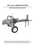
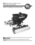
DR® ALL-TERRAIN™ MOWER
Assembly, Installation & Maintenance Instructions for the 42" Lawn Mower Deck
Figure 1
Important!
Please read the Assembly, Installation & Maintenance Instructions as well as the Safety and Operating
Instructions for the DR© All Terrain Mower to become familiar with the basic features of the DR® 42
Lawn Mower Deck before operating it.
Country Home Products, Inc.
Safety Information
We want you to enjoy years of productive use from your DR® 42 Lawn Mower. We don't want you to
get injured, so please take a few moments to read the following guidelines for safely operating your new
machine.
Dress Appropriately
•
Wear safety glasses while mowing to protect your eyes from thrown objects.
•
Wear shoes with non-slip treads when using your DR® 42 Lawn Mower. If you have safety shoes, we
recommend that you wear them. Do not use the machine while barefoot or wearing open sandals.
•
Wear long pants while mowing, and avoid loose clothing or jewelry, which might get caught in brush
or on the mower's moving parts.
•
Use ear muffs or ear plugs to protect your valuable hearing.
•
We recommend wearing gloves while mowing.
Preparation
•
Read these Safety & Operating Instructions, the Safety & Operating Instructions for the DR® All Terrain
Mower as well as the engine manufacturer's owner's manual before you use the DR® All Terrain
Mower with the DR® 42 attachment. Become familiar with the controls, engine and service
recommendations to ensure the best performance from your machine.
•
Inspect the area you'll be working in for hidden objects such as large rocks, logs, rope, wire, garden
tools, etc., and remove these obstacles before mowing. Mowing over such obstacles could damage
the machine and cause injury.
Operating the Machine Safely
•
Keep bystanders at least 100 feet away from your work area at all times. Objects can be thrown far
from the mower and at great speeds. To be safe, do not operate the machine near small children or
pets, and never allow children to operate the mower. Disengage the blades and stop the engine when
another person approaches.
•
Be sure all blade and wheel controls are DISENGAGED before attempting to start the engine.
Engage and disengage the blade control a few times to get used to it before mowing.
•
NEVER remove the shields from the mower, or alter the deck in any way.
WARNING! Keep your hands and feet away from the blades, belts, chains,
blade pulleys, and concealed areas while the engine is running. NEVER
reach under the deck when the engine is running.
2
DR® ALL-TERRAIN™ MOWER Assembly, Installation & Maintenance Instructions for the 42" Lawn Mower Deck
•
ALWAYS shut off the engine and remove the spark plug wire prior to making any adjustments to the
machine. If you have to stop to remove grass or debris from the underside of the deck, always
disconnect the spark plug wire first.
•
The exhaust area on the engine becomes very hot. Allow the engine to cool before doing
maintenance or making adjustments.
•
Keep combustible substances away from the engine when it is hot.
•
When operating over uneven terrain and slopes, use EXTREME CAUTION and make sure you're
on firm footing at all times.
•
Mow only during the daylight hours.
•
Use extra caution when mowing in wet, slippery conditions.
•
ALWAYS OPERATE THE MOWER FROM BEHIND. Never pass or stand on the discharge
(right) side or in front of machine when the engine is running.
•
DO NOT, under any conditions, remove, cut, bend, weld or otherwise alter standard parts on your
DR® 42 LAWN MOWER. This includes all shields and guards. Unauthorized modifications can
make the equipment unsafe and may void your warranty.
•
While using the DR® 42 LAWN MOWER, don't hurry or take things for granted. When in doubt
about the equipment or your surroundings, stop the machine and take the time to look things over.
Make sure that you have 100% control of the mower at all times.
Safety with Gasoline-Powered Machines
•
•
•
•
•
•
Do not run the engine in an enclosed area or without proper ventilation.
Store all fuel in containers specifically designed for this purpose. Plastic containers are more likely to
prevent sediment and condensation problems.
Fill the gasoline tank outdoors with the engine off. Don't handle gasoline if you or anyone nearby is
smoking, or if you're near anything that could cause it to ignite or explode.
If gas is spilled, do not attempt to start the engine. Move the machine away from the area of the spill
and avoid creating any source of ignition until the gas vapors have dissipated. Wipe up any spilled
fuel to prevent a fire hazard, and properly dispose of the waste.
Allow the engine to cool completely before storing in any enclosure. Never store the machine near
an open flame or spark with gas in the tank.
Do not change the engine governor settings or modify the engine speed.
The Fine Print…
Country Home Products, Inc. reserves the right to discontinue, change and/ or improve its products at
any time without notice or obligation to the purchaser. The descriptions and specifications contained in
this manual were in effect at printing. Equipment described within this manual may be optional. Some
illustrations may not be applicable to your machine.
DR® ALL-TERRAIN™ MOWER Assembly, Installation & Maintenance Instructions for the 42" Lawn Mower Deck
3
Safety/Operation Labels
Always replace damaged or missing safety and operation labels immediately.
136491
157641
164381
179401
4
DR® ALL-TERRAIN™ MOWER Assembly, Installation & Maintenance Instructions for the 42" Lawn Mower Deck
To Assemble the Lawn Mower Deck
WARNING! Always remove the spark plug wire
before servicing your machine.
Tools & Supplies Needed:
• Pliers
•
•
Hammer
½" socket or wrench
Mount the Front Caster Wheels
Mount the caster wheels on the front arms of the deck
frame as shown in Figure 1.
•
Insert the 4 black castor bushings into the top and
bottom of the lawn deck frame for both castors.
You may need to tap the bushings in with a hammer
(Figure 2).
•
Push the cotter pin as far as it will go as shown
(Figure 2).
•
Hold the tire with one hand to keep the axle from
turning while bending the legs of the cotter pins
with pliers.
•
Bend the long leg first, then the shorter leg (Figure
3).
Bushing
Figure 2
Grease
Fitting
Figure 3
WARNING! If you remove the cotter pins, replace them with new ones 1/4" in
diameter and 1-1/2" long. Repeated straightening and bending will break the cotter pins
at the bend, and may cause the caster wheels to come off during operation causing severe
damage or possible injury.
DR® ALL-TERRAIN™ MOWER Assembly, Installation & Maintenance Instructions for the 42" Lawn Mower Deck
5
Install the Discharge Chute
1. If your lawn mower deck shipped separately from
your DR® ALL-TERRAIN™ MOWER, you'll also
need to install the discharge chute. From below,
insert the bolts up through the holes in the deck.
2. Set the discharge chute in place, fit the bracket over
the bolts and tighten with the nuts (Figure 4).
To Remove the Brush Deck
WARNING! Always disconnect the spark
plug wire before servicing your machine.
1. Remove the black belt guard by unscrewing the
black knob, lifting the cover and pulling up and
back to remove it.
2. Release the belt tension lever (Figure 5).
3. Remove the belt from the pulley (Figure 6).
4. Remove the pin and collar (Figure 7), then pull the
power unit away from the deck.
Caution: Do not pull the deck away from the
power unit unless you have someone holding the
handlebars to prevent it from falling backward.
Belt Removed
Figure 6
6
Figure 4
Belt Tension Lever
Figure 5
Remove Pin & Collar
Figure 7
DR® ALL-TERRAIN™ MOWER Assembly, Installation & Maintenance Instructions for the 42" Lawn Mower Deck
To Install the Lawn Mower Deck
Your lawn deck is shipped with the belt in place on the two blade drive pulleys. However, occasionally
the belt comes off during shipping. If this occurs remove the two smaller belt covers with a ½" in
wrench or socket and place the belt back on the pulleys as shown in Figure 9 on Page 8.
1. Remove the black rectangular belt cover. Remove the two smaller black covers if necessary.
2. Line up the lawn mower deck with the
power unit and mount the deck.
3. Attach the collar and insert the pin
(Figure 8).
4. Mount the belt on engine pulley. If
necessary, place the belt around the
other pulleys as shown on the belt label
except for the pulley attached to the belt
release lever.
5. Push the belt release lever and set the
out side of the belt against the flat idler
pulley on the release lever. Hint: some
people push the lever with their foot.
Figure 8
6. Replace the belt covers.
DR® ALL-TERRAIN™ MOWER Assembly, Installation & Maintenance Instructions for the 42" Lawn Mower Deck
7
Maintenance
To Replace the Deck Belt
WARNING! Always disconnect the spark
plug wire before servicing your machine.
Tools Needed:
• 7/16" wrench and/or socket
• 1/2" wrench
• 3/16" Allen wrench
1. Remove the black rectangular belt cover.
For illustration purposes, belt is shown above
2. Remove the two smaller black belt covers.
springs, etc. Actual installation will be below.
3. Push the belt release lever.
4. Remove the belt from the deck pulleys and the Figure 9
engine pulley.
5. Remove the lower bolt on the rear hanger
plates (Figure 10). Swing the hanger plates
out of the way so the belt clears. Remove
the belt.
6. To mount the new belt, follow the above
procedure in reverse. See Figure 9 for correct
belt travel on the pulleys.
Lubrication
WARNING! Always disconnect the spark
plug wire before servicing your machine.
Tools & Supplies Needed:
• Flexible hose grease gun
• Lithium grease
• FLUID FILM® or similar lubricant
Figure 10
Unless instructed otherwise, pump only until you
feel slight resistance (1-2 pumps).
1. Grease the fittings on the front caster wheels
(Figure 11).
2. Grease the fittings on the lawn deck frame
where the castors swivel. (Page 5, Figure 3).
Tire Pressure
Maximum tire pressure is 46 psi in each front
caster wheel.
Figure 11
8
®
™
DR ALL-TERRAIN MOWER Assembly, Installation & Maintenance Instructions for the 42" Lawn Mower Deck
To Remove the Blades
WARNING! Always disconnect the spark plug wire before servicing your machine.
Tools Needed:
• 9/16" wrench or socket
• Rag or gloves to handle the blade
Note: You may want to block the blade with a piece of wood between the blade and the deck to hold
it while turning the nut.
1. Remove the blade bolt, lock washer and blade washer.
Caution: Be aware of the sharp blade when pushing or pulling the wrench.
2. Remove the blade.
3. Repeat with the other blade.
To Replace the Blades
1. Mount the blade, blade washer, lock washer and blade bolt, in that order, and tighten securely
(Torque 30-40 ft-lbs.).
Instructions for Leveling the DR® 42 Lawn Deck
The DR® 42 Lawn Deck settings made at the
factory are suitable for most purposes, however
leveling adjustments can be made if desired.
WARNING! Always disconnect the spark
plug wire before servicing your machine.
Tools Needed:
• 1/2" wrench or adjustable wrench
• 3/16" hex key
Note: All references to Left and Right are from
the Operator's position.
1. Move the machine to a level area.
2. Turn the machine off and disconnect the
spark plug wire.
3. Remove the belt covers and locate the
adjustment brackets (Figure 12).
4. Level the deck from front to back:
Note: You should adjust the deck so the back is
1/4" higher than the front. This will give you the
best cut.
Figure 12
DR® ALL-TERRAIN™ MOWER Assembly, Installation & Maintenance Instructions for the 42" Lawn Mower Deck
9
•
Measure the distance from the ground to the deck
at the front and back of the deck (Figure 13).
•
Adjust the deck from front to back as needed by
moving to a different hole in the rear adjustment
bracket (Figure 14). Each hole in the top of the
bracket will adjust the deck height by 1/16".
•
Fine adjustment of the front to rear deck tilt (less
than 1/4" change) is accomplished by moving both
front bracket-mounting bolts to different holes in
the adjustment brackets (Figure 15). Each hole
change in the front brackets will adjust the rear
deck height by 1/16".
•
Each hole in the bottom of the rear brackets
will raise or lower the rear of the deck by 1/2".
The rear of the deck can be lowered an
additional 1/2" by using the outside hole in the
top of the rear bracket.
•
Coarse adjustment of the front to rear deck tilt
(greater than 1/4" change) is accomplished by
moving the bolts in the bottom holes of the rear
brackets to raise or lower the rear of the deck by
1/2". The rear of the deck can be lowered an
additional 1/2" by moving the bolts in the top
holes of the rear bracket to the outside holes.
Figure 13
Figure 14
5. Level the deck from side to side:
•
Measure the distance from the ground to the
deck on the left and right sides of the deck
(Figure 13).
•
Adjust the deck as needed by moving to a
different hole in the bracket (Figure 15). Each
hole in the bracket will change the deck height
on that side by 1/4".
Figure 15
10
DR® ALL-TERRAIN™ MOWER Assembly, Installation & Maintenance Instructions for the 42" Lawn Mower Deck
Adjusting the Cutting Height
You can adjust the cutting height of the mower in 1/2" increments by
moving the lever on the side of the deck (Figure 16).
Mowing Tips for Best Performance
Turns
• Use a low gear when turning. This will give you better control and a
Figure 16
cleaner cut.
Slopes
• Use a low gear on slopes for better control, and avoid shifting gears until you're on flatter terrain.
Be ready to use the brake, if necessary.
Reverse
• Disengage the blade before shifting into reverse and backing up. Mowing in reverse is not safe.
• Be very careful of your footing when operating the machine in reverse. Know what's behind you
and take your time.
• If you find it difficult to shift into reverse, lightly feather the clutch lever as you pull the shift lever
into reverse, then quickly release the clutch lever.
Heavy/Wet Grass
• Be very careful of your footing when mowing in wet conditions. Avoid steep slopes and other
possibly slippery areas.
• The best cut is achieved by mowing when the grass is dry. If you have to mow when the grass is
wet, use a lower, slower speed.
• We do not recommend using the optional mulching plate in wet and heavy growth.
Other Checks
•
•
•
•
•
Routinely check all the fasteners for looseness.
Inspect, replace or sharpen and balance the blades if they become dull. Never try to straighten a
bent blade. Dull or bent blades can cause excessive vibration and wear.
Be sure to replace the blades in the proper orientation.
If your deck lacks power, check the belt for wear. Also check the blade drive pulleys for looseness.
If you find a loose pulley, remove the pulley and inspect the pulley hub and blade spindle and
replace if worn or damaged. The pulley is designed to shear with severe loads or impact.
Immediately stop the mower and turn off the power unit if you accidentally hit anything. Check
everything thoroughly before you continue.
DR® ALL-TERRAIN™ MOWER Assembly, Installation & Maintenance Instructions for the 42" Lawn Mower Deck
11
42" Lawn Mower Deck Parts List
Ref# Part#
Description
Ref# Part#
1
2
151501
157141
3
4
5
6
7
8
9
10
11
12
13
14
15
16
17
18
19
20
21
22
23
24
25
26
27
28
29
30
31
32
33
34
35
36
151551
151491
151541
151531
157191
151631
151561
151591
123761
151701
150721
151481
151471
151271
151641
179311
157221
143661
151611
151621
110971
151601
150691
151711
165121
165161
101891
151681
151691
165141
151921
160281
110961
126851
LAWN DECK FRAME, 42"
LAWN DECK HEIGHT ADJUSTMENT
PLATE
LAWN DECK SHAFT HANGER
HANGER ROD BUSHING
FRONT LAWN DECK HANGER ROD
REAR LAWN DECK HANGER ROD
REAR LAWN DECK LINK PLATE
FRONT LAWN DECK LINK PLATE
LAWN DECK HEIGHT ADJUSTER LEVER
LINKAGE CONNECTOR
BUSHING, NYLON, 3/4" BORE
SPINDLE ASSEMBLY
BUSHING, 1.38" ID x 1.63" OD
LAWN DECK WITH PLATE
IDLER ARM, BELT RELEASE LEVER
PULLEY, FLAT, IDLER 4"
LAWN DECK ANTI-TORSION PLATE
WHEEL, CASTER
BUSHING, .265" ID x .370" OD
KNOB, HANDLEBAR 5/16" -18
GUARD, LEFT BELT COVER
GUARD, RIGHT BELT COVER
PIN, ROLL, 3/16" x 1-3/4"
SCREW, SHOULDER, 5/16" -18
BOLT, HCS 3/8" -16 x 2-1/2"
PULLEY, V BELT
SPINDLE NUT, 9/16-18, Hex Lock
SPACER, .675 ID x 1.125 OD, PULLEY
GREASE FITTING, 1/4" –28, STRAIGHT
STRIPPER
BLADE, 21" MULCHING
WASHER, .385 ID x 1.390 OD, BLADE
PIN HITCH (CLIP)
SPACER, .39 ID x 1 OD x .785 T
PIN, ROLL, 3/16" x 1"
PIN, COTTER, 3/16" x 1-1/2"
38
39
40
41
42
43
44
45
46
47
48
49
50
51
52
53
54
160851
160911
123371
151881
151901
150051
150631
Deleted
151281
157111
157101
157211
157231
157131
157321
157081
157311
55
56
57
58
59
60
61
62
63
64
65
67
68
69
70
71
72
73
150941
165131
114681
157301
145291
164131
110731
110761
121701
112381
112391
165151
151731
157121
120301
110751
Deleted
112371
37
151511
CASTER AXLE YOKE
12
De scription
MAIN BELT COVER
PIN, COTTER, 1/4" x 1 1/2"
BOLT, HCS, 3/8"-16 x 2 3/4"
DEFLECTOR
PIN, HINGE
SPRING, TORSION
BRACKET DEFLECTOR
BAFFLE VORTEX
BRACKET, RH ANTI-SCALPING WHEEL
BRACKET, LH ANTI-SCALPING WHEEL
BUSHING, 3/8" ID x 5/8" OD x 1.03 L
SPRING, E, 5"
SCREW, SHOULDER, 3/8" -16
NUT, 5/16" PUSH
WHEEL, ANTI-SCALPING
SCREW, 5/16" -18 x 1-1/4" TRI LOBE
THREAD FORMING
SPRING, E., .750" OD x .112" WIRE
BOLT, HCS, 3/8" -24 x 1-1/4", GR 8
BOLT, HCS, 1/4" -20 x 1-1/4", GR 2
BOLT, HCS, 1/4" -20 x 3/4", Gr 5
BOLT, 5/16" -18 x 3/4", CARRIAGE
NUT, NY LOCK, 3/8"-16 LOW PROFILE
NUT, NYLON LOCK, 1/4" - 20
NUT, NYLON LOCK, 5/16" - 18
WASHER, FLAT, 3/8" SAE ANSI NARROW
WASHER, FLAT, 1/4" USS, ANSI WIDE
WASHER, FLAT, 3/8" USS, ANSI WIDE
WASHER, LOCK, .385 ID x .691 OD
BELT, A100, 1/2" x 102"
BOLT, HCS 3/8" -16 x 2-1/4"
SCREW, 3/8"- 16 x 1-1/2"
NUT, NYLON LOCK, 3/8" - 16
WASHER, FLAT, 10-24
DR® ALL-TERRAIN™ MOWER Assembly, Installation & Maintenance Instructions for the 42" Lawn Mower Deck
Frame Assembly
DR® ALL-TERRAIN™ MOWER Assembly, Installation & Maintenance Instructions for the 42" Lawn Mower Deck
13
Deck Assembly
14
DR® ALL-TERRAIN™ MOWER Assembly, Installation & Maintenance Instructions for the 42" Lawn Mower Deck
Height Adjuster Assembly
DR® ALL-TERRAIN™ MOWER Assembly, Installation & Maintenance Instructions for the 42" Lawn Mower Deck
15
COUNTRY HOME PRODUCTS®
Meigs Road, P.O. Box 25, Vergennes, VT 05491
1-800-DR-OWNER (376-9637) • www.dr-owner.com
©2004 CHP, Inc. 157661