1
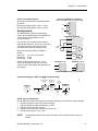
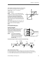
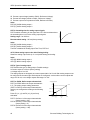
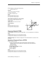
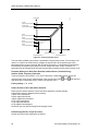
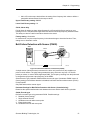
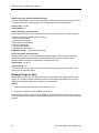
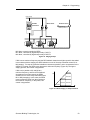
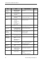
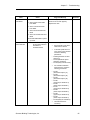
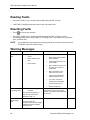
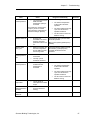
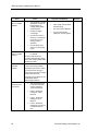
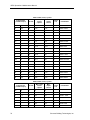
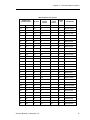
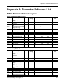
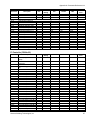
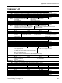
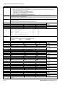
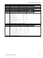
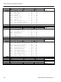
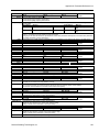
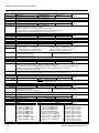
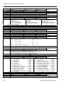
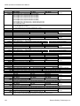
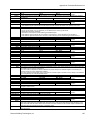
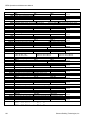
Appendix A: Parameter Reference List
Min: 50
Details:
Note:
P1203
Def: 100
Max: 200
Level 3
Defines search current used for flying start.
Value is in [%] based on rated motor current (P0305).
Reducing the search current may improve performance for flying start if the inertia of the system is not very high.
Search rate: Flying start
Min: 50
Details:
Example:
Note:
P1210
Def: 100
Max: 200
Level 3
Sets factor by which output frequency changes during flying start to synchronize with turning motor. Enter this value in [%]
relative to default time factor (which defines the initial gradient and influences time taken to search for motor frequency).
The search time is the time taken to search through all possible frequencies (between [f_max+2*f_slip] and 0 Hz).
P1203=100% is defined as giving a rate of 2% of f_slip,nom/[ms].
P1203=200% would result in a rate of frequency change of 1% of f_slip,nom/[ms].
For a motor with 50 Hz, 1350 rpm, 100% would produce a maximum search time of 600 ms. If the motor is turning, the
motor frequency is found in a shorter time.
A higher value produces a flatter gradient and thus a longer search time.
A lower value has the opposite effect.
Automatic restart
Min: 0
Enum:
Dependency:
Caution:
Note:
P1211
P1212
P1213
P1230[2]
Details:
Settings:
Index:
Caution:
Note:
P1232
Def: 1
Max: 5
Level 2
0=Disabled
3 =Restart after fault/mains break: P1211 enabled
1 =Trip reset after power on:
P1211 disabled
4 =Restart after mains break:
P1211 enabled
2 =Restart mains break; power on:
P1211 disabled
5 =Restart mains break/fault/power on: P1211 disabled
Auto restart requires constant ON command (for example, via a digital input wire link).
Settings 2 to 5 can cause the motor to restart unexpectedly
Flying start must be used in cases where the motor may still be turning (for example, after a short mains break) or can be
driven by the load (P1200).
Number of restart attempts
Min: 0
Def: 3
Max: 10
Level 3
Time to first restart
Min: 0
Def: 30
Max: 1000
Level 2
Restart time increment
Min: 0
Def: 30
Max: 1000
Level 2
BI: Enable DC braking
Min: 0:0
Def: 0:0
Max: 4000:0
Level 3
Enables DC braking via a signal applied from an external source. Function remains active while external input signal is
active.
DC braking causes the motor to stop rapidly by applying a DC braking current (current applied also holds shaft stationary).
When the DC braking signal is applied, the inverter output pulses are blocked and the DC current is not applied until the
motor has been sufficiently demagnetized.
722.0=Digital input 1 (requires P0701 set to 99, BICO)
722.1=Digital input 2 (requires P0702 set to 99, BICO)
722.2=Digital input 3 (requires P0703 set to 99, BICO)
722.3=Digital input 4 (requires P0704 set to 99, BICO)
722.4=Digital input 5 (requires P0705 set to 99, BICO)
722.5=Digital input 6 (requires P0706 set to 99, BICO)
722.6=Digital input 7 (via analog input 1, requires P0707 set to 99)
722.7=Digital input 8 (via analog input 2, requires P0708 set to 99)
P1230[0] : IN000 (AUTO) 1st. Command data set (CDS)
P1230[1] : IN001 (HAND) 2nd. Command data set (CDS)
Frequent use of long periods of DC braking can cause the motor to overheat.
This delay time is set in P0347 (demagnetization time). If this delay is too short, overcurrent trips can occur.
DC braking current
Min: 0
P1233
Def: 100
Max: 250
Level 2
Duration of DC braking
Min: 0
Value:
Caution
Note:
Def: 0
Max: 250
Level 2
P1233=0 : Not active following OFF1.
P1233=1-250 : Active for the specified duration.
Frequent use of long periods of DC braking can cause the motor to overheat.
The DC braking function causes the motor to stop rapidly by applying a DC braking current (the current applied also holds
the shaft stationary). When the DC braking signal is applied, the inverter output pulses are blocked and the DC current not
applied until the motor has been sufficiently demagnetized (demagnetization time is calculated automatically from motor
data).
Siemens Building Technologies, Inc.
115