1
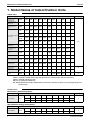
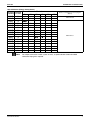
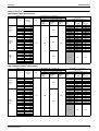
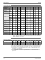
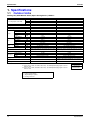
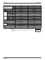
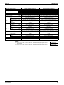
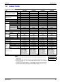
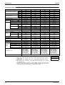
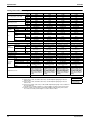
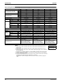
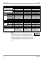
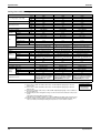
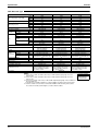
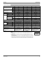
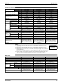
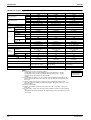
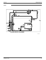
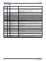
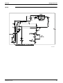
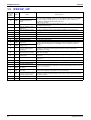
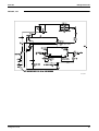
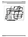
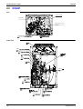
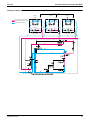
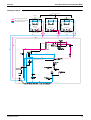
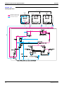
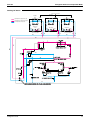
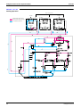
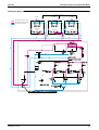
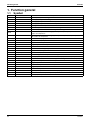
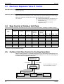
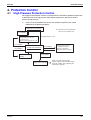
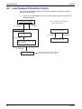
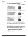
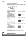
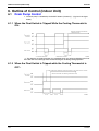
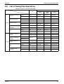
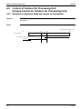
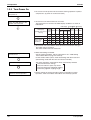
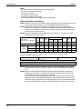
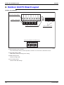
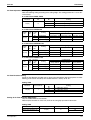
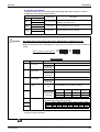
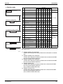
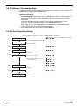
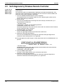
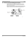
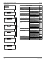
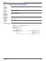
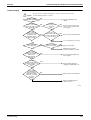
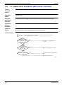
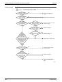
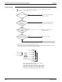
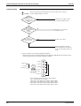
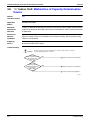
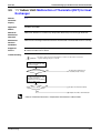
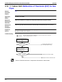
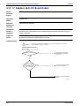
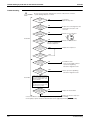
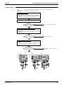
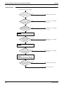
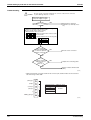
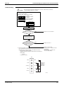
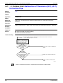
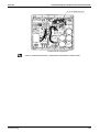
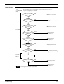
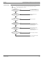
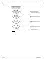
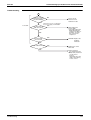
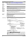
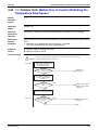
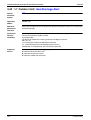
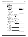
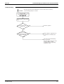
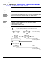
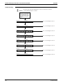
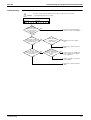
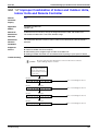
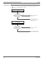
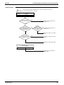
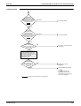
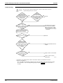
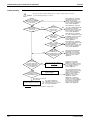
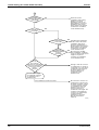
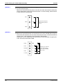
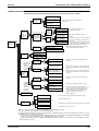
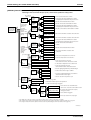
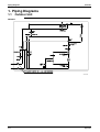
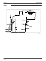
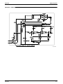
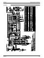
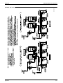
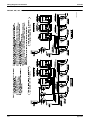
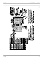
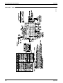
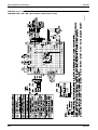
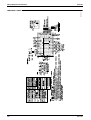
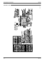
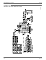
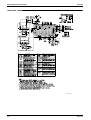
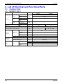
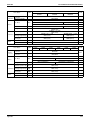
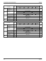
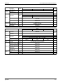
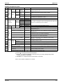
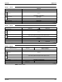
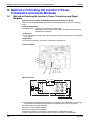
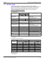
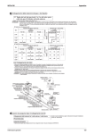
Refrigerant Circuit
1.3
Si34-704
RXQ10P, 12P
No. in
refrigerant
Symbol
system
diagram
Major Function
A
M1C
Inverter compressor (INV)
B
M2C
Standard compressor 1
(STD1)
D
M1F
Inverter fan
Since the system is of air heat exchanging type, the fan is operated at 9-step rotation
speed by using the inverter.
E
Y1E
Electronic expansion valve
(Main: EV1)
Fully open.
F
Y2E
Electronic expansion valve
(Subcool: EV3)
PI control is applied to keep the outlet superheated degree of subcooling heat
exchanger constant.
G
Y1S
Solenoid valve (Hot gas: SVP) Used to prevent the low pressure from transient falling.
J
Y2S
Solenoid valve (Oil return: SVO) Used to return oil from the accumulator to the compressor.
M
Y3S
4-way valve
Inverter compressor is operated on frequencies between 52Hz and 210Hz by using
the inverter, while Standard compressor is operated with commercial power supply
only. The number of operating steps is as follows when Inverter compressor is
operated in combination with Standard compressor.
RXQ10, 12P : 37 steps
Fixed to cooling operation.
N
S1NPH High pressure sensor
Used to detect high pressure.
O
S1NPL Low pressure sensor
Used to detect low pressure.
S1PH
HP pressure switch (For INV
compressor)
Q
S2PH
HP pressure switch (For STD
compressor 1)
U
—
Pressure regulating valve
(Liquid pipe)
This valve opens at a pressure of 4.0 MPa for prevention of pressure increase, thus
resulting in no damage of functional parts due to the increase of pressure in
transportation or storage.
V
—
Subcooling heat exchanger
Used to subcool liquid refrigerant from the electronic expansion valve (cooling) or
indoor units (heating).
W
—
Capillary tube
Used to return the refrigerating oil separated through the oil separator to the INV
compressor.
X
—
Capillary tube
Used to return the refrigerating oil separated through the oil separator to the STD1
compressor.
1
R1T
Thermistor (Outdoor air: Ta)
Used to detect outdoor temperature, correct discharge pipe temperature, and others.
2
R2T
Thermistor (Suction pipe: Ts)
Used to detect suction pipe temperature.
3
R31T
Thermistor (INV discharge
pipe: Tdi)
4
R32T
Thermistor (STD1 discharge
pipe: Tds1)
5
R4T
Thermistor (Heat exchanger
deicer: Tb)
Used to detect liquid pipe temperature of air heat exchanger.
6
R5T
Thermistor (Subcooling heat
exchanger gas pipe: Tsh)
Used to detect gas pipe temperature on the evaporation side of subcooling heat
exchanger, keep the superheated degree at the outlet of subcooling heat exchanger
constant, and others.
Used to detect liquid pipe temperature.
P
64
Name
In order to prevent the increase of high pressure when a malfunction occurs, this
switch is activated at high pressure of 4.0 MPa or more to stop the compressor
operation.
Used to detect discharge pipe temperature, make the temperature protection control of
compressor, and others.
7
R6T
Thermistor (Liquid pipe: Tl)
8
R7T
Thermistor (Accumulator inlet) Used to detect gas pipe temperature at the accumulator inlet.
Refrigerant Circuit