1
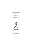
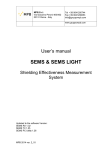
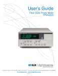
Operating Manual
Model 101 3-Channel
DC Signal Conditioner Amplifier
Measurement Specialties, Inc.
Vibration Sensors Design Center
32 Journey, Suite 150
Aliso Viejo, CA 92656 USA
Tel: 949-716-5377
www.meas-spec.com
[email protected]
Operating Manual Model 101, Revision 1
Page 1 of 14
Table of Contents
Warranty ...........................................................................................................................3
Safety .............................................................................................................................. 4
Description ...................................................................................................................... 5
Specifications .................................................................................................................. 6
Wiring Information ........................................................................................................... 7
Front Panel ...................................................................................................................... 9
Rear Panel ..................................................................................................................... 10
Setting Up the Model 101 .............................................................................................. 11
Location of Filter Modules and Rsh Resistors ............................................................... 14
Operating Manual Model 101, Revision 1
Page 2 of 14
Warranty
Measurement Specialties, Inc. instruments are
warranted during a period of one year from
date of shipment to original purchaser to be
free from defects in material and workmanship.
The liability of Seller under this warranty is
limited to replacing or repairing any instrument
or component thereof which is returned by
Buyer, at Buyer’s expense, during such period
and which has not been subjected to misuse,
neglect, improper installation, repair, alteration,
or accident. Seller shall have the right to final
determination as to the existence and cause of
a defect. In no event shall Seller be liable for
collateral or consequential damages. This
warrant is in lieu of any other warranty,
expressed, implied, or statutory; and no
agreement extending or modifying it will be
binding upon Seller unless in writing and
signed by a duly authorized officer.
Receiving Inspection
Every Measurement Specialties, Inc.
instrument is carefully inspected and is in
perfect working condition at the time of
shipment. Each instrument should be checked
as soon as it is received. If the unit is damaged
in any way, or fails to operate, a claim should
immediately be filed with the transportation
company.
Service Concerns
If a Measurement Specialties, Inc. instrument
requires service, first contact the nearest
Measurement Specialties, Inc. representative.
They may be able to solve the problem without
returning the unit to the factory. If it is
determined that factory service is required, call
Customer Service at the regional headquarters
for an RMA number before return.
Operating Manual Model 101, Revision 1
Page 3 of 14
Returns
All units being returned to the factory require
an RMA (Return Material Authorization)
number before they will be accepted. This
number may be obtained by calling Customer
Service at the regional headquarters with the
following information; model number(s),
quantity, serial number(s), and symptoms of
the problem, if being returned for service. You
must include the original purchase order
number if under warranty.
Inquiries
Address all inquiries on operation or
applications to the End User Applications
Support as follows:
Global Headquarters
1000 Lucas Way
Hampton, VA 23666, USA
Tel: +1 757 766 1500
Vibration Sensors Design Center
32 Journey, Suite 150
Aliso Viejo, CA 92656, USA
Tel: +1 949 716 5377
European Headquarters
105 av. du Général Eisenhower
BP 1036, 31023 Toulouse Cedex, France
Tel: +33 (0) 561 194 543
Asian Headquarters
Measurement Specialties (China), Ltd.
F1.6-4D, Tian An Development Compund
Shenzhen, China 518048
Tel: +86 755 8330 1004
Email: [email protected]
Web: www.meas-spec.com/vibration
Safety
Read this manual in its entirety before operating the Model 101 Signal Conditioner. Read all wiring and power
hookup instructions and understand the requirements prior to using another manufacturer's products with the
Model 101. Insure that any product being interfaced with the Model 101 is wired according to prevailing local
safety and operational standards before operating.
The following symbols and terms may be found on the Model 101 and its manuals and indicate important
information.
When found on the device, this symbol indicates that the operator should refer to the manual
for important instructions on the proper use of this device. When found in the manual, this
symbol indicates that the reader should understand the implications contained in the text
before operating the device.
This symbol indicates that a shock hazard may be present. Read the instruction manual
carefully and insure that the device is wired properly and that all settings have been checked
prior to applying power to the device.
The WARNING label indicates important information that should be heeded for safe and proper
performance of the device.
The CAUTION label is used to indicate that damage to the power supply or equipment connected to it
could occur if directions are not followed. Warranty could be invalidated if the instructions in this manual
are not followed.
Disassembling the Instrument
Turn Input Power Switch OFF before removing power cable from the instrument.
Remove power cable from instrument before disassembling any part of the instrument.
Grounding
To avoid electrical shock, the power cord protective grounding conductor must be
connected to power ground.
Fuse Replacement
For continued fire protection, replace fuse only with the specific type and rating by
qualified personnel (Reference Manual "Rear Panel" section). Disconnect the power
cord before replacing fuse.
Operating Manual Model 101, Revision 1
Page 4 of 14
Description
The Model 101 is a new, microprocessor-controlled, 3-Channel DC Signal Conditioner Amplifier designed to be
used with bridge type or differential output accelerometers and pressure transducers. The Model 101
incorporates variable gain adjustment, shunt calibration capability, and multiple excitation level settings. For
various applications where specific frequency roll-off is required, the Model 101 offers a variety of optional filter
modules. Measurement Specialties new 3-Channel DC Signal Conditioner offers a multitude of features in a
simple bench top enclosure for ease of use.
The Model 101 utilizes a microprocessor SLEEP mode to eliminate high frequency clock noise and their
associated harmonics. The microprocessor WAKES momentarily to acknowledge front panel switch depressions
then goes to SLEEP immediately after processing and executing the requested function. This allows the
amplifiers to operate with minimum self generated noise and provides clean, clock free amplified signals.
The Model 101 uses dual 12-bit DAC's, for each channel, to autozero the input and output amplifiers for DC
input signals. Input signals with magnitudes of +/-10 Vdc can be zeroed. Unzeroing the amplifier zeroes both
autozero DAC's. A unique output DAC trimming routine, allows trimming the output zero to within +/-1mVdc.
Dual 12-bit DAC's, for each channel, are also used to set amplifier gains from 0.00 to 999.9 with +/-0.5%
precision. Amplifier gains can be changed "on the fly" without damage to the instrument.
Each of the 3 amplifiers has a 150kHz full power and a 200kHz small signal bandwidth and can drive 10mA into
a 1K ohm load. A low pass filter socket is provided, for each amplifier, to filter broadband noise. A variety of
optional filter modules can be installed in these sockets.
The transducer excitation supplies are individually adjustable for each channel from 0.00 to 12.00Vdc. Any
setting above 12.00Vdc will generate an excitation voltage of 12.10Vdc. The outputs are short circuit protected
and can supply up to 30mA each. Remote sense leads are provided to eliminate errors caused by long cable
lengths.
The Model 101 has been CE tested for compliance to EN61326 for EMC emissions and immunity and
EN61010-1:2001 for Product Safety.
Consult Measurement Specialties Application Engineers for associated optional filter modules and cable
assemblies to mate with the Model 101.
Operating Manual Model 101, Revision 1
Page 5 of 14
Specifications
Input Specifications
Input Range
Input Impedance
Common Mode Input Range
Common Mode Rejection
Autozero Adjustment Range
Autozero Accuracy
Output Specifications
AC/DC Voltage
Output Impedance
Linear Output
Current Output
Output DC Bias Temp Stability
Output DC Bias Time Stability
Excitation Voltage
Excitation Voltage Accuracy
Excitation Current
Noise & Ripple
Transfer Characteristics
Gain Range
Resolution
Accuracy
Linearity
Noise
Frequency Response
Filter
Crosstalk Between Channels
Power Requirements
Voltage
Current Rating
Isolation
Physical Characteristics
Dimensions
Weight (w/o power cord)
Case Material
Operating Manual Model 101, Revision 1
Differential 0 to +/-10Vdc or peak Vac, 9-pin D-sub connector for each
bridge sensor
> 1 Megohm minimum
+/- 10Vdc or peak Vac, inclusive of signal 50V peak without damage
70db minimum, 200 ohms or less imbalance, DC to 60kHz, gain >100
20db typ, 200 ohms or less imbalance, DC to 60kHz, gain =1
+/-10mVdc for gain<1000
+/-100mVdc for gain≤100
+/-1Vdc for gain ≤10
+/-10Vdc for gain ≤1
Within +/-50mV (typ)
Single ended, short circuit protected, isolated from power ground
0.2 ohms max
10Vpeak
10mA min
+/-5uV/degC RTI or +/-0.1mV/degC RTO whichever is greater
+/-20uV RTI or 5mV RTO, whichever is greater for 24hrs, after 1hr
warmup
0 to 12Vdc, front panel selectable for each channel
+/-1% (0 to 10Vdc), +/-5% (12Vdc)
30mA maximum per channel, short circuit protected
1mVrms maximum, 10Hz to 50kHz, with 1 kOhm load
0.00 to 999.9
For 0 ≤ gain <10, 0.00 to 9.99
For 10 < gain <100, 10.00 to 99.99
For 100 < gain <1000, 100.0 to 999.9
+/-0.5% of full scale (max), DC to 1kHz, filters disabled
+/-0.1% of full scale, best fit straight line at 1kHz reference
20uVrms RTI plus 1mVrms RTO, whichever is greater DC to 50 kHz,
with a 1kohm source resistance unit (with 10 kHz internal low pass filter
enabled)
DC to 150 kHz (full power bandwidth), -3db referenced to 1kHz
Plug in module (optional)
80 db RTI
100/115/230V~, 50/60 Hz, rear panel switch selectable
0.1/0.1/0.05 A
No isolation channel to channel or signal ground to case ground
8.25”w x 3.25”h x 9.25”d (210 x 83 x 235mm)
3.4lbs (1.5kg)
Iridited aluminum
Page 6 of 14
Wiring Information
CH1, CH2 and CH3 (9-Pin Standard D-Subminiature) Transducer Connector
1 - Sense(+)
2 - NC
3 - NC
4 - Vin(-)
5 - Vin(+) Note: Vin(+) and Vin(-) are fully differential inputs
6 - Sense(-)
7 - Vexc(+)
8 - Vexc(-) Note: Vexc(-) is connected to analog ground.
9 - NC
Recommended Hookup for Bridge Type Sensors (Sense leads wired for optimum performance)
Typical Hookup for Bridge Type Sensors (Alternate sense lead wiring)
Operating Manual Model 101, Revision 1
Page 7 of 14
Wiring Information
CH1, CH2 and CH3 Output BNC Connector (50 ohm)
Typical Hookup to Oscilloscope
Note:
The Model 101 Signal Ground is isolated from power ground. This allows connecting the
oscilloscope Power Ground to the 101 Signal Ground. To minimize high frequency EMI
susceptibility, install clamp-on ferrites with frequency bands of 80MHz to 800MHz.
Operating Manual Model 101, Revision 1
Page 8 of 14
Front Panel
SW1 (Gain / Excitation)
SW2 (Shunt Cal Switch)
SW3 (Channel Select Switch)
LED1 (Channel Select LED)
SW4 (Zero / Unzero Switch)
SW5 (Set Gain Switch)
SW6 (Set Vexc Switch)
LED2 (Power On LED)
Operating Manual Model 101, Revision 1
Sets Gain from 0.00 to 999.9 or Vexc from 0.00 to 12.00Vdc
Activates Shunt Cal Relay and Internal Shunt Cal Resistor
Used to select Channel to update
Illuminates when corresponding Channel is selected
Zeroes, Unzeroes, or Trims Zero of selected Channel
Sets Gain to Thumbwheel Switch setting of selected Channel
Sets Vexc to Thumbwheel Switch setting of selected Channel
Illuminates when V~, 50/60 Hz input power is applied
Page 9 of 14
Rear Panel
Operating Manual Model 101, Revision 1
Page 10 of 14
Setting Up the Model 101
To setup CH1, CH2 or CH3, perform the following steps in the sequence shown.
Step 1: Set Vexc
1. Set the GAIN/EXCITATION Thumbwheel Switch (SW1) to desired Vexc.
Note: If the Thumbwheel Switch is set to a value >12.00, Vexc will be 12.10 Vdc.
For 0.00 < or = Thumbwheel Switch Setting < or = 12.00, Vexc will be equal to
the Thumbwheel Switch Setting, when selected.
2. Depress the Channel Select Switch for CH1, CH2 or CH3. The appropriate Channel Select
LED will illuminate and stay illuminated.
3. Depress the SET Vexc Switch (SW6). The Channel Select LED will extinguish and Vexc for
the selected channel will be set to the Thumbwheel Switch setting.
Example: Set Thumbwheel Switch to 009.75. Depress CH2 switch, then the SET Vexc
Switch. Vexc for CH2 should be 9.75Vdc +/-1%.
Step 2: Set Amplifier Gain
1. Set the GAIN/EXCITATION Thumbwheel Switch (SW1) to desired amplifier gain.
Note: The amplifier gain can be set anywhere from 0.00 to 999.9.
2. Depress the Channel Select Switch for CH1, CH2, or CH3. The appropriate Channel Select
LED will illuminate and stay illuminated.
3. Depress the SET GAIN Switch (SW5). The Channel Select LED will extinguish and the
selected channel gain will be set to the Thumbwheel Switch setting.
Example: Set the GAIN/EXCITATION Thumbwheel Switch to 075.00. Depress CH2 switch,
then the SET GAIN switch. CH2 gain will be set to 75.00.
Step 3: Zero the Amplifier
1. Verify the input to the appropriate channel is the desired input to be zeroed.
Note: Any DC input signal, within the specified operating range of the amplifier can be
zeroed.
2. Depress the Channel Select Switch CH1, CH2, or CH3. The appropriate Channel Select LED
will illuminate and stay illuminated.
3. Depress and release the ZERO Switch (SW4).
4. The amplifier, under microprocessor control, will first zero the output of the input amplifier,
then zero the output of the output amplifier. The output will be 0.00 +/- 0.050Vdc (typ).
Operating Manual Model 101, Revision 1
Page 11 of 14
Step 4: Trimming the Zero output
Note: Trimming allows the user to zero the output of the selected channel to within
±1mVDC. This trimmed value may then be stored in non-volatile memory and
reapplied upon power turn on.
1. Perform Step 3: Zero the Amplifier.
2. Depress and hold depressed, the Channel Select Switch for CH1, CH2 or CH3. The
appropriate Channel Select LED will illuminate and stay illuminated.
3. To increment the output zero by 1 count of the output zero DAC, set the GAIN/EXCITATION
Thumbwheel Switch (SW1) to " 0 0 0. 0 1 ".
To decrement the output zero by 1 count of the output zero DAC, set the GAIN/EXCITATION
Thumbwheel Switch (SW1) to " 0 0 1. 0 1 ".
4. Depress the ZERO switch. The output zero will increment or decrement by 1 count of the
output zero DAC. Successive depressions of the ZERO switch will continue to increment or
decrement the output zero.
Note: To increment the output zero by (x) counts of the output zero DAC, set the
GAIN/EXCITATION Thumbwheel Switch (SW1) to " 0 0 0. 0 x " and depress the
ZERO switch.
To decrement the output zero by (x) counts of the output zero DAC, set the
GAIN/EXCITATION Thumbwheel Switch (SW1) to " 0 0 1. 0 x " and depress the
ZERO switch.
5. To save the trimmed zero value in non-volatile memory, depress and hold depressed the
Channel Select switch again. The selected channel LED will extinguish. The trimmed zero
value will be stored in non-volatile memory.
Note: If any other channel is selected before the selected channel switch is depressed
and held, the trimmed zero value will not be saved and the previously stored
zero value will be used at power up.
Operating Manual Model 101, Revision 1
Page 12 of 14
Setting Up the Model 101
Unzeroing the desired channel.
Note:
Unzeroing the desired channel sets both autozero DAC's to zero. This basically
sets the amplifier to its natural zero position. The output of the amplifier is offset
by its own offset voltage.
Step 1: Unzero the amplifier
1. Depress the Channel Select Switch for CH1, CH2 or CH3. The appropriate Channel Select
LED will illuminate and stay illuminated.
2. Depress and hold the ZERO Switch (SW4) until the appropriate Channel Select LED
extinguishes. The selected Channel amplifier is unzeroed.
Applying an internal shunt calibration resistor (Rsh) to the selected channel bridge network.
Note:
Internal solder jumpers allow for a positive or negative responding Rsh. The shunt
cal resistors are removable and may be installed by the user.
Reference Location of Filter Modules and Rsh Resistor in the following page.
Turn Input Power Switch OFF before removing power cable from the
instrument. Remove power cable from the instrument before disassembling
any part of the instrument.
1. Simply depress and hold the Rsh Switch for the desired channel amplifier. The shunt cal
resistor is applied to the appropriate transducer bridge circuit terminals for the duration that
the Rsh Switch is depressed.
Operating Manual Model 101, Revision 1
Page 13 of 14
Location of Filter Modules and Rsh Resistors
Operating Manual Model 101, Revision 1
Page 14 of 14