1
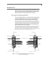
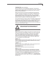
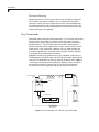
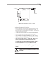
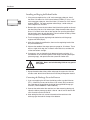
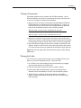
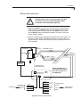
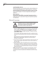
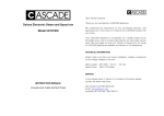
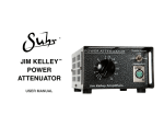
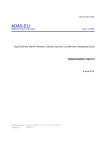
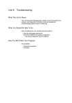
Valco Instruments Co. Inc. Pulsed Discharge Detector Models D-2 and D-2-I Instruction Manual Rev 2/14 North America, South America, and Australia/Oceania contact: Valco Instruments Co. Inc. 800 · 367· 8424sales 713 · 688· 9345tech 713 · 688· 8106fax [email protected] Europe, Asia, and Africa contact:: VICI AG International Schenkon, Switzerland Int + 41 · 41 · 925· 6200phone Int + 41 · 41 · 925· 6201fax [email protected] This page intentionally left blank for printing purposes Table of Contents Introduction Description and Operating Principles...............................................................1 Safety Notes and Information...........................................................................3 Symbols Installation Category Safety Maintenance Components of the Detector System...............................................................4 Description of Controls.....................................................................................4 Specifications...................................................................................................9 System Requirements Components not Included with the Detector System.....................................10 System Purity.................................................................................................10 Gas Specifications.........................................................................................11 GC Column Selection....................................................................................12 Installation General Precautions......................................................................................13 Mounting the Detector on the GC..................................................................13 Gas Connections...........................................................................................14 Installing and Purging the Gas Regulator..............................................15 Installing and Purging the Helium Purifier..............................................16 Connecting the Discharge Gas to the Detector......................................16 Column Connection.......................................................................................17 Testing for Leaks............................................................................................17 Electrical Connections...................................................................................19 Initial Power-Up..............................................................................................20 Troubleshooting High Background Current....................................................21 Checking for Leaks in the Discharge Gas Plumbing..............................21 Column Bakeout Precautions.................................................................22 Mode Selection and Setup Helium Ionization Mode.................................................................................23 Selective Photoionization Mode.....................................................................23 Electron Capture Mode..................................................................................25 Appendix: PD-C2 Controller (shipping February 2014) Attenuated output...................................................................................29 Unattenuated outputs.............................................................................30 Zero Function ........................................................................................30 Electrical Connections...................................................................................30 Note About Compatibility...............................................................................31 Warranty...............................................................................................................32 Detector Performance Log....................................................................................33 This page intentionally left blank for printing purposes 1 Introduction NOTE: The contents of this manual apply to either the HID/ECD dual mode detection system (D-2) or the HID single mode detection system (D-2-I). In general, the manual describes the dual mode detector; information which applies specifically to the single mode detector is so indicated. Description and Operating Principle The pulsed discharge detector is a non-radioactive universal detector which can easily be configured to function as a helium ionization detector (HID), photoionization detector (PID), or electron capture detector (ECD). A schematic representation of the two configurations is shown in Figure 1. As the name implies, a stable, low power, pulsed DC discharge in helium is utilized as the ionization source. Elutants from the column, flowing counter to the flow of helium from the discharge zone, are ionized by photons from the helium discharge above. Resulting electrons are focused toward the collector electrode by the two bias electrodes. The principal mode of ionization is photoionization by radiation arising from the transition of diatomic helium He2(A1 ∑ u+ ) to the dissociative 2He(1S1) ground state. This is the well-known Hopfield emission. The photon energy from the He2 continuum is in the range of 13.5 eV to 17.7 eV. HELIUM INLET HELIUM INLET DISCHARGE ZONE DISCHARGE ZONE SPRING WASHERS SPRING WASHERS DISCHARGE ELECTRODES QUARTZ INSULATOR DOPANT INLET GROUND BIAS ELECTRODE GROUND QUARTZ INSULATOR BIAS ELECTRODE COLLECTOR ELECTRODE SAPPHIRE INSULATORS COLLECTOR ELECTRODE CAPILLARY COLUMN BIAS ELECTRODE SAPPHIRE INSULATORS CAPILLARY COLUMN VENT VENT DOPANT INLET COLUMN INLET COLUMN INLET Figure 1: Schematic of the D-2 detector in the PDECD mode (left) and the PDHID mode (right) Introduction 2 Helium Ionization (PDHID) The PDHID is essentially non-destructive (0.01 - 0.1% ionization) and highly sensitive. The response to organic compounds is linear over five orders of magnitude with minimum detectable quantities (MDQs) in the low or sub picogram range. The response to fixed gases is positive (the standing current increases), with MDQs in the low ppb range. For trace analysis of fixed gases optimized for packed columns (low ppb range), we offer a modified version of the detector dedicated to the ionization mode (Product Number D-2-I). The PDHID response is universal except for neon, which has an ionization potential of 21.56 eV. Since this potential is close to the energy of the He* metastable (19.8 eV) but greater than the photon energy from the He2 continuum, neon exhibits a low ionization efficiency and low detector response. (NOTE: Valco makes an enhanced mode detector for neon. Consult the factory for information.) Photoionization (PDPID) Changing the discharge gas from pure helium to helium doped with argon, krypton, or xenon changes the discharge emission profile, resulting in resonance atomic and diatomic emissions of the rare gas added. Response is limited to sample compounds with ionization potentials less than or equal to the dopant gas emission energy. In this configuration, the detector is essentially functioning as a specific photoionization detector for selective determination of aliphatics, aromatics, and amines, as well as other species. Since there is no lamp or window, sensitivity will not change with time. Electron Capture (PDECD) In the electron capture mode, the PDECD is a selective detector for monitoring compounds with high electron affinity such as CFCs, chlorinated pesticides, and other halogenated compounds. The MDQ for this type of compound is at the femtogram (10-15) level. Response characteristics and sensitivity are similar to those of a radioactive 63Ni ECD. In addition to minor configuration changes, running in the ECD mode requires the addition of a dopant gas (recommended is 3% xenon in helium). The dopant gas is first ionized by the photons from the discharge. Resulting electrons, in the absence of any electron-capturing compounds, constitute the detector standing current. Electron capture processes occur when electron capturing compounds enter the detector, resulting in a decrease in the detector standing current which constitutes the PDECD response. That the constant-potential ECD response is not linear over a wide range is well known. The signal from the PDECD is best described by: (Ib - Ie)/Ie = KA x [A] where Ib is the detector standing current, Ie is the detector current measured in the presence of analyte, A, KA is the electron capture coefficient, and [A] is the concentration of A. The majority of commercially available ECDs use a variable frequency, constant-current technique to increase the linear Introduction 3 dynamic range whereas, in the D-2, a unique system of feedback to the bias electrode is employed. It operates by comparing the detector output current to a reference value and changing the bias voltage to maintain the detector current at the reference value. (E.g., in the presence of an electroncapturing compound, the bias voltage must be raised to maintain constant detector current.) The bias voltage, scaled to an appropriate range, is the linearized output signal representing the concentration of the capturing compound. This results in a linear dynamic range of more than five orders of magnitude. The feedback is incorporated in such a way that it is bypassed in the PDHID mode. Safety Notes and Information Symbols HIGH VOLTAGE Voltages presenting the risk of electric shock are present in several places in the equipment. Avoid contact with hazardous live parts. Do not probe into openings or attempt to defeat safety mechanisms. HOT SURFACE The surface of the detector body may be hot while in operation (possibly in excess of 250°C). Caution should be observed. ATTENTION Refer to the manual. PROTECTIVE EARTH This internal connection provides protection against electric shock from mains voltages and should not be removed. Installation Category This equipment has been designed for installation category (overvoltage category) II, pollution degree 2. It has been approved for use in heavy industrial environments. It has been tested to EN Class A limits and may not be used in residential environments. Safety This instrument has been designed and tested in accordance with the product safety standard, EN61010. It has left the factory in a safe condition. This instruction manual contains important information and warnings which must be followed by the user to insure safe operation and to retain the instrument in a safe condition. The case, chassis, and measuring terminals are connected to the protective earth contact of the mains inlet. The instrument operates with a three-conductor power cord having a protective earthing conductor and a plug with an earthing contact. The Introduction 4 mains (line) plug shall only be inserted in a socket outlet provided with a protective earth contact. The protective action must not be negated by the use of an extension cord without a protective conductor. Use only with an approved mains supply cord having a rating of 2A, 250V, or greater. Do not use this equipment in a manner not specified herein. CAUTION: During normal operation, the detector produces ultraviolet energy (UVA, UVB), some of which may be emitted. Do not watch the arc without eye protection. Maintenance The exterior of the instrument should be cleaned regularly with a dusting brush. If necessary, the casing can be cleaned with a moistened cloth (99% water + 1% mild detergent). Spirit or petroleum ether can be used to remove greasy dirt. Any other cleaning agents can attack the plastic and painted surfaces. Under no circumstances should the cleaning fluid get into the instrument. Petroleum ether is flammable, and care should be taken in its use. Under no circumstances should the detector be disassembled for cleaning. The components of the detector are assembled with special tooling and held under considerable force. Disassembly of the detector may present a safety hazard and will result in its destruction. Components of the Detector Systems Components of the detector system are listed in Tables 1 and 2. Check the contents of the packages to verify that everything is present. Contact the factory if anything is missing or damaged. (NOTE: damaged shipments must remain with the original packaging for freight company inspection.) Description of Controls Controls and connectors are indicated in Figure 2. NOTE: In early 2014, we began shipping a redesigned controller. If the rear panel of your controller does not look like the one in Figure 2, please refer to the appendix on page 29. MAINS switch Controls mains (line) voltage to the controller unit. When this switch is on ( | ), the unit is operational except for the pulse supply (see the next paragraph). The detector heater will operate (if connected) and high voltage is present on the bias cables. DISCHARGE switch and indicator Controls power to the pulse supply module. When the switch is on and the module is connected, high voltage is generated by the unit and is present at the detector electrodes. The indicator will not light if the detector is in the standby mode, or if the pulse supply is not connected to the controller. The indicator flashes until the discharge has been established, then glows steadily. Introduction 5 Description Quantity Product number Detector cell, PDHID/PDECD 1 PD-D2 Pulse supply module 1 PD-M2 1 I-23477 1 PD-C2 Cable, computer (unattenuated) output 1 I-23136 Cable, recorder (attenuated) output 1 I-23483 Instruction manual 1 MAN-PDD Fittings kit 1 PD-KIT-ECD 1/32" polyimide ferrule 5 ZF.5V 1/16" gold-plated ferrule 5 ZF1GP 0.25 - 0.44 mm polyimide column ferrule 5 FS.4 0.4 - 0.5 mm polyimide column ferrule 5 FS.5 1/16" union 2 ZU1 1/16" tee 1 ZT1 1/8" external to 1/16" internal reducer 2 EZR21 1/8" to 1/16" reducing union 2 EZRU21 1/32" external nut 1 EN.5KN Vent tube 1 I-23212 Restrictor, 4 cc/min @ 30 psi He 1 TGA-R-04F30P Restrictor, 30 cc/min @ 60 psi He 1 TGA-R-30F60P Includes: Cable, controller to pulse supply Controller unit with power cord Includes: Includes: Table 1: Components of the D-2 system Description Quantity Product number Detector cell, PDHID 1 PD-D2-IS Pulse supply module 1 PD-M2 1 I-23477 1 PD-C2 Cable, computer (unattenuated) output 1 I-23136 Cable, recorder (attenuated) output 1 I-23483 Instruction manual 1 MAN-PDD Fittings kit 1 PD-KIT-HID 1/16" gold-plated ferrule 5 ZF1GP 1/16" union 2 ZU1 1/16" tee 1 ZT1 1/8" external to 1/16" internal reducer 1 EZR21 1/8" to 1/16" reducing union 1 EZRU21 Restrictor, 50 cc/min @ 50 psi He 1 TGA-R-50F50P Includes: Cable, controller to pulse supply Controller unit with power cord Includes: Includes: Table 2: Components of the D-2-I system Introduction 6 MODE SWITCH 200 CURRENT SWITCH 16 32 64 128 256 4 512 1024 2 1 240 160 TEMPERATURE CONTROL RANGE SWITCH 8 280 120 PDECD 1X INCREASE 320 80 360 40 400 DETECTOR TEMP. PDHID 10X DECREASE MODE RANGE CURRENT ATTENUATION CONTROL ATTENUATION TEMPERATURE INDICATOR DISCHARGE INDICATOR V ECD nA HID DISCHARGE SWITCH DISCHARGE ZERO PUSH BUTTON PULSED DISCHARGE CONTROLLER ZERO DISPLAY If your controller rear panel does not look like this, refer to the Appendix on page 29. VALCO INSTRUMENTS CO. INC. MODEL PD-C2 HEATER 115/230V ~ 175VA MAX 50/60 Hz HEATER OUTPUT MAINS INPUT FUSE MAINS SWITCH MAINS INPUT T2.0A 250V OUTPUTS WARNING: FOR CONTINUED PROTECTION AGAINST FIRE HAZARD, REPLACE FUSE WITH SAME TYPE AND RATING. ATTENTION: UTILISER UN FUSIBLE DE RECHANGE DE MÊME TYPE. SHIELD 1V 10V - COM UNATTEN ZERO + - PULSE SUPPLY SHIELD ATTEN PULSE SUPPLY DETECTOR INPUT: 15V MAX. CAT ATTENUATED OUTPUT UNATTENUATED OUTPUT ELECTROMETER BIAS-B BIAS-A Figure 2: Controls and connections on front (top) and rear panels of the control module Introduction 7 TEMPERATURE control and indicator Sets the temperature (°C) of the detector heater block. The indicator is steadily on when maximum power is being applied to the heater, steadily off when no power is applied, and regularly blinking on/off when the set temperature has been established. Note that due to the fail-safe mechanism designed into the temperature controller, the heater will not operate if mains power is applied before the heater is connected or if the detector is too cold (< 0°C). If the heater is disconnected with mains on, the unit must first be turned off to restore control of the heater; if the unit is operated in a very cold environment, the detector should first be gently warmed without power applied. The fail-safe mechanism will also act under any condition resulting from loss of control (e.g., over-heating, RTD failure, etc.). If proper procedures have been followed and the controller will not heat the detector, there is cause to suspect that the fail-safe mechanism has been activated. Consult the factory or an authorized representative. Note that the maximum temperature for operation of the PD-D2-IS is 400°C. Heater control may be lost during periods of fast electrical transients. The unit will self-recover. MODE switch Determines the operational mode of the controller and unzeroes the signal output (see discussion under ZERO push button). This switch changes the bias voltages supplied to the electrodes as required for each detection mode. In the PDHID mode the bias voltages are set at -200 and the linearization circuit is inactive; in the PDECD mode the bias voltages are internally controlled and the detector output is linearized. (Note that the D-2-I cannot operate in the PDECD mode.) RANGE switch Determines the full-scale range of the electrometer: 100 nA @ 1X, or 10 nA @ 10X. In PDECD mode, the high detector background current normally restricts operation to the 1X range. CURRENT switch Sets the standing current in PDECD mode. Pressing at the top increases the current, pressing at the bottom decreases the current. ATTENUATION control Determines the attenuation factor for the recorder output. ZERO push button Offsets the output signal to zero volts by a measurement of the standing current. The offset is applied to the output when the button is released. Once set, the offset is not changed unless the unit is re-zeroed or the mode is changed. To remove any applied offset and restore the unit to an unzeroed condition, toggle the MODE or RANGE switch. The function of this control is duplicated by an external logic connection; see UNATTENUATED OUTPUT below. Introduction 8 Display Indicates standing current in the PDHID mode or bias voltage in the PDECD mode, auto-scaled to the most suitable range. In the un-zeroed PDHID mode, the display indicates the instantaneous signal current in nA. After zeroing, the display indicates the standing current by which the signal is offset. In the PDECD mode, the display indicates the controlling bias voltage unless the CURRENT switch or ZERO button is pressed, when it indicates the set current. ATTENUATED OUTPUT connector Normally connected to a strip chart recorder. This output has an unattenuated range of 0 - 10V, and an internal signal reference (-) at zero volts. For best noise performance, the shield (earth) and signal reference (-) should not be connected together. The signal from this output is scaled by the attenuation factor set on the front panel. UNATTENUATED OUTPUT connector Normally connected to a data acquisition system or other recording means. For convenience, a full-scale 0 - 10V output and a 1/10 scale 0 - 1V output are provided, with an internal signal reference (-) at zero volts. For best noise performance, the shield (earth) and signal reference (-) should not be connected together. The internal impedance of these outputs is 1000 ohms. The connection marked ZERO is a low-true, 5V logic-level input which duplicates the function of the front-panel ZERO; connection of this input to COM through either a relay contact or logic gate is equivalent to pressing the ZERO button. HEATER OUTPUT connector For connection to the detector heating system. ELECTROMETER INPUT cable For connection to the collector electrode of the PD detector. The full-scale input current is determined by the RANGE switch. Input voltages in excess of 15 VDC may result in damage to the electrometer. BIAS A, B OUTPUT cables For connection only to the bias electrodes of the PD detector in the manner described on page 19 under the heading “Electrical Connections”. These outputs supply high voltages when power is applied to the unit, and caution should be observed when connecting or disconnecting these cables. NOTE: These terminals are for connection only to equipment having no accessible live parts. Insulation of external circuits to which these are connected must meet the requirements of EN61010 for 220 VDC working voltage. Introduction 9 Specifications Mains (line): Fuse: Pressure: 115/230 V~50/60 Hz, 175 VA 2 A, time-delay, 5 x 20 mm 6.9 kPa (1 psi) operating, 6.9 MPa (1000 psi) max. working Maximum temperature PD-D2-IS: 400°C PD-D2: 400°C Heater power: 60 W max., 48 V, PWM Sensitivity 10X range: 1.0 V/nA 1X range: 0.1 V/nA ± 1%* Range 10X: 10 nA full-scale 1X: 100 nA full-scale* Noise 1X: 20 fA/√Hz (referred to the input), 0.1 - 10 Hz* 10X: 5 fA/√Hz (referred to the input), 0.1 - 10 Hz Risetime: 10 msec, 10% = 90%* Output impedance: < 1 Ω, attenuated 1 KΩ, unattenuated, 1 V, 10 V Environmental ratings: 10°C - 50°C, 10% - 95% relataive humidity *Controller only, PDHID mode, 10 V unattenuated output 10 System Requirements Components Not Included with the Detector System •Helium (99.999% purity) and other support gases •Ultra high purity grade gas pressure regulator with stainless steel diaphragm •Any special adapters required for connection to the gas regulator •Flow measuring device System Purity Discharge/Carrier Gas Considerations The performance of the detector is adversely affected by the presence of any impurities in the gas streams (carrier, discharge, or dopant). We recommend that a quality grade of helium 5.0 (99.999% pure or better) be used at all times. Major gas suppliers offer research grade helium (99.9999% pure) which is particularly low in fixed gas impurities and should give good results in a clean system, but even the highest quality carrier gas may contain some water vapor and fixed gas impurities; hence a helium purifier is included as part of the detector system. The discharge gas must always be run through the helium purifier. Whenever a new batch of discharge gas is received, we recommend performing a blank GC analysis of the gas in the PDHID mode to detect and identify the presence of any impurities. Gas purity requirements are specified in the next section. Tubing Standards of cleanliness that are suitable for many GC applications may be totally inadequate for the sensitive PDHID/PDPID/PDECD work. All surfaces that contact the gas stream must be glass or stainless steel. Do not use copper tubing or brass fittings. All tubes must be thoroughly cleaned and baked before use. Flow Controllers The use of valves or flow controllers in which the gas stream is exposed to any polymer-based packing or lubricating material is to be particularly avoided. Pressure Regulators We recommend commercial “ultra-pure” grade regulators with stainless steel diaphragms. Regulators with diaphragms made of neoprene or other elastomers should never be used. System Requirements 11 Gas Specifications For Model D-2 Detector Mode PDECD PDHID Ar-PDPID Kr-PDPID Xe-PDPID Discharge gas Helium Helium 2% Ar in He Carrier gas Helium Helium * ** ** Dopant gas 3% Xe in He n/a n/a n/a n/a 1.5% Kr in He 0.8% Xe in He ** Any gas including He which has an ionization potential greater than 12 eV ** Any gas including He which has an ionization potential greater than 11 eV The helium purifier (HP2) supplied with the system must be used for the discharge gas. Purity Specifications •Helium (discharge and carrier gas) must have a minimum purity of 99.999%, with < 20 ppm Ne impurity. For trace analysis of fixed gases, we strongly recomment 99.9999% purity He with < 0.5 ppm Ne. •Ar-PDPID mode: •Kr-PDPID mode: •Xe-PDPID mode: 2% ± 0.3% Ar in 99.999% He balance 1.5% ± 0.1% Kr in 99.999% He balance 0.8% ± 0.2% Xe in 99.999% He balance For Model D-2-I Detector Mode PDHID Ar-PDPID Discharge gas Helium 2% Ar in He Carrier gas Helium * Kr-PDPID Xe-PDPID 1.5% Kr in He 0.8% Xe in He ** ** ** Any gas including He which has an ionization potential greater than 12 eV ** Any gas including He which has an ionization potential greater than 11 eV Purity Specifications •Helium (discharge and carrier gas) must have a minimum purity of 99.999%, with < 20 ppm Ne impurity. For trace analysis of fixed gases, we strongly recomment 99.9999% purity He with < 0.5 ppm Ne. •Ar-PDPID mode: •Kr-PDPID mode: •Xe-PDPID mode: 2% ± 0.2% Ar in 99.999% He balance 1.5% ± 0.1% Kr in 99.999% He balance 0.8% ± 0.2% Xe in 99.999% He balance System Requirements 12 GC Column Selection To prevent detector contamination, we strongly recommend disconnecting the column from the detector during column bakeout procedures. PD-D2 The PD-D2 is optimized for packed columns with OD of 1/16" or less. Some of the stationary phases may not be compatible due to higher column bleed, manifesting in high detector background current. If you must use a packed column or a metal or metal-coated fused silica capillary column, consult the factory for more information. Best detector performance is obtained with bonded phase fused silica capillary columns with an ID between 0.25 - 0.32 mm. Megabore columns can be used, but the column flow rate should not exceed 15 mL/min. Excessive column flow rates may allow diffusion of the analytes into the discharge region. PD-D2-IS The PD-D2-IS is optimized for 1/8" packed columns. The column tubing must be thoroughly cleaned and baked before the column is packed. Even when the best care is taken in column tubing cleaning and in the support and stationary phase selection, a new column will often bleed compounds, resulting in a considerable increase in the detector baseline. This initial bleed will usually be reduced to acceptable levels after the column is conditioned with clean carrier gas flow for several hours at the recommended bakeout temperature. The PD-D2-IS can also be used with megabore columns. 13 Installation The detector is usually mounted on top of the GC column oven. The cabling as supplied requires the discharge module to be located within 0.6 m (2') of the detector and the controller to be within 1 m (3.5') of the detector and discharge module. The power cord for the controller is 1.8 m (6') long, and the signal output cables (attenuated and unattenuated) are 1.2 m (4') long. General Precautions •Do not use plastic/polymer or copper tubes for gas handling and interconnectons. Use only stainless steel tubing with Valco gold-plated ferrules. •Do not turn the unit on until the helium discharge gas is flowing through the detector. •Do not shut off or disconnect the discharge gas when the detector is hot, even if the unit is turned off. Turn off both power switches (front and back of the controller) and allow the detector to cool down naturally before disconnecting or shutting off the discharge gas. •Do not cover the unit with materials or devices which would restrict air circulation. •Position the controller unit where the mains switch on the rear panel can be reached easily. Mounting the Detector on the GC Vertical Mounting Most GCs have an existing opening which will allow the PDD to sit vertically on top of the column oven with the column inlet manifold (PD-D2, top) or tube (PD-D2-IS, bottom) extending into the oven. (The PD-D2-IS vent tube can either extend into the oven or be carefully bent near the base to remain outside the oven.) If you are replacing an existing detector, you can usually just remove it and set the PDD in its place. If not, use a drill or chassis punch to drill a hole of the proper size, and set the detector in position. While trying to match the mounting holes of the base plate to every GC on the market is impractical, we have located the mounting holes so that at least two of them will coincide with existing holes on the GC. If you had to drill a new hole to mount the PDD, you will have to drill new mounting holes as well. Orient the detector to allow for easy cable and gas connections. DOPANT GAS INLET (ECD MODE) DOPANT PD-D2 DISCHARGE GAS INLET VENT VENT COLUMN INLET MANIFOLD COLUMN INLET NUT DISCHARGE GAS INLET PD-D2-IS COLUMN INLET TUBE VENT TUBE Installation 14 Horizontal Mounting Some older GCs have access to the column oven through the side of the GC. This does not present a problem as far as operation of the PDD is concerned. Drill a hole at the appropriate location, orient the detector for convenient connection, and mark the position of the mounting holes. Drill the mounting holes and secure the detector to the side of the GC with four sheet metal screws (not supplied). Gas Connections Remember these three points discussed earlier: (1) all surfaces that contact the gas stream must be glass or stainless steel; (2) do not use copper tubing or brass fittings; and (3) all tubes must be thoroughly cleaned and baked before use. The installation instructions below assume that the detector discharge will be supplied from a nearby cylinder of helium of the proper purity. If your installation is different, you may need to modify the instructions appropriately. A number of Valco fittings have been supplied in the fittings kit to handle different situations. Figure 3 illustrates gas connections for a typical detector system using a PD-D2 detector in the ECD mode. For HID and PID modes, disconnect the restrictor TGA-R-04F30P, cap the line, and plug the dopant inlet. Figure 4 illustrates gas connections for the PD-D2-IS detector system. Since the distance from the helium supply to the GC varies from installation to installation, we do not supply tubing to go from that point to the GC. DISCHARGE GAS INLET DOPANT VENT TGA-R-30F60P RESTRICTOR (30 mL/min minimum) TEE (ZT1) HELIUM PURIFIER VENT DISCHARGE GAS (99.999% He) COLUMN INLET COLUMN INJECTOR GAS CHROMATOGRAPH DOPANT GAS (3% Xe in He) TGA-R-04F30P RESTRICTOR Figure 3: Gas connections for a PD-D2 in the ECD mode Installation 15 DISCHARGE GAS INLET TGA-R-50F50P RESTRICTOR (50 mL/min minimum) TEE (ZT1) HELIUM PURIFIER DISCHARGE GAS (99.999% He) COLUMN INLET COLUMN INJECTOR GAS CHROMATOGRAPH VENT Figure 4: Gas connections for a PD-D2-IS system Installing and Purging the Gas Regulator 1. Make sure the on/off valve on the helium cylinder is completely closed. Screw the CGA fitting nut of the regulator into the helium cylinder. Go beyond finger-tight, but do not tighten the nut all the way – some leakage is required for the purging operation. 2. Turn the output pressure regulating knob completely counterclockwise. 3. Open the cylinder on/off valve slightly and quickly close it again. 4. Adjust the tightness of the regulator connecting nut to allow a pressure reduction of ~690 kPa/sec (100 psi/sec). With a new bottle, the gauge should start out at about 14 MPa (2000 psi). 5. When the pressure drops into the 1.4 - 3.4 MPa (200 - 500 psi) range, open the cylinder on/off valve slightly and quickly close it again. 6. Repeat Step 5 eight or ten times to be certain that all the air is purged. On the final purge, tighten the regulator connecting nut very securely as the pressure approaches the 2.1 - 3.4 MPa (300 - 500 psi) range. 7. Open the cylinder valve to pressurize the regulator once again. Close the valve and observe the needle of the high pressure gauge for 15 minutes. If it doesn’t move, there is no critical leak on the high pressure side of the regulator. CAUTION: Never use leak detecting fluids on any part of this system. Installation 16 Installing and Purging the Helium Purifier EZR21 1. If the pressure regulator has a 1/8" male cone-type outlet port, install the Valco 1/8" external to 1/16" internal reducer (EZR21); if it has a 1/4" male cone-type outlet port, install the Valco 1/4" external to 1/16" internal reducer (EZR41). For other regulator outlet fittings, a wide variety of Valco adapters are available. 2. Remove the cap from the inlet tube of the Valco helium purifier and insert the tube fitting into the 1/16" reducer port. (Keep the outlet tube capped.) Use a 1/4" wrench to turn the nut one-quarter turn past the point where the ferrule first starts to grab the tubing. Do not remove the fitting. When made up properly, it should be leak-tight. 3. Turn the output pressure regulating knob clockwise until the gauge registers 345 KPA (50 psi). 4. Allow five minutes for equilibration, then turn the regulating knob all the way counterclockwise. 5. Observe the needle of the output pressure gauge for 15 minutes. There will be a slight initial drop, but if it doesn’t move after that, consider that all the connections are tight. 6. If necessary, use an electronic leak detector to locate any leaks. If a leak detector is not available, tighten all the fittings (including the output pressure guage), and repressurize the system for another test. CAUTION: Never use leak detecting fluids on any part of this system. 7. Upcap the outlet tube of the purifier and purge the system for 15 to 30 minutes at 60 - 80 mL/min to eliminate air from the purifier getter material. Connecting the Discharge Gas to the Detector 1. If you are supplying the GC from the helium purifier, use the Valco tee (ZT1). Otherwise, use one of the Valco 1/16" unions (ZU1) to connect the outlet tube of the purifier to the inlet of the supplied discharge gas restrictor (TGA-R-30F60P or TGA-R-50F50P). 2. Connect the outlet end of the restrictor to a flow measuring device and adjust the helium pressure to obtain a flow of ~30 mL/min for the PD-D2 and ~50 mL/min for the PD-D2-IS. 3. After setting the flow rate, connect the outlet of the restrictor to the discharge gas inlet tube at the top of the detector. Installation 17 Column Connection The following applies only to systems with the PD-D2 detector. On the PD-D2-IS detector, the column is connected to the column inlet tube with a 1/16" union, and does not extend into the detector. 1. Make a mark on the column at the length indicated below for PDHID or PDECD operation, as appropriate for your application. If a ruler is not handy, place the end of the column over the figure below to determine how far into the detector body the column must be inserted. Optimum length of column insertion in PDECD mode (101 mm) Optimum length of column insertion in PDHID mode (116 mm) 2. Remove the knurled nut and plug from the column inlet manifold at the bottom of the detector. Slide the nut over the end of the column, followed by the appropriate column ferrule (FS.4 or FS.5, or ZF.5V for megabore). 3. Insert the column through the column inlet manifold at the bottom of the detector. Slide it in until the mark is flush with the surface of the knurled nut, and secure the column by tightening the knurled nut finger tight only. Figure 5 on the next page shows how the column position affects detector performance. Testing for Leaks It is critical for the system to be leak-tight, and an additional check at this point can save many headaches later on. To test for leaks: 1. On a PD-D2, insure that the dopant inlet and vent outlet are plugged. Cap the vent outlet tube on the PD-D2-IS. 2. Pressurize the entire system with helium to 138 kPa (20 psi). 3. If the system does not hold pressure, check all the fittings with an electronic helium leak detector. DO NOT use leak detecting liquids. 4. Tighten fittings as required. (Further leak testing is described on page 21 in the section entitled “Checking for Leaks in the Discharge Gas Plumbing”). Installation 18 4.0 3.5 ECD Mode Detector temperature: 50 C Working current: 15 nA Sample: 50 ppb freon-11 2 l loop 3.0 Peak height (nA) 2.5 2.0 1.5 1.0 0.5 0.0 9.2 3.5 3.0 9.4 9.6 9.8 10.0 10.2 10.4 Length of column in detector (cm) 10.8 10.6 HID Mode Detector temperature: 50 C Sample: 100 ppm n-C5 2 l loop Peak height (nA) 2.5 2.0 1.5 1.0 0.5 0.0 10.6 10.8 11.0 11.2 11.4 Length of column in detector (cm) 11.6 11.8 Figure 5: Effect of column position on detector response in ECD and HID modes Installation 19 Electrical Connections CAUTION: Do not use a wrench to tighten the SMC connectors on the bias and electrometer cables. Connections should be finger tight only. 1. Referring to Figure 6 as necessary, connect the bias and electrometer cables as follows: the BIAS-B cable to the top electrode (closest to the discharge electrodes), the electrometer cable (ELECT) to the middle, and the BIAS-A cable to the bottom electrode. This setup is the same for both detector models. 2. Connect the high-voltage cable from the detector to the pulse supply, and connect the pulse supply cable between the back of the controller and the pulse supply. Connect the heater cable from the detector to the back of the controller. DETECTOR GROUND HIGH VOLTAGE ECD MODE: BIAS-B OPEN ELECT. HID MODE: ELECTROMETER BIAS-B BIAS-A BIAS-B ELECT. BIAS-A DISCHARGE MODULE HEATER CABLE FROM DETECTOR If your controller rear panel does not look like this, refer to page 31 in the Appendix. CONTROLLER (Rear panel) ATTENUATED OUTPUT RECORDER SHIELD + – RED BLACK GREEN WHITE RED BLACK WHITE GREEN BROWN BLUE ORANGE YELLOW 0 - 10 V Common 0-1V Shield COM SET Figure 6: Electrical connections UNATTENUATED OUTPUT AUTO ZERO COMPUTER OR INTEGRATOR Installation 20 Initial Power-Up NOTE: This section refers to the D-2 operating in the HID mode and to the D-2-I. For instructions on using the D-2 in the ECD mode, see page 25. However, we recommend that D-2 users test system integrity by proceeding with the instructions below before switching to the ECD mode. 1. Set the MODE switch on the front of the controller to PDHID. 2. Set the discharge gas flow as specified in on page 16 in the section entitled “Connecting the Discharge Gas to the Detector”. CAUTION: Always make sure that discharge gas is flowing before powering up the detector. 3. Apply power to the helium purifier. 4. Turn on the MAINS switch located on the back of the controller. 5. Set the detector temperature to 100°C with the TEMPERATURE control knob. Allow time for the detector and helium purifier to reach temperature. 6. Turn on the DISCHARGE switch, located on the front of the controller. The discharge should start within five minutes. (Once a system has been up and running, the discharge will start within a few seconds.) In a clean system, the discharge will have a peach/pink color. A purple discharge indicates impurities and/or leaks in the discharge gas stream. 7. Check the detector standing/background current, indicated in the LED DISPLAY on the controller, and record it in the Detector Performance Log on the last page of this manual. The optimum detector background current is 0.5 to 1.5 nA. The initial value may be higher, but as the detector bakes out at its operating temperature, the background current should decrease to the optimum value. 8. The recommended detector temperature is 20°C above the column temperature, with a minimum of 100°C. Set the detector to the operating temperature required for the intended analysis. When the detector has reached the set temperature, read and record the standing current. 9. Install the column as described on page 17, leaving the oven at ambient temperature. Start carrier flow, then read and record the standing current. The difference between this reading and the one previous is the ionization of the combined impurities in and eluting with the carrier gas. The smaller the difference, the better the quality of the gas exiting the column. 10. Set the column oven to the temperature required for the intended analysis. When the oven reaches the set temperature, read and record the standing current. The difference from the previous reading is the ionization of the column bleed. The smaller the difference, the better the column is conditioned. Installation 21 NOTE: Some stationary phases will have a higher bleed than others, but are still suitable for this detector. However, the lower the bleed, the lower the chances of contaminating the detector cell. From this point, the standing current should be observed and logged after any system change. In addition, logging the standing current (with and without the column) on a regular basis is an effective monitor of system integrity (leak-tightness and cleanliness). We also recommend tracking the internal standard (quantity on column/area count) for sensitivity continuity. Troubleshooting High Background Current If the background current does not drop below 2 nA even after a 12 hour bakeout, there is either a leak in the system or the column effluent is not clean. To see if the high background current is due to the column: 1. Make sure the controller is in the un-zeroed condition. (Refer to the discussion about the ZERO push button on page 7.) 2.For a PD-D2, loosen the knurled nut and pull the column out ~20 mm. Secure the nut. For a PD-D2-IS, completely disconnect the column from the column inlet tube, leaving the inlet open. 3. Watch the detector standing/background current, indicated in the controller DISPLAY. If the current remains high, then either the system has a leak in the discharge gas supply line or the discharge gas has impurities in it. Proceed to the next section, “Checking for Leaks in the Discharge Gas Plumbing”. If the current decreases dramatically, then either the carrier gas supply has leaks and/or contaminants, or the column is the source of contamination and needs a bakeout. Read the “Column Bakeout Precautions” on the next page before proceeding. Checking for Leaks in the Discharge Gas Plumbing Leaks can be detected with hydrogen. A small lecture bottle of hydrogen with a regulated flow of 10-15 mL/min through a small outlet tube is all that is required. (This method can only be used to detect leaks on the discharge gas side of the plumbing and between the column and detector inlet.) 1. Make sure the controller is in its un-zeroed condition. (Refer to the discussion about the ZERO push button on page 7.) 2. Hold the hydrogen outlet tube at a fitting connection for ten seconds while monitoring the standing current display on the controller. 3. If the current remains the same, proceed to the next fitting. If the current increases, there is a leak at that connection. Tighten the fitting and test it again, repeating as necessary until there is no change in the standing current. 4. Repeat the test for every fitting in the discharge gas plumbing. 5. Reinstall the column according to the instruction on page 17. When the standing current reaches an acceptable level, the detector is ready for use. Proceed to the next chapter, “Mode Selection and Setup”. If the current stays high, use this method to check for leaks at the column/ detector connection. Installation 22 Column Bakeout Precautions To prevent detector contamination, we strongly recommend disconnecting the column from the detector during column bakeout procedures. When the column in reinstalled after bakeout (refer to page 17 if necessary), the standing current should be at an acceptable level. If you have exhausted these troubleshooting methods and the standing current is still high, consult the factory. 23 Mode Selection and Setup Helium Ionization Mode Since the PDHID mode provides a better indication of the cleanliness and the integrity (leak tightness) of the system, that mode is utilized for initial testing and startup. If the system is operating according to the parameters described thus far, it is ready for operation in the PDHID mode. In the PD-D2-IS, the column connects directly to the inlet, and cannot be adjusted. However, the PD-D2 may require some additional work on the column positioning. If the instructions of Step 1 at the top of page 17 were properly executed, the column should already be properly positioned at 116 mm (±1 mm). The suggested range for the column position is between 112 mm and 117 mm, wherein the detector response (not the background current) is within 90% of the maximum. Since there may be some variation in the flow rate for the different types of capillary columns, the user may want to optimize the column position within this suggested range. DO NOT insert the column more than 118 mm. With this flow configuration, only pure helium passes through the discharge region, minimizing the chance of discharge electrode contamination through contact with eluting samples. However, if very high concentrations of organic compounds are introduced for extended periods of time, they could diffuse into the discharge region and contaminate the electrodes. Under normal chromatographic use with capillary columns, such contamination is negligible even over extended periods. Selective Photoionization Mode Since the pulsed discharge detector is essentially a windowless helium photoionization detector, changing the discharge gas from pure helium to helium doped with argon, krypton, or xenon changes the discharge emission profile. This results in a change in the photon energy due to additional resonance atomic emissions and diatomic emissions from the rare gas added. Thus a single detector can be operated in any of the three photoionization detector (PID) modes: Ar-, Kr-, or Xe-PID. Doped helium is used rather than other pure gases in order to retain the benefits of the helium: namely, its transparency for Ar, Kr, an Xe resonance radiation and its efficient cooling of the electrodes. Any problems associated with the presence of a window between the photon source and the ionization chamber are eliminated. In most applications involving current commercial PIDs, analyte condensation and decomposition on the window attenuate the lamp energy, necessitating frequent cleaning and recalibration. Custom gas blends for the pulsed discharge detector are available from leading gas suppliers at special prices. Alternatively, they may be formulated on the spot by using appropriate fixed restrictors to mix appropriate Mode Selection and Setup 24 amounts of pure helium and pure dopant through a tee. Since all gas streams must pass through a Valco purifier, the second option requires an additional purifier for each dopant. This may still be more cost effective than requesting a custom blend of the more expensive Kr or Xe; since the typical flow rate required for the pure dopant rare gas is about 0.3 - 1 mL/min, a small lecture bottle can last for a long time. In either case, the total discharge gas flow rate should be the same as specified in “Connecting the Discharge Gas to the Detector” on page 16. Ar-PDPID Changing the discharge gas from helium to a mixture of 2% argon in helium changes the photon energy level from the 17 - 13.5 eV range to the 11.8 - 9.8 eV range. The argon emission consists of resonance radiation at 11.8 eV and 11.6 eV and the diatomic Ar2 emission in the range of 9.2 - 10.3 eV. Except for fixed gases and a few organic compounds like CH4 (IP = 12.5 eV), CH3CN (IP = 12.2 eV) and some fluro-chloro hydrocarbons, the majority of organic compounds have ionization potentials lower than 11.8 eV. Thus the Ar-PDPID is nearly universal, like the flame ionization detector, but without the risks associated with the presence of an open flame and hydrogen. Kr-PDPID The recommended proportion is 1.4% Kr in He as the discharge gas. The krypton emission consists principally of resonance lines at 10.6 eV and 10.1 eV. The Kr-PDPID can detect compounds with IP < 10.6 eV, which includes unsaturated and cyclic hydrocarbons, alcohols, aldehydes, organic acids, esters, etc. Xe-PDPID The recommended proportion is 0.8% Xe in He as the discharge gas. The xenon emission consists principally of resonance lines at 9.6 eV and 8.4 eV, and can detect compounds with IP < 9.6, like aromatics, ethers, alcohols, aldehydes, etc. In addition to the specific compounds named in the three paragraphs above, certain important inorganic compounds like ammonia, hydrogen peroxide, arsenic trichloride, hydrogen sulfide, arsine, phosphine, nitric oxide, carbon disulfide etc. can be selectively detected using the appropriate photoionization mode. Each dopant gas requires an additional helium purifier, which must be purged and conditioned in the same manner as the purifier installed on the discharge gas supply. If you are using more than one dopant, we recommend use of a Valco multiposition stream selection valve so that no fittings have to be disconnected. Not only is this convenient, it keeps the system closed, minimizing chances of contamination. When changing from one dopant to another, allow at least one hour for the old gas to be purged from the system. Mode Selection and Setup 25 Electron Capture Mode (PD-D2 only) Since the PDHID mode provides a better indication of the cleanliness and the integrity (leak-tightness) of the system, we utilize that mode for initial testing. If the system is operating according to the parameters described thus far, it is ready for operation in the PDHID mode. To configure the PD-D2 to operate in the PDECD mode: 1. If the discharge is not already established, turn on the MAINS switch and the DISCHARGE switch. The discharge should start within five minutes. 2. Set the MODE switch on the controller to PDECD. 3. Set the detector temperature with the TEMPERATURE control knob. 4. Set the electrometer RANGE switch to 1X. (The high detector background current associated with the PDECD mode normally precludes operation in the 10X range). 5. Leave the BIAS-B cable alone. Remove the BIAS-A cable and move the ELECTROMETER cable to the bottom electrode. Remember that connections should be finger-tight only. High voltage will be present on the BIAS-A cable during operation. Cover the end of the cable with tape or otherwise protect the end from accidental contact with persons or equipment. 6. Disconnect the column and leave the column inlet open. Reinstall the column as indicated in on page 17. The suggested range for the column position is from 99 to 102 mm, wherein the detector response (not the background current) is within 90% of the maximum. Since there may be some variation in the flow rate for the different types of capillary columns, you may need to optimize the column position within this suggested range. 7. With the dopant line still disconnected, set the dopant gas (3% xenon in helium) flow rate to 5 - 7 mL/min (±0.2 mL/min). (In some circumstances, methane in helium may be used as the dopant to affect a cost savings. Consult the factory for recommendations.) 8. Remove the plug from the DOPANT port on the detector and replace it with the dopant gas line. 9. Check the BIAS-B voltage, indicated by the controller DISPLAY. If the displayed voltage is 0.5 - 1 V at room temperature, the system is ready for operation. (A bias voltage less than 0.5 V can result in an unstable, erratic, and noisy system.) In the PDECD mode, the bias voltage is internally controlled to obtain a constant detector current, set by means of the CURRENT switch. The power-up default value for this current is 10 nA at 1X (1 nA at 10X), which does not normally need to be changed. A higher set current results in a more sensitive detector, but with a correspondingly reduced linear range. Mode Selection and Setup 26 10. If the bias voltage is not 1 V or less with a set current of 10 nA, the dopant flow rate may need to be adjusted. The optimum flow rate is determined by varying the rate until the indicated bias voltage is minimized, and then increasing the rate very slightly. Figure 7 illustrates the effect on background bias voltage and detector sensitivity with varying dopant flow rates. The detector temperature may also have a substantial effect on background bias voltage and sensitivity, depending on the compound of interest. These effects are illustrated in Figure 8. If the detector background bias voltage still does not reach optimum value, try a 12 hour bakeout at 300°C. If it still does not optimize, there is either a leak in the system or the column effluent is not clean. To see if the high background bias voltage is due to the column: 1. Loosen the knurled nut and pull the column out ~20 mm. Secure the nut. 2. Watch the detector standing/background current, indicated in the controller DISPLAY. If the current decreases dramatically, then the column must be removed and baked out. If the current remains high, the system probably has a leak. 3. Reinstall the column and repeat the leak test described on page 17 before proceeding. Mode Selection and Setup 27 10 ECD Mode Background bias voltage V0 (V) Detector temperature: 50 C Discharge gas flow-rate: 32 mL/min Iw = 20 nA Iw = 10 nA 1 0.1 0.0 100 10 1.0 2.0 3.0 4.0 5.0 Dopant Flow-rate (3% Xe, mL/min) 6.0 7.0 ECD Mode Detector temperature: 50 C Discharge gas flow-rate: 32 mL/min Sample: 50 ppb freon-11 2 l loop Iw = 20 nA Peak Height (V) Iw = 10 nA 1 0.1 0.01 0.001 0.0 1.0 2.0 3.0 4.0 5.0 Dopant Flow-rate (3% Xe, mL/min) 6.0 7.0 Figure 7: Effect of 3% Xe dopant flow-rate on background voltage (V0) and ECD response Mode Selection and Setup 28 1.8 1.6 Bias voltage V0 (V) 1.4 1.2 1.0 0.8 0.6 0.4 0.2 0 0 50 100 300 350 CCl4 (5 pg) non-dissociative EC 6 5 Peak height (V) 150 200 250 Detector temperature ( C) CH2Cl2 (5 ng) dissociative EC 4 3 2 1 0 0 50 100 150 200 250 Detector temperature ( C) 300 350 Figure 8: Effect of temperature on background voltage and sensitivity in ECD mode (working current 20 nA) 29 Appendix: PD-C2 Controller (shipping February 2014) If you have been directed to this part of the manual, you are probably replacing an older PD-C2 controller or have received a new Pulsed Discharge Detector with the latest design. If that is the case, congratulations. You have the latest and greatest controller as a component of a truly remarkable detector system. Functionally, this controller does everything that our previous version did, but the new one does it with less power, greater efficiency, and fewer parts. There are some minor changes to the rear panel connectors in this most recent version of the PDD controller. (Figures 9 and 10) The same signal outputs are provided, but they are now all accessed through one output connector. ATTENUATED OUTPUT The attenuated signal is normally connected to a strip chart recorder or similar recording device. This output is designed for a 1mV full scale strip chart input. There is also an internal signal reference (-) at zero volts. For best noise performance, the shield (earth) and signal reference (-) should not be connected together. The signal from this output is scaled by the attenuation factor set on the front panel. Figure 9: Rear panel of the control module Appendix 30 UNATTENUATED OUTPUTS Normally connected to a data acquisition system or other recording means. The two unattenuated outputs are 0 - 10V full scale and 0 - 1V full scale. Output are provided, with an internal signal reference (-) at zero volts. For best noise performance, the shield (earth) and signal reference (-) should not be connected together. The internal impedance of these outputs is 1000 ohms. ZERO FUNCTION The connection marked ZERO is a low-true, 5V logic-level input which duplicates the function of the front-panel ZERO; connection of this input to COM through either a relay contact or logic gate is equivalent to pressing the ZERO button. Electrical Connections CAUTION: Do not use a wrench to tighten the SMC connectors on the bias and electrometer cables. Connections should be finger tight only. 1. Referring to Figure 10 as necessary, connect the bias and electrometer cables as follows: the BIAS-B cable to the top electrode (closest to the discharge electrodes), the electrometer cable (ELECT) to the middle, and the BIAS-A cable to the bottom electrode. This setup is the same for both detector models. The bias outputs supply high voltages when power is applied to the unit, and caution should be observed when connecting or disconnecting these cables. The full-scale input current of the electrometer is determined by the RANGE switch. Input voltages in excess of 15 VDC may result in damage to the electrometer. 2. Connect the high-voltage cable from the detector to the pulse supply, and connect the pulse supply cable between the back of the controller and the pulse supply. 3. Connect the heater cable from the detector to the back of the controller. This connector is identical in function to the one on previous controllers, so that detectors can interchange between revisions of controllers; however, the location has moved inline with other connectors in the newest version of the controller. NOTE: These terminals are for connection only to equipment having no accessible live parts. Insulation of external circuits to which these are connected must meet the requirements of EN61010 for 220 VDC working voltage. Appendix 31 Figure 10: Electrical connections Note About Compatibility Obsolescence planning is a significant portion of manufacturing control, as the speed at which electronic components come to market and reach end of life continues to increase. While each revision of our electronics is a reflection of newer, faster, and better components, we work very hard to ensure that the final product is completely backwards compatible. We acheived this goal with the latest updates to the pulsed discharge controller—it will work with any PDD in the field. We plan to continue support for older models for a very long time. 32 Warranty This Limited Warranty gives the Buyer specific legal rights, and a Buyer may also have other rights that vary from state to state. For a period of 365 calendar days from the date of shipment, Valco Instruments Company, Inc. (hereinafter Seller) warrants the goods to be free from defect in material and workmanship to the original purchaser. During the warranty period, Seller agrees to repair or replace defective and/or nonconforming goods or parts without charge for material or labor, or, at the Seller’s option, demand return of the goods and tender repayment of the price. Buyer’s exclusive remedy is repair or replacement of defective and nonconforming goods, or, at Seller’s option, the repayment of the price. Seller excludes and disclaims any liability for lost profits, personal injury, interruption of service, or for consequential incidental or special damages arising out of, resuiting from, or relating in any manner to these goods This Limited Warranty does not cover defects, damage, or nonconformity resulting from abuse, misuse, neglect, lack of reasonable care, modification, or the attachment of improper devices to the goods. This Limited Warranty does not cover expendable items. This warranty is VOID when repairs are performed by a nonauthorized service center or representative. For information about authorized service centers or representatives, write Customer Repairs, Valco Instruments Company, Inc, P.O. Box 55603, Houston, Texas 77255, or phone (713) 688-9345. At Seller’s option, repairs or replacements will be made on site or at the factory. If repairs or replacements are to be made at the factory, Buyer shall return the goods prepaid and bear all the risks of loss until delivered to the factory. If Seller returns the goods, they will be delivered prepaid and Seller will bear all risks of loss until delivery to Buyer. Buyer and Seller agree that this Limited Warranty shall be governed by and construed in accordance with the laws of the State of Texas. The warranties contained in this agreement are in lieu of all other warranties expressed or implied, including the warranties of merchantability and fitness for a particular purpose. This Limited Warranty supercedes all prior proposals or representations oral or written and constitutes the entire understanding regarding the warranties made by Seller to Buyer. This Limited Warranty may not be expanded or modified except in writing signed by the parties hereto. 33 Detector Performance Log In addition to the occasions indicated in the Comments area of the table below, (see Initial PowerUp, page 20), the standing current should be observed and logged after any system change. Logging the standing current (with and without the column) on a regular basis is also an effective monitor of system integrity (leaktightness and cleanliness). To check sensitivity continuity, we recommend tracking the internal standard (quantity on column/area count). Additional log pages can be downloaded from the support/manuals section of www.vici.com. Detector Model: Date D-2-I / D-2 Operator Serial Number: Comments Date of purchase: Column Detector Noise temp temp level (°C) (°C) Initial power-up (IPU) — IPU, detector to analysis temp — — Ambient — IPU, column installed IPU, column to analysis temp 100 Sample — — Standing current (nA)