1
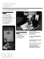
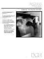
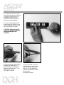
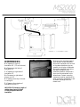
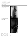
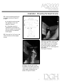
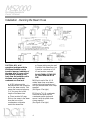
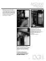
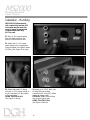
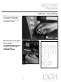
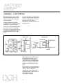
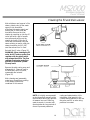
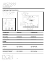
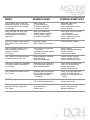
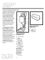
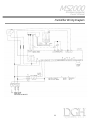
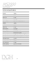
MS2000
Electronic Steam
Humidifiers
MiniSteam
Residential
Owner’s
Manual
Read and Save
these Instructions
CONTENTS
Item Page
Your MiniSteam steam humidifier will consist of:
1
INSTALLATION
MOUNTING THE HUMIDIFIER
MOUNTING THE STEAM NOZZLE
RUNNING THE STEAM HOSE.
PLUMBING
POWER WIRING
CONTROL WIRING
2
2
6
7
9
10
11
START UP AND CHECK OUT OF THE SD 2000 HUMIDIFIER
Startup Checklist
Startup Procedures
13
13
13
OPERATING YOUR MINISTEAM HUMIDIFIER
The MiniSteam Controller
The Main Control Board
14
15
16
MAINTENANCE
Cleaning the steam cylinder
Cleaning the fill and drain valves
17
17
18
ALARMS & FAULT CONDITIONS
Other Trouble-Shooting Hints
19
21
REPLACEMENT PARTS - BLOWER UNIT
21
REPLACEMENT PARTS - HUMIDIFIER UNIT
21
HUMIDIFIER WIRING DIAGRAM
22
TECHNICAL SPECIFICATIONS
23
Limited Warranty
All Products manufactured by DGH Systems, L.L.C. are warranted to the original purchaser to be free
from defects in materials and workmanship in the course of normal and reasonable use for a period of 2
years from the date of installation or 2 years and 1 month from the date of shipment, whichever comes first,
so long as the product has been installed and operated in accordance with all appropriate manuals and
wiring diagrams.
Any product or part that is found to be defective will, at the option of DGH Systems, L.L.C. be
replaced or repaired. DGH Systems, L.L.C. reserves the right to inspect any part or installation before
replacing or repairing defective parts. After startup of the product, labor for repairs or replacement of parts is
not covered by this warranty. Replacement of routinely replaceable parts such steam cylinders and gaskets
are not covered by this warranty.
DGH Systems, L.L.C. assumes no liability for consequential or inconsequential damage, or damage
due to negligence or improper use. Under the terms of this warranty, the original purchaser may have certain
legal rights and other rights which may vary from state to state.
1
Systems, L.L.C.
MS2000
MiniSteam Residential
Owner’s Manual
Your MiniSteam steam humidifier will consist of:
For duct mounted applications
(Figure 1):
■
■
■
■
■
■
■
■
■
■
■
1 Steam humidifier unit
1 Duct steam nozzle
10’ - 7/8” ID steam hose
2 Steam hose clamps
10’ - 5/16” ID condensate hose
1 Condensate hose clamp
1 HC-101 humidistat
1 PC-301 air proving switch
2 Fill cup extenders
3 Screws and anchors
1 Fill connector
Figure 1
For room mounted applications
(Figure 2):
1 Steam humidifier unit with
blower attached
■ 1 HC-101 humidistat
■ 3 Screws and anchors
■ 1 Fill connector
■
IMPORTANT:
BEFORE beginning
installation:
■ Check for shipping damage to
cartons. Mark the shipping waybill
accordingly.
■ Open cartons and check for any
hidden damage. Mark the shipping
waybill accordingly.
■ Check packing slip to insure all
items have been received. Notify
DGH immediately of any
shortages or damaged parts. You
must notify DGH within 5
working days of any shortages.
Figure 2
Systems, L.L.C.
2
MS2000
MiniSteam Residential
Owner’s Manual
Installation - Mounting the Humidifier
1. Open the carton and carefully
remove the humidifier and
accessories.
2. Open the humidifier, using a flat
blade screwdriver, and remove the
mounting hardware and
accessories.
3. Remove the plastic steam
cylinder by loosening the clamp
on the top left of the cylinder and
lifting the cylinder while twisting it
up out of its base.
a. Disconnect the wires on
top by carefully loosening and
removing the plastic knobs
holding them in place.
Carefully use a pliers if
necessary to loosen the knobs.
CAUTION: Do not squeeze
the pliers too hard, and turn
counter-clockwise only.
Figure 3
3
Systems, L.L.C.
MS2000
MiniSteam Residential
Owner’s Manual
4. Locate where you will install
the duct steam nozzle in the duct
(if used), and then decide on a
convenient location for the
humidifier, that will permit the
hoses to be sloped properly.
5. Use the mounting bracket to
mark the wall for drilling. Use a
level to insure the unit will hang
level. (See Figure 4 at right)
CAUTION: make sure that the
screws will go into wall studs to
support the weight of the
humidifier.
Figure 4
Figure 5
Figure 6
6. If the mounting screws will be
screwed into wood, drill 2 -1/8"
pilot holes for the mounting
bracket. If dry wall, drill 2 -5/16"
holes for the anchors.
(See Figure 5 above)
7. Insert the screw anchors if
needed and then screw in the
mounting screws through the
bracket. The top edge of the
bracket should stand out away
from the wall.
(See Figure 6 above)
Systems, L.L.C.
4
MS2000
MiniSteam Residential
Owner’s Manual
Figure 7
9. Remove the mounting bracket
from the back of the humidifier
Mount the humidifier unit as close
to the steam distributor pipe as
possible to minimize condensate.
Mount the humidifier unit below
the steam distributor pipe
whenever possible. Insure that a
slope can be maintained in the
steam hoses. Certain mounting
clearances must be maintained to
allow access for maintenance, and
for steam discharge from the
blower unit:
DIMENSIONS:
A =Clearance in front of
humidifier 36" (72" with blower)
B =Clearance to left side of
humidifier 12"
C =Clearance to right side of
humidifier 12"
D =Clearance to right side of
blower unit 12"
E =Clearance from top of blower
to ceiling 24"
F =Clearance from bottom of
humidifier to floor 12"
Figure 8
IMPORTANT: Maximum length of
rubber steam hose is 20 feet.
10 feet is supplied with the
humidifier.
5
Systems, L.L.C.
MS2000
MiniSteam Residential
Owner’s Manual
10. Hang the humidifier unit
carefully on the mounting bracket.
(See Figure 9 at right)
Figure 9
11. Secure the bottom of the
humidifier unit to the wall using
the third screw.
(See Figure 10 at right)
Figure 10
Systems, L.L.C.
6
MS2000
MiniSteam Residential
Owner’s Manual
Installation - Mounting the Steam Nozzle
12. Locate a suitable position for
the steam nozzle per Figure 11
at right.
a. Locate the nozzle at least
18" upstream of any duct
takeoffs or elbows.
b. If the steam nozzle is
installed from the bottom of
the duct, locate it in the center,
and cap off the condensate
outlet nipple.
12. Cut or drill a 2-1/2" hole in the
side of the duct to fit the steam
nozzle.
Figure 11
Figure 13
14. Attach the steam nozzle to the
duct using #10 by 1/2" drill point
sheet metal screws (not included).
Be sure the nozzle is mounted
level, with the 5/16" outlet nipple at
the bottom.
(See Figure 13 above)
Figure 12
13. Apply silicone caulk to the
faceplate of the steam nozzle and
insert it into the duct with the 5/16"
outlet nipple at the bottom, as
shown in Figure 12 above.
7
Systems, L.L.C.
MS2000
MiniSteam Residential
Owner’s Manual
Installation - Running the Steam Hose
Figure 14
CAUTION: 90% of all
operational problems with the
MiniSteam humidifier can be
traced to improper installation of
the steam hose. It is very critical
that steam be allowed to flow
freely from the humidifier unit to
the steam nozzle, and that
condensate can flow back.
A 20% slope must be
maintained from the humidifier
unit to the steam nozzle. That
means the hose must slope up
2 1/2" for every foot of the
length of the steam hose.
■
■ There must be NO sags,
kinks or low areas in the steam
hose that can collect
condensate or otherwise
restrict the steam flow.
Systems, L.L.C.
■ Copper tubing may be used
in place of the steam hose, but
it must be a minimum of 7/8"
ID and must be insulated.
DO NOT REDUCE THE SIZE
OF THE STEAM HOSE OR
PIPE.
16. Slip the end of the 7/8" ID
rubber steam hose over steam
nozzle inlet nipple and secure it
with the stainless steel hose clamp
supplied.
(See Figure 15 at right)
17. Slip the 5/16" ID condensate
hose over the steam nozzle
condensate outlet nipple and
secure it with the plastic hose
clamp supplied.
(See Figure 16 at right)
8
Figure 15
Figure 16
MS2000
MiniSteam Residential
Owner’s Manual
18. Bring the end of the steam
hose through the hole in the top of
the humidifier cabinet and slip the
end over the steam cylinder outlet.
Secure the hose using the stainless
the steel hose clamp supplied.
(See Figure 17 at right)
Figure 17
Figure 19
20. Bring the end of the
condensate hose through the
smaller hole in the top of the
humidifier cabinet and cut it so it
ends in the drain pan of the
humidifier.
(See Figure 19 above)
Figure 18
18. Reinstall the steam cylinder
into the humidifier unit by pressing
it down into the O-ring fitting at
the bottom, and then securing all
wires.
CAUTION: Loose electrical
connections could cause fire, so
make sure all fittings are tight.
(See Figure 18 above)
9
Systems, L.L.C.
MS2000
MiniSteam Residential
Owner’s Manual
Installation - Plumbing
IMPORTANT: Softened water
with conductivity less than 250
micromhos may be used. Raw
water is always recommended.
Demineralized water may
NOT be used.
21. Run 1/4" OD copper tubing
from the water source to the
bottom of the humidifier unit.
22. Attach the 1/4" OD copper
water tubing to the compression
fitting mounted in the plastic water
fill fitting. (See Figure 20 at right)
Figure 20
Figure 21
Figure 22
23. Attach the plastic fill fitting,
with the 1/4" OD copper tubing, to
the fill connection on the bottom
of the humidifier.
HAND TIGHTEN ONLY!
(See Figure 21 above)
24. Attach a 3/4" CPVC drain line
to drain fitting on bottom
humidifier unit, using PVC thread
sealant to insure a seal.
USE ONLY CPVC. Metal fittings
may crack the drain pan.
HAND TIGHTEN ONLY.
(See Figure 22 above)
Systems, L.L.C.
10
MS2000
MiniSteam Residential
Owner’s Manual
Installation - Power Wiring
25. Feed power wires through one
of the electrical inlets located
on the bottom of the humidifier
unit, and tighten the strain relief.
(See Figure 23 at right)
26. Insert the wires into the proper
power wiring terminals and tighten
all wires carefully.
Figure 23
CAUTION: loose wires can cause
fires. Make sure power supply
matches unit label.
(See Figure 24 at right)
Figure 24
11
Systems, L.L.C.
MS2000
MiniSteam Residential
Owner’s Manual
Installation - Control Wiring
27. Mounting the airflow switch:
Mount the airflow switch in the
supply or return duct using the
screws supplied.
Mount the device so that the
diaphragm is in a vertical position
as shown in Figure 25 below.
Put no more than 2" of tubing into
the duct. Caulk around the tubing
where it enters the duct. The low
pressure tap is left open to
atmosphere. Reverse the taps if on
the return duct.
Drill a 7/16" hole in the side of the
duct and connect the supplied
tubing to the high pressure tap on
the airflow switch and then run it
through the drilled hole in the
duct.
Figure 25
28. Mounting the On/Off control
humidistat: mount the control
humidistat to an inside wall or
post in the area to be humidified.
Position it so that no drafts from
registers or outlets are blowing
on it.
Be sure that it is not placed over a
device that could generate heat or
vapor ie: stove, machinery,
cleaning vat. If an optional duct
humidity sensor is used, mount it
to the return duct only.
(See Figure 25 above)
Systems, L.L.C.
12
MS2000
MiniSteam Residential
Owner’s Manual
29. Run control wiring from the
humidistat and air flow switch, to
the humidifier unit and enter one
of the electrical connection fittings
on the bottom of the humidifier
unit.
30. Tighten the strain relief
connector around the wires.
31. Connect the wires per one of
the following control wiring
diagrams, directly to the bottom of
the circuit board. Figure 26 is the
standard wiring diagram. If you
desire for the humidifier to
activate the heating fan whenever
there is a call for humidity, then
use the following control wiring
scheme instead. A small, 24 Vac
DPST relay will be needed.
(See Figure 27 below left)
Figure 26
Figure 27
13
Systems, L.L.C.
MS2000
MiniSteam Residential
Owner’s Manual
Start up and Check out of the SD 2000 Humidifier
Startup Checklist:
❑ 1. Water and drain lines are
connected properly. Fittings are
tight.
❑ 2. All power connections,
including internal ones, have been
checked to insure tightness.
❑
3. Wires to the electrodes on
top of the cylinder are tight.
❑ 4. Steam and condensate
hoses are properly installed and
supported to prevent sags. Hose
clamps are tight.
❑ 5. Humidistat and air flow
switch are connected per the
instructions.
Startup Procedures:
1. Turn on water to the humidifier
and check for leaks in the piping.
2. With the humidifier On/Off
switch in the OFF position, turn on
power to the humidifier.
3. Set the humidifier On/Off
switch to the ON position.
4. Set the humidistat setpoint
above the room humidity.
Filling should stop when either the
proper amperage is reached, or the
cylinder is full of water. After a
few minutes, water should start to
boil and steam should be
produced.
Startup with low conductivity
water: When the water
conductivity is less than 100
micromhos, there is not enough
conductance in the water for the
humidifier to reach even low
capacity. In this case, the
humidifier will fill completely full,
but after 10 minutes it will still not
reach a boil. In this case it is
necessary to “jump start” the
humidifier. Do this by turning the
unit off, removing the hose from
the top of the cylinder and drop in
a teaspoon full of salt or two AlkaSeltzer to raise the water
conductivity. Once the unit is
brought to a boil, it will be able to
automatically take care of
maintaining the proper mineral
concentration. If the humidifier
loses output again within a few
hours, contact the factory for a
special low conductivity adapter
system.
DO NOT USE
DEMINERALIZED WATER.
5. After the ON LED lights up,
the FILL LED should light up 15
seconds later, and the unit should
open the fill valve and begin to fill
with water.
Systems, L.L.C.
14
MS2000
MiniSteam Residential
Owner’s Manual
Operating your MiniSteam Humidifier
Sequence of Operation. (Figure
28) On a call for humidification,
the controller (R) will activate the
power contactor (A) in the
humidifier to put power to the
electrodes in the steam generating
cylinder (B). After a few seconds,
the fill valve (C) will be activated
for a minimum of several seconds
to admit water to the fill cup (V)
and read the conductivity (T). The
fill valve will remain open until
either the desired amperage draw
is reached or the water level
reaches the cylinder full probes
(E). Boiling will begin and steam
will flow to the duct distributor
pipes or to the Room Distribution
Unit. As water is boiled into
steam, the water level will reduce,
and so will the amperage draw.
When the amperage draw falls
below the required level, the fill
valve (C) will be opened and
water will be admitted to the
cylinder to increase the amperage
draw to the required level.
Periodically, based on the water
conductivity and the rate of
boiling, the controller will activate
the drain valve (S) for a short
period of time to drain some of the
mineral laden water away (S),
followed by activation of the fill
valve (C) to replenish and dilute
the water in the steam generating
cylinder.
Figure 28
15
Systems, L.L.C.
MS2000
MiniSteam Residential
Owner’s Manual
The MiniSteam Controller
Your MiniSteam humidifier has
one of the most advanced
controllers of any humidifier. It
automatically controls drain and
fill rates for the most efficient
operation possible.
The front of the controller provides
a graphic to show unit operation,
and three buttons to control
functions.
Setting Maximum Steam Output:
Press the UP key (#2 fig 29) until
the appropriate LED on the output
graph lights up. Once for 30%,
two times for 50%, three times for
75%, and four times for 100%.
This setting can be used to reduce
the output of the humidifier for
applications where the full output
may not be needed.
Figure 29
The controller parts are:
1. RESET button to reset alarms. When an alarm
occurs, the LEDs will blink in a certain way (see the
trouble-shooting section of this manual), and the
RESET button will glow red.
2. Increase capacity button. Pressing this button
increases the capacity of the humidifier in
increments.
3. DRAIN button for manual drain selection.
Push and hold to force the unit to drain all water.
4. 30% steam output level indicator.
5. 50% steam output level indicator.
6. 75% steam output level indicator.
7. 100% steam output level indicator.
8. Unit humidifying indicator.
9. High water level indicator.
10. Unit filling indicator.
11. Unit draining indicator.
Systems, L.L.C.
16
MS2000
MiniSteam Residential
Owner’s Manual
The Main Control Board
Inside your MiniSteam humidifier
is the main control board. It has
similar functions to the keypad on
the front of the unit.
Figure 30
Setting Maximum Steam Output:
Press the UP key until the
appropriate LED on the output
graph lights up. Once for 30%,
two times for 50%, three times for
75%, and four times for 100%.
This setting can be used to reduce
the output of the humidifier for
applications where the full output
may not be needed.
1. Connector for the front keypad
16. Dehumidify indicator.
2. RESET button
17. Alarm indicator.
3. DRAIN button for manual draining
18. Unit draining indicator.
4. UP button to increase capacity
19. Unit filling indicator.
5. Serial connection for “smart homes”
20. Microprocessor.
6. Amperage transformer
21. Conductivity adjustment.
7. 30% steam output level indicator.
22. Terminal connectors.
8. 50% steam output level indicator.
9. 75% steam output level indicator.
10. 100% steam output level indicator.
11. DIP switches to select signal input.
12. Configuration EEPROM.
13. Power relay.
14. Unit humidifying indicator.
15. High water level indicator.
17
Systems, L.L.C.
MS2000
MiniSteam Residential
Owner’s Manual
Maintenance
Although your MiniSteam
humidifier is designed to take care
of its normal operation, and even
to provide you with diagnostic
capability, good operation always
means good maintenance.
Periodic cleaning or replacement
of the steam generating cylinder,
and cleaning of the fill and drain
valves is required as indicated by
the controller with a “worn out
cylinder alarm.
Also, at the end of each
humidification season, it is good
practice to shut off the humidifier
and manually drain the cylinder of
water to prevent premature rusting
and corrosion of the electrodes
during the nonuse season.
Cleaning the steam
cylinder:
1. Drain the steam cylinder of all
water by pressing and holding the
DRAIN button on the controller
until the cylinder is completely
empty.
2. Shut off the humidifier with the
On/Off switch on the front, and
disconnect power to the unit at the
external fused disconnect.
CAUTION: If you have a blower
unit, there may be more than one
disconnect.
3. Loosen the hose clamp around
the steam hose on top of the steam
cylinder and remove the hose.
Loosen the steam cylinder holddown clamp.
4. Remove the power wires on
the top of the steam cylinder and
also the red cylinder full probe
connectors, and lift the steam
cylinder straight up out of the
drain fitting, and then out of the
humidifier.
5. To clean the cylinder, wash out
all heavy mineral by inverting the
cylinder and flushing water
through the bottom drain outlet.
Then fill the cylinder with either a
5% phosphoric acid solution
(humidifier cleaner), or a 50%
solution of Lime-Away . If the
electrodes are too badly corroded,
replace the entire steam cylinder.
Systems, L.L.C.
18
6. Reinstall the cylinder in the
humidifier unit and connect all
wires, being sure to get them tight.
CAUTION: loose cylinder wires
can become hot and melt the
cylinder or cause fires.
MS2000
MiniSteam Residential
Owner’s Manual
Cleaning the fill and drain valves:
After shutdown and removal of the
steam cylinder, shut off the water
supply to the humidifier,
disconnect the water supply and
remove the fill valve from the
humidifier. Remove the inlet
strainer by reaching up into the fill
valve inlet with a pair of needle
nose pliers and pulling out the
strainer by its tab. Clean the fill
valve and inlet strainer using the
same solution as used to clean the
steam humidifier, but DO NOT
soak the solenoid coil in fluid.
Reinstall the fill valve. (Figure 31)
WARNING: When cleaning the fill
valve, do NOT poke or probe flow
regulator with any object which
may enlarge the orifice. The flow
regulator must meter water flow
precisely or shortened cylinder
life may result.
Figure 31
Remove the drain valve group and
disassemble it. Clean all parts in
the same way as the fill valve,
reassemble and reinstall.
(Figure 32)
After cleaning and reassembly,
restart your humidifier according
to the Startup Instructions
contained in this manual.
Figure 32
NOTE: It is highly recommended
to shut down and manually drain
the humidifier during any periods
of seasonal non-use. Allowing
water to remain in contact with
the electrodes for long periods of
time will promote premature
19
rusting and deterioration of the
electrodes. Algal growth in the
cylinder during periods of non-use
may also result in an odor being
produced on restart.
Systems, L.L.C.
MS2000
MiniSteam Residential
Owner’s Manual
Alarms and Fault Conditions
When an alarm appears, it must
be cleared by pressing the RESET
button on the controller. If the
alarm condition still exists, the
alarm will continue.
Figure 33
Figure 34
DEFINITION
FACE PAD
CONTROLLER
Lack of water
LED #7 blinks
LED #18 blinks
Faulty drainage
LED #8 blinks
LED #19 blinks
Worn out cylinder
LED #6 blinks
LED #15 blinks
Lack of current
LED #5 blinks
LED #14 blinks
High current
LEDs #1-2-3-4 blink
LEDs #7-8-9-10 blink
Data error
LEDs #3-4 blink
LEDs #9-10 blink
Faulty sensor
LEDs #2-3-4 blink
LEDs #8-9-10 blink
EEPROM configuration error
LEDs #1-2 blink
LEDs #7-8 blink
Power supply of controller
LEDs #1-4 blink
LEDs #7-10 blink
PRE-ALARMS
ALARMS
Systems, L.L.C.
20
MS2000
MiniSteam Residential
Owner’s Manual
ERROR
POSSIBLE CAUSES
POSSIBLE CORRECTIONS
Lack of water: the fill valve has
remained energized for more than
20 minutes without any increase
in amperage
-
water turned off
fill valve obstructed
fill strainer obstructed
no power to fill valve
-
Faulty drainage: the drain valve
remains open for more than 2
minutes without a decrease in
water level
-
drain valve obstructed
mineral bridge in cylinder
cylinder screen clogged
no power to drain valve
- check drain valve and screen
for obstruction
- clean or replace cylinder
- check wires/power to valve
- replace drain valve
Worn out cylinder: output has not
risen above 50% in more than 72
hours
- electrodes coated
- drain screen full of mineral
- clean or replace cylinder
Lack of current: cylinder is full of
water and there has been no
current for at least
20 minutes
- one or more electrodes has
lost power
- amperage transformer broken
- contactor broken
-
High current: the current exceeds
the safety threshold by 170%
- mineral bridge on electrode
- leaking fill valve
- drain valve obstructed
- clean or replace cylinder
- clean or replace fill valve
- clean or replace drain valve
Data error: conductivity, amperage
or humidity sensor input value is
out of range
- loose/bad wiring connection
- DIP switches set improperly
- faulty humidity sensor
-
Faulty sensor: the sensors value is
out of range
- loose/bad wiring connection
- DIP switches set improperly
- sensor broken or needs
calibration
- check all wiring connections
- check DIP switch settings
- replace or recalibrate humidity
sensor
EEPROM configuration error:
- main board programmed wrong
- DIP switches set improperly
- check DIP switch settings
- replace main board
Power supply of controller: the
secondary 24 Vac voltage falls
10% below
- reduction of incoming power
- faulty transformer
- internal short
- check incoming voltage
- check wiring for shorts
- replace transformer
21
make sure water is on
clean fill strainer
check wires/power to valve
replace fill valve
check all fuses
replace amperage transformer
replace contactor
check external power
check all wiring connections
check DIP switch settings
replace main board
replace humidity sensor
Systems, L.L.C.
MS2000
MiniSteam Residential
Owner’s Manual
Other Trouble-Shooting Hints:
1. The water in the cylinder turns
black: This is usually an indication
that the minerals in the cylinder
have over-concentrated and the
pH of the water has dropped
causing a deterioration of the
electrodes. Left unchecked, this
will lead to a very short cylinder
life. Check for low spots or kinks
in the steam hoses that could
cause a back pressure on the
cylinder. Check the duct static
pressure. Check the fill valve and
inlet strainer. Check the drain
valve operation. Contact the
factory.
2. Heavy arcing occurs within
hours of startup: The feed water
contains large amounts of Iron,
Copper or other conductive
contaminants. Contact the factory
for an optional drain timer to force
additional drains to control the
minerals. If you are using a
softener, check the salt being used.
If it contains any additives,
discontinue use, flush all lines and
convert to pure salt or pipe raw,
unsoftened water to the humidifier.
It is usually best NOT to use
softened water. Check the
electrodes in the cylinder to be
sure they were not damaged in
shipping.
Systems, L.L.C.
Figure 36
Replacement Parts Blower Unit
Figure 35
Replacement Parts Humidifier Unit
1: Hose snap clamp
2: Steam hose
SH75
3: Rubber pipe
1312345AXX
4: Steam cylinder
L200MA
5: Cylinder O-ring
6: Fill valve kit
9995642ACA
7,8:
Drain valve kit
KITVSCOMP0
9: Bottom tank
18: C344A004
10: Hose snap clamp
11: Rubber pipe
13: 12348AXX
12: Rubber pipe
13: 12345AXX
13: Fill cup
13C119A003
22
1: Ventilator unit
VRDC
2: Remote base
VRDC BASE
MS2000
MiniSteam Residential
Owner’s Manual
Humidifier Wiring Diagram
23
Systems, L.L.C.
MS2000
MiniSteam Residential
Owner’s Manual
Technical Specifications
Capacity:
7 lbs/hr
Voltage:
220/1/60
Amperage:
10.6 Amps
Power Use:
2.2 kW
Water Pressure:
15-100 psi
Conductivity:
125-1250 micromhos
Shipping Weight:
TECHNICAL SPECIFICATIONS
Capacity:
7 lbs/hr
Voltage:
220/1/60
Amperage:
10.6 Amps
Power Use:
2.2 kW
Water Pressure:
15-100 psi
Conductivity:
125-1250 micromhos
Shipping Weight:
RD103CL220 = 45 lbs.
RF103CL220 = 50 lbs.
Dimensional data:
14 3/4" High X 11" Wide X 7 1/2" Deep
Steam Nozzle:
High temperature fibreglas
Steam Hose:
Non-conductive, high temperature silicone
Feed Water Temp:
<= 120 F
Feed Water Connection:
1/4"
OD compression
Drain Water Connection:
3/4"
FPT
Max. Water Use:
1.2 gph
Blower Capacity:
317 CFM, 38.5 dBNR
Blower Power Use:
20 Watts
Systems, L.L.C.
24
MS2000
MiniSteam Residential
Owner’s Manual
For more information call
1-800-DGH-4649
1834 Freedom Road,
Lancaster, PA 17601
Tel: (717) 293-5210
Fax: (717) 293-0449
Internet: http://www.dghsys.com
Systems, L.L.C.
Leadership in Humidification
© 1997 by DGH Systems, L.L.C. All rights reserved
Form # 97-98 Printed in U.S.A.