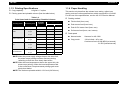
1
6(59,&( 0$18
18$
$/
Impact Serial Dot Matrix Printer
EPSON LQ-2180
®
SEDM98001
Notice:
„ All rights reserved. No part of this manual may be reproduced, stored in a retrieval system, or transmitted in any form or by any means,
electronic, mechanical, photocopying, recording, or otherwise, without the prior written permission of SEIKO EPSON CORPORATION.
„ The contents of this manual are subject to change without notice.
„ All effort have been made to ensure the accuracy of the contents of this manual. However, should any errors be detected, SEIKO EPSON
would greatly appreciate being informed of them.
„ The above not withstanding SEIKO EPSON CORPORATION can assume no responsibility for any errors in this manual or the consequences
thereof.
EPSON is a registered trademark of SEIKO EPSON CORPORATION.
General Notice:
Other product names used herein are for identification purpose only and may be trademarks or registered trademarks of their
respective owners. EPSON disclaims any and all rights in those marks.
Copyright © 1996 SEIKO EPSON CORPORATION. Printed in Japan.
PRECAUTIONS
Precautionary notations throughout the text are categorized relative to 1)Personal injury and 2) damage to equipment.
DANGER
Signals a precaution which, if ignored, could result in serious or fatal personal injury. Great caution should be exercised in
performing procedures preceded by DANGER Headings.
WARNING
Signals a precaution which, if ignored, could result in damage to equipment.
The precautionary measures itemized below should always be observed when performing repair/maintenance procedures.
DANGER
1. ALWAYS DISCONNECT THE PRODUCT FROM THE POWER SOURCE AND PERIPHERAL DEVICES PERFORMING ANY MAINTENANCE
OR REPAIR PROCEDURES.
2. NOWORK SHOULD BE PERFORMED ON THE UNIT BY PERSONS UNFAMILIAR WITH BASIC SAFETY MEASURES AS DICTATED FOR
ALL ELECTRONICS TECHNICIANS IN THEIR LINE OF WORK.
3. WHEN PERFORMING TESTING AS DICTATED WITHIN THIS MANUAL, DO NOT CONNECT THE UNIT TO A POWER SOURCE UNTIL
INSTRUCTED TO DO SO. WHEN THE POWER SUPPLY CABLE MUST BE CONNECTED, USE EXTREME CAUTION IN WORKING ON
POWER SUPPLY AND OTHER ELECTRONIC COMPONENTS.
WARNING
1. REPAIRS ON EPSON PRODUCT SHOULD BE PERFORMED ONLY BY AN EPSON CERTIFIED REPAIR TECHNICIAN.
2. MAKE CERTAIN THAT THE SOURCE VOLTAGES IS THE SAME AS THE RATED VOLTAGE, LISTED ON THE SERIAL NUMBER/RATING
PLATE. IF THE EPSON PRODUCT HAS A PRIMARY AC RATING DIFFERENT FROM AVAILABLE POWER SOURCE, DO NOT CONNECT IT
TO THE POWER SOURCE.
3. ALWAYS VERIFY THAT THE EPSON PRODUCT HAS BEEN DISCONNECTED FROM THE POWER SOURCE BEFORE REMOVING OR
REPLACING PRINTED CIRCUIT BOARDS AND/OR INDIVIDUAL CHIPS.
4. IN ORDER TO PROTECT SENSITIVE MICROPROCESSORS AND CIRCUITRY, USE STATIC DISCHARGE EQUIPMENT, SUCH AS ANTISTATIC WRIST STRAPS, WHEN ACCESSING INTERNAL COMPONENTS.
5. REPLACE MALFUNCTIONING COMPONENTS ONLY WITH THOSE COMPONENTS BY THE MANUFACTURE; INTRODUCTION OF
SECOND-SOURCE ICs OR OTHER NONAPPROVED COMPONENTS MAY DAMAGE THE PRODUCT AND VOID ANY APPLICABLE EPSON
WARRANTY.
PREFACE
This manual describes basic functions, theory of electrical and mechanical operations, maintenance and repair
instructions and procedures included herein are intended for the experienced repair technicians, and attention
the preceding page. The chapters are organized as follows:
CHAPTER 1.
PRODUCT DESCRIPTIONS
Provides a general overview and specifications of the product.
CHAPTER 2.
OPERATING PRINCIPLES
Describes the theory of electrical and mechanical operations of the produc
CHAPTER 3.
DISASSEMBLY AND ASSEMBLY
Describes the step-by-step procedures for disassembling and assembling th
product.
CHAPTER 4.
ADJUSTMENTS
Provides Epson-approved methods for adjustment.
CHAPTER 5.
TROUBLESHOOTING
Provides the step-by-step procedures for troubleshooting.
CHAPTER 6.
MAINTENANCE
Provides preventive maintenance procedures and the lists of Epson-approv
lubricants and adhesives required for servicing the product.
APPENDIX
Provides the following additional information for reference:
• EEPROM Address Map
• Connector Pin Assignments
• C272 Main Board Component Layout
• C272 Main Board Circuit Diagram
Revision Status
Revision
Issued Date
Description
A
February 3, 1999
First Release
Contents
Product Description
Specifications ................................................................................................. 8
Features ................................................................................................................ 8
Accessories ........................................................................................................... 8
Printing Specifications ........................................................................................... 9
Paper Handling ...................................................................................................... 9
Paper Specifications ............................................................................................ 11
Electrical Specifications ....................................................................................... 15
Reliability ............................................................................................................. 15
Safety Approvals ................................................................................................. 15
CE Marking .......................................................................................................... 15
Firmware Specifications ............................................................................... 16
Control Codes and Fonts .................................................................................... 16
Interface Specifications ....................................................................................... 18
Disassembly and Assembly
Adjustment
Overview ...................................................................................................... 33
Pre-operation for the Adjustment Program ......................................................... 33
Bi-D Adjustment .................................................................................................. 35
TPE Level Reset ................................................................................................. 36
Writing the User-characteristic Data ................................................................... 37
Troubleshooting
Control Panel ....................................................................................................... 19
Bi-directional Adjustment Function ...................................................................... 19
EEPROM Initialization ......................................................................................... 20
Main Components ......................................................................................... 21
C272MAIN Board ................................................................................................ 22
Printer Mechanism .............................................................................................. 23
Overview ...................................................................................................... 40
Troubleshooting Information ........................................................................ 40
Printhead ............................................................................................................. 40
Sensors ............................................................................................................... 40
Motors ................................................................................................................. 40
Error Codes with Indicators and Buzzer .............................................................. 40
Unit Level Troubleshooting ........................................................................... 41
Repairing the C165 PSB/PSE Board .............................................................. 41
Repairing the C272MAIN Board ..................................................................... 41
Repairing the Printer Mechanism .................................................................. 43
Operating Principles
Maintenance
Parallel Interface (Forward Channel) .................................................. 18
Parallel Interface (Reverse Channel) ................................................. 18
Operation Instruction .................................................................................... 19
Control Circuit .............................................................................................. 25
Overview of the Control Circuit Operation ........................................................... 25
System Reset Circuit ........................................................................................... 26
Printhead Driver Circuit ....................................................................................... 27
CR Motor Driver Circuit ....................................................................................... 28
PF Motor Driver Circuit ........................................................................................ 28
EEPROM Control Circuit ..................................................................................... 29
Sensor Circuit ...................................................................................................... 29
Appendix
EEPROM Address Map .................................................................................
Connector Summary .....................................................................................
Component Layout .......................................................................................
Circuit Diagram ............................................................................................
47
51
53
55
PRODUCT DESCRIPTION
LQ-2180
Revision A
1.1 Specifications
1.1.2 Accessories
The LQ-2180 is a revised model of the already existing LQ-2170. Since
the specifications for the both products are mostly common except for
the LQ-2180’s improved features such as printing speed and copy
capability, the information included in this section is limited to the items
that are specific to LQ-2180. For the rest of the information, refer to the
LQ-2170 Service Manual.
1.1.1 Features
† Printing speed
„ High speed draft:
480 cps
„ Draft:
360 cps
„ LQ:
120 cps (at 10 cpi)
† Character tables
„ Standard version:
13 tables
„ NLSP version:
38 tables
† Items included in the printer carton
Table 1-1. Items Included in the Printer
Items
User’s manual
1
Driver disk
1
Ribbon cartridge
1
Power supply cable (230 V version)
1
† Consumable items
Table 1-2. Items Included in the Printer
Items
† Bi-directional Interface
S015086
Ribbon pack
S010033
† Optional items: Additional items are shown in the table below:
Table 1-3. Items Included in the Printer
Items
„ 1 original + 5 copies
Product Description
Part Number
IEEE-1284 parallel I/F card
C82345∗
Ethernet I/F card
C82357∗ / C82362∗ / C82363∗ /
C82363∗ (See NOTE below.) /
C82364∗
„ Optional Type-B I/F Level 2 supported
† Copy capability
Part Number
Ribbon cartridge
† Reliability
„ Mean print volume between failure: 23 million lines
(except printhead)
Quantity
NOTE: When you use Ethernet interface card C82363∗, you
need to attach the optional interface adapter (C82525*)
to the interface card.
Specifications
8
LQ-2180
Revision A
1.1.3 Printing Specifications
† Copy capability:
1.1.4 Paper Handling
1 original + 5 copies
This section only describes the release lever setting, adjust lever
setting, and some other specifications which are specific to LQ-2180.
For the rest of the specifications, see the LQ-2170 Service Manual.
† Printing speed and printable column (See the table below.)
Table 1-4.
Print Speed and Corresponding Printable Columns
Printing mode
Character pitch
High speed draft
Draft
Printable
columns
† Feeding method
Printing speed (cps)
„ Friction feed (front, rear)
Normal
Copy
„ Push tractor feed (front lever)
10 cpi
136
480
320
„ Push & Pull tractor feed (front, rear)
10 cpi
136
360
240
„ Pull tractor feed (front, rear, bottom)
12 cpi
163
431
286
15 cpi
204
539
358
17 cpi
233
308
205
20 cpi
272
359
239
10 cpi
136
120
80
12 cpi
163
143
96
15 cpi
204
179
120
17 cpi
233
204
137
20 cpi
272
238
159
Draft condensed
LQ
† Feed speed
„ Normal mode:
Same as for LQ-2180
„ Copy mode:
1/6 inch feed = 45 m sec
Continuous feed =0.092 MPW (m/second)
3.6 IPS (inches/second)
LQ condensed
NOTE: When the power supply voltage drops to the lower limit,
the printer stops printing and then resumes printing
remaining on that line more slowly than before.
NOTE: When the head temperature rises to the upper limit, the
printer stops printing. When the head temperature falls
to the normal level, the printer starts printing again more
slowly than before.
NOTE: The maximum printable width is 13.6 inch (345.44 mm).
Product Description
Specifications
9
LQ-2180
Revision A
† Release lever:
† Adjust lever:
See the following table.
Table 1-5. Release Lever Settings
Lever Position
Paper path / Feeder
See the following table.
Table 1-6. Adjust Lever Setting Position
Paper / Media
Paper Thickness (inch)
Setting
Position
Minimum
Maximum
0
0.0024
0.0047
over 0.006 up to 0.12
1
0.0047
0.0074
over 0.12 up to 0.19
Paper Thickness (mm)
Manual insertion (front)
Cut sheet
(Single sheet & Multi part), Card
Manual insertion (rear)
Cut sheet (Single sheet & Multi part),
Card, Envelope
Cut sheet (Single sheet & Multi part),
Card, Envelops
2
0.0074
0.0102
over 0.19 up to 0.26
CSF Bin 1
3
0.0102
0.0126
over 0.26 up to 0.32
CSF Bin 2
Cut sheet (Single sheet)
4
0.0126
0.0141
over 0.32 up to 0.36
Roll paper holder
Roll paper
5
0.0141
0.0157
over 0.36 up to 0.40
Push tractor feed (front)
Continuous paper (Single sheet & Multi
part), Continuous paper with labels
6
0.0157
0.0173
over 0.40 up to 0.44
Push & Pull tractor feed
(front)
Continuous paper (Single sheet & Multi
part), Continuous paper with labels
7
0.0173
0.0181
over 0.44 up to 0.46
Push tractor feed (rear)
Continuous paper
(Single sheet & Multi part)
Push & Pull tractor feed
(rear)
Continuous paper
(Single sheet & Multi part)
Pull tractor feed (front)
Continuous paper (Single sheet & Multi
part), Continuous paper with labels
Pull tractor feed (rear)
Continuous paper
(Single sheet & Multi part)
Pull tractor feed
(bottom)
Continuous paper (Single sheet & Multi
part), Continuous paper with labels
Friction
Front tractor
Rear tractor
Full release
Product Description
Specifications
10
LQ-2180
Revision A
1.1.5 Paper Specifications
Table 1-8. Cut Sheet (Multi Part)
Front Entry
This section provides paper specifications for the LQ-2180.
Table 1-7. Cut Sheet
Front Entry
Rear Entry
Minimum
Maximum
Minimum
Maximum
Width
(inch)
(mm)
3.9
100
16.5
420
3.9
100
16.5
420
Length
(inch)
(mm)
5.8
148
16.5
420
3.9
100
16.5
420
Thickness
(inch)
(mm)
0.0025
0.065
0.0055
0.14
0.0025
0.065
0.0055
0.14
Weight
(g/m2)
(lb.)
52
14
90
24
52
14
90
24
Quality
Plain paper, Recycled paper,
Paper that is not curled,
folded, or crumpled.
Plain paper, Recycled paper,
Paper that is not curled,
folded, or crumpled.
Rear Entry
Minimum
Maximum
Minimum
Maximum
Width
(inch)
(mm)
3.9
100
16.5
420
3.9
100
16.5
420
Length
(inch)
(mm)
5.8
148
16.5
420
3.9
100
16.5
420
Copies
Total Thickness
Weight
(one sheet of multi part)
1 original + 5 copies
1 original + 5 copies
(inch)
(mm)
0.0047
0.12
0.018
0.46
0.0047
0.12
0.018
0.46
(g/m2)
(lb.)
40
12
58
15
40
12
58
15
Quality
Plain paper, Recycled paper, Paper that is not curled,
folded, or crumpled.
Jointing
Line glue at the top or one
side of form.
Line glue at the top of form.
NOTE: Printing on recycled paper is available only under normal
temperature and humidity conditions.
Product Description
Specifications
11
LQ-2180
Revision A
Table 1-9. Card
Table 1-10. Envelope
Front Entry
Rear Entry
Front Entry
Minimum
Maximum
Minimum
Maximum
(inch)
(mm)
3.9
100
7.8
200
3.9
100
7.8
200
Length
(inch)
(mm)
5.8
148
7.8
200
5.8
148
7.8
200
Thickness
(inch)
(mm)
0.0087
0.22
0.0087
0.22
(g/m2)
(lb.)
192
51
192
51
Plain paper, Recycled paper,
Paper that is not curled,
folded, or crumpled.
Plain paper, Recycled paper,
Paper that is not curled,
folded, or crumpled.
Width
Weight
Quality
Minimum
Maximum
---
6.5
165
Length
(inch)
(mm)
---
3.6
92
Width
(inch)
(mm)
---
9.5
241
Length
(inch)
(mm)
---
4.1
105
(inch)
(mm)
---
---
Total Thickness
(g/m2)
(lb.)
---
0.0063
0.16
45
12
---
NOTE: When the longer side of A6 card is horizontally, it should be
inserted from the rear entrance.
---
0.020
0.52
The difference of thickness
at the printable area is within
0.0098 inch (0.25mm).
---
Quality
Maximum
(inch)
(mm)
Envelop
(No. 10)
Weight
Minimum
Width
Envelop
(No. 6)
NOTE: Printing on recycled paper is available only under normal
temperature and humidity conditions.
Rear Entry
90
24
BOND paper, plain paper or
AIRMAIL
No glue at a flap
Not curled, not folded, not
crumpled
NOTE: Printing on envelope is available only under normal
temperature and humidity conditions.
NOTE: Envelopes should be inserted from rear entrance only.
NOTE: Set the longer side of envelope horizontally.
Product Description
Specifications
12
LQ-2180
Revision A
Table 1-11. Continuous Paper (Single sheet and Multi Part)
Front Entry
Rear Entry
Table 1-12. Continuous Paper with Labels
Bottom Entry
Min.
Max.
Min.
Max.
Min.
Max.
Front Entry
Min.
Max.
Bottom Entry
Rear Entry
Min.
Min.
Max.
Max.
Width
(inch)
(mm)
4
101.6
16
406.4
4
101.6
16
406.4
4
101.6
16
406.4
Label size
Length
(one page)
(inch)
(mm)
4
101.6
22
558.8
4
101.6
22
558.8
4
101.6
22
558.8
Base sheet width
(inch)
(mm)
4
101.6
16
406.4
4
101.6
16
406.4
---
---
Base sheet length
(one page)
(inch)
(mm)
4
101.6
22
558.8
4
101.6
22
558.8
---
---
Base sheet
thickness
(inch)
(mm)
0.0028
0.07
0.0035
0.09
0.0028
0.07
0.0035
0.09
---
---
Total thickness
(inch)
(mm)
0.0063
0.16
0.0075
0.19
0.0063
0.16
0.0075
0.19
Label weight
(g/m2)
(lb.)
1 original + 5
copies
Copies
1 original + 5
copies
1 original + 5
copies
Total
Thickness
(inch)
(mm)
0.0025
0.065
0.018
0.46
0.0025
0.065
0.018
0.46
0.0025
0.065
0.018
0.46
Weight
(not multi
part)
(g/m2)
(lb.)
52
14
82
22
52
14
82
22
52
14
82
22
Weight
(g/m2)
(one sheet
(lb.)
of multi part)
40
12
58
15
40
12
58
15
40
12
58
15
Quality
Quality
Plain paper, Recycled paper, Carbonless multi part paper
Jointing
Point glue or paper staple (both side)
See the figure
below
68
17
See the figure
below
68
17
---
---
AVERY CONTINUOUS FORM
LABELS, AVERY MINI-LINE LABELS
or the same quality labels
NOTE: Printing on labels si available only under normal temperature
and humidity condition.
NOTE: The base sheet of labels must be continuous paper.
NOTE: Continuous paper with labels should be inserted from the
front or bottom entrance.
2.5 inch (63.5 mm) min.
15/16inch
(23.8 mm)
min.
Label
R 0.1 inch (2.5 mm) min.
Figure 1-1. Printable Area - Label
Product Description
Specifications
13
LQ-2180
Revision A
Table 1-13. Roll Paper
Front Entry
Minimum
Maximum
Rear Entry
Minimum
Maximum
Width
(inch)
(mm)
---
8.5
216
Length
(inch)
(mm)
---
---
Thickness
(inch)
(mm)
---
---
0.0028
0.07
0.0035
0.09
Weight
(g/m2)
(lb.)
---
---
52.3
14
82
22
Quality
Product Description
---
Plain paper, Recycled paper,
Paper that is not curled,
folded, or crumpled.
Specifications
14
LQ-2180
Revision A
1.1.6 Electrical Specifications
The electrical specifications for the LQ-2180 is the same as for the LQ2170 except for the items below. For information on other items, see the
LQ-2170 Service Manual.
† Input voltage range
„ 120 V version:
AC 99 to 132 V
„ 230 V version:
AC 198 to 264 V
(same as for the LQ-2170
† Rated current
† 230 V version
„ Safety standards:
EN60950 (TUV)
„ EMI:
EN55022 (CISPR pub.22) class B
AS/NZS 3548 class B
1.1.9 CE Marking
† 230 V version
„ Low voltage directive 73/23/EEC:EN60950
„ 120 V version:
1.0 A (maximum = 4.0 A)
„ 230 V version:
0.5 A (maximum = 2.0 A)
„ EMD Directive 89/336/EEC:
† Power consumption (for 120 V and 230 V versions)
„ Approximately 52 W (ISO/IEC10561 Letter pattern)
(Energy Star compliant)
† Acoustic noise:
1.1.7 Reliability
† MVBF *1:
24 million lines (except print data)
† MTBF:
10000 POH
† Printhead life:
400 million strokes/wire
EN55022 class B
EN61000-3-2
EN61000-3-3
EN50082-1
IEC801-2
IEC801-3
IEC801-4
Approximately 54 db(A)
(ISO 7779 pattern)
*1: Mean print volume between failure
1.1.8 Safety Approvals
† 120 V version
„ Safety standards:
UL1950, CSA C22.2 No. 950
„ EMI:
FCC part15 subpart B class B
CSA C108.8 class B
Product Description
Specifications
15
LQ-2180
Revision A
1.2 Firmware Specifications
International character set (14 countries and legal)
This section describes the firmware specifications for the LQ-2180.
1.2.1 Control Codes and Fonts
† Control codes:
ESC/P2 and IBM 2391 Plus Emulation
† Character tables:
Standard version (13 character tables)
Italic table
PC 860 (Portuguese)
PC 850 (Multilingual)
PC 437 (US, Standard Europe)
PC 861 (Icelandic)
PC 863 (Canadian-French)
PC 865 (Nordic)
Abicomp
BRASCII
Roman 8
ISO Latin 1
PC 858
ISO 8859-15
NLSP version (38 character tables)
Italic table
PC437 (US, Standard Europe)
PC437 Greek
PC850 (Multilingual)
PC852 (East Europe) PC853 (Turkish) PC855 (Cyrillic)
PC857 (Turkish)
PC864 (Arabic)
PC866 (Russian)
PC869(Greek)
MAZOWIA (Poland)Code MJK (CSFR)
ISO 8859-7 (Latin/Greek) lSO Latin 1T (Turkish)
Bulgaria (Bulgarian) PC774 (LST 1283:1993)
Estonia (Estonia)
ISO 8859-2
PC866 LAT. (Latvian)
PC866 UKR (Ukraina)PC860 (Portuguese)
PC861 (Icelandic)
PC865 (Nordic)
PC APTEC(Arabic)
PC708 (Arabic)
PC720 (Arabic)
PCAR864 (Arabic)
PC863 (Canadian-French)
Abicomp
BRASCII
Roman 8
ISO Latin 1
Hebrew7*
Hebrew8*
PC862 (Hebrew)*
PC 858
lSO 8859-15
U.S.A.
U.K.
Italy
Norway
Latin America
France
Denmark 1
Spain 1
Denmark 2
Korea
Germany
Sweden
Japan
Spain 2
Legal
* The international and legal characters are these 12 codes:
23H, 24H, 40H, 5BH, 5CH, 5DH,
5EH, 60H, 7BH, 7CH, 7DH, 7EH
† Typeface
Bit map fonts
EPSON Draft
EPSON Roman
EPSON Sans Serif
EPSON Courier
EPSON Prestige
EPSON Script
EPSON OCR-B
EPSON Orator
EPSON Orator-S
EPSON Script C
10 CPI, 12 CPI, 15CPI
10 CPI, 12 CPI, 15CPI, Proportional
10 CPI, 12 CPI, 15CPI, Proportional
10 CPI, 12 CPI, 15CPI
10 CPI, 12 CPI
10 CPI
10 CPI
10 CPI
10 CPI
Proportional
Scalable fonts
EPSON Roman
EPSON Sans Serif
EPSON Roman T
EPSON Sans Serif H
10.5 pt., 8 pt., - 32 pt. (every 2 pt.)
10.5 pt., 8 pt., - 32 pt. (every 2 pt.)
10.5 pt., 8 pt., - 32 pt. (every 2 pt.)
10.5 pt., 8 pt., - 32 pt. (every 2 pt.)
Bar codes
EAN-13,
UPC-A
Code 128
EAN-8
UPC-E
POSTNET
Interleaved 2 of 5
Code 39
* Not displayed in the Default setting mode.
Product Description
Firmware Specifications
16
LQ-2180
Revision A
Table 1-14. Character Tables and Available Typefaces
Character Tables
table*1
Standard
version
Bit map font
Italic
PC 850 (Multilingual)*1
PC 861 (Icelandic)*1
PC 863(Canadian-French)*1
Abicomp*1
Roman 8
PC 858
PC 437 (US, Standard
PC 860 (Portuguese)*1
PC 865 (Nordic)*1
BRASCII*1
ISO Latin 1
ISO 8859-15
Italic table*1
PC 850 (Multilingual)*1
PC 861 (Icelandic)*1
PC 865(Nordic)*1
Abicomp*1
lSOLatin1
ISO 8859-15
PC 437(US, Standard Europe)*1
PC 860(Portuguese)*1
PC863 (Canadian-French)*1
BRASCIl*1
Roman8
PC 858
PC 864 (Arabic)
NLSP
version
Scaleable font
Europe)*1
PC437Greek
PC 853 (Turkish)
PC 857 (Turkish)
PC 869 (Greek)
Code MJK (CSFR)
lSO Latin 1T (Turkish)
PC774 (LST 1283: 1993)
1SO 8859-2
PC 866 UKR (Ukraina)
PC 852 (East Europe)
PC 855 (Cyrillic)
PC 866 (Russian)
MAZOWIA (Poland)
lSO 8859-7 (Latin/Greek)
Bulgaria (Bulgarian)
Estonia (Estonia)
PC 866 LAT. (Latvian)
PC APTEC (Arabic)
PC 720 (Arabic)
PC 708 (Arabic)
PCAR864 (Arabic)
Hebrew7*2
Hebrew 8*2
PC862 (Hebrew)*2
EPSON Draft
EPSON Roman
EPSON Sans Serif
EPSON Courier
EPSON Prestige
EPSON Script
EPSON OCR-B
EPSON Orator
EPSON Orator-S
EPSON Script C
EPSON Roman
EPSON Sans Serif
EPSON Roman T
EPSON Sans Serif H
EPSON Draft
EPSON Roman
(Not supported)
EPSON Draft
EPSON Roman
EPSON Sans Serif
EPSON Courier
EPSON Prestige
EPSON Script
(Not supported)
EPSON Draft (Arabic)
EPSON Roman
EPSON Sans Serif
(Not supported)
EPSON Draft (Hebrew)
EPSON Roman
(Not supported)
EPSON Courier
*1: ESC R command is effective on these character tables.
*2 Not displayed in the default setting mode.
Product Description
Firmware Specifications
17
LQ-2180
Revision A
1.2.2 Interface Specifications
1.2.2.2 Parallel Interface (Reverse Channel)
† Transmission mode:
IEEE-1284 nibble mode
† Synchronization:
Refer to the IEEE-1284 specification
1.2.2.1 Parallel Interface (Forward Channel)
† Handshaking:
Refer to the IEEE-1284 specification
† Transmission mode:
IEEE-1284 compatibility mode
† Signal level:
IEEE-1284 level 1 device
† Signal level:
TTL compatible
(IEEE-1284 level 1 device)
This section only provides information which is specific to the LQ-2180.
For other information, refer to the LQ-2170 Service Manual.
† Pin assignment:
† Data transmission timing: Refer to the IEEE-1284 specification
† Device ID:
The pin assignment (forward channel) is
the same as for the LQ-2170 except for
the functions of the pins below:
[00H][4DH]
MFG: EPSON;
CMD: ESCPL2,PRPXL24,BDC;
MDL: LQ-2180;
CLS: PRINTER;
DES: EPSON[SP]LQ-2180;
Pin No. Function
This line is pulled up to +5 V through 3.9 k Ω resistor.
18
35
This line is pulled up to +5 V through 1.0 k Ω resistor.
† Pin assignment:
The pin assignment (reverse channel) is
the same as for the LQ-2170 except for
the functions of the pins below:
Pin No. Function
This line is pulled up to +5 V through 3.9 k Ω resistor.
18
35
Product Description
Firmware Specifications
This line is pulled up to +5 V through 1.0 k Ω resistor.
18
LQ-2180
Revision A
1.3 Operation Instruction
This section provides information on the LQ-2180 control panel buttons,
LED, and operations. Since the layout and functions of the control panel
are mostly common to those of LQ-2170, this section only shows the
information that is specific to LQ-2180. For other information, see LQ2170 Service Manual.
† Operation at power on
Turning on the printer while pressing panel buttons executes the
functions below:
Table 1-15. Operations at Power On
No.
1.3.1 Control Panel
The control panel of this printer consists of the power switch, 6 non-lock
type buttons, and 10 LEDs. The appearance of the control panel is
shown in the figure below.
(6 )
F o n t
D ra ft
R o m a n
S a n s s e rif
C o u rie r
P re s tig e
S c rip t
O th e rs
P itc h
1 0 c
1 2 c
1 5 c
1 7 c
2 0 c
P S
T e a r O ff/B in
p i
T e a
B in
B in
C a r
p i
p i
p i
d
r O ff
1
2
(2 )
Function
1
(5)
LQ self test
2
(4)
Draft self test
3
(2)
Default setting
4
(4) + (5)
Data dump
5
(1) + (3)
EEPROM clear
6
(3) + (5)
Clear EEPROM for Driving Line count for
ribbon change timing
7
(6)
Bi-d adjustment
O p e ra te
3 se c .
M ic ro A d ju s t
L F /F F
(1 )
P a p e r O u t
P a u se
p i
Buttons
(3 )
NOTE: The area reset by the EEPROM clear is as shown in the
next section. This operation, however, does not affect
such adjustment values as Bi-d adjustment and TOP
PE sensor adjustment.
L o a d /E je c t
(4 )
Figure 1-2. Control Panel
(5 )
(7 )
1.3.2 Bi-directional Adjustment Function
In this mode, you can adjust the bidirectional alignment for the following
three modes:
1. Bi-directional adjustment for draft mode
2. Bi-directional adjustment for draft copy mode
3. Bi-directional adjustment for LQ mode
Product Description
Operation Instruction
19
LQ-2180
Revision A
1.3.3 EEPROM Initialization
Areas reset by EEPROM clear operation (described in Section 1.3.1)
are as shown in the following tables:
Table 1-16. Initialization Area for EEPROM (1/2)
No.
Item
Factory setting
Table 1-17. Initialization Area for EERPOM (2/2)
No.
Item
Factory setting
21
Skip over perforation
Off
22
High speed draft
On
1
Character table selection
PC437
23
Input buffer
On
2
Page length (rear tractor)
11 inch
24
Software
ESC/P2
3
Page length (front tractor)
11 inch
25
0 slash
Off
4
Page length (CSF Bin 1)
22 inch
26
Buzzer
On
5
Page length (CSF Bin 2)
22 inch
27
Roll paper
Off
6
TOF adjustment value (rear tractor)
8.5 mm
28
Auto CR (IBM)
Off
7
TOF adjustment value (front tractor)
8.5 mm
29
A. G. M. (IBM)
Off
8
TOF adjustment value (CSF Bin 1)
8.5 mm
30
Tear-off adjustment value
0 clear
9
TOF adjustment value (CSF Bin 2)
8.5 mm
31
Other font selection
Roman T
10
TOF adjustment value
(rear manual insertion)
8.5 mm
32
Bin select
Friction Bin 1 or Tractor not Tear
off
11
TOF adjustment value
(front manual insertion)
8.5 mm
33
Manual insertion wait time
2 or 3 sec.
34
Tear-off wait time
3 sec.
12
Bottom margin (rear tractor)
11 inch
35
Copy mode
Off
13
Bottom margin (front tractor)
11 inch
36
Black paper mode
Off
14
Font selection
Roman
37
Paper width measure
On
15
Pitch selection
10 cpi
38
TOF minimum value
4.2 mm
16
Print direction setting
Bi-D
39
I/F timing data
BUSY
17
I/F mode selection
Auto
40
Paper edge length
0 clear
18
Auto I/F wait time setting
10 sec
41
Page length (rear manual insertion)
22 inch
19
Auto line feed
Off
42
Page length (front manual insertion)
22 inch
20
Auto tear off
Off
Product Description
Operation Instruction
20
LQ-2180
Revision A
1.4 Main Components
The main components for the LQ-2180 are as follows. They are
designed for easy disassembly and repair work.
† C272MAIN Board
† C165 PSB/PSE Board
† C165 PNL Board
† Printer Mechanism
† Housing (upper and lower cases)
Figure 1-3. Main Components for LQ-2180
Product Description
Main Components
21
LQ-2180
Revision A
1.4.1 C272MAIN Board
The C272MAIN Board is composed of the CPU (TMP96C141), gate
array (E05B42), program ROM that integrates the CG, EEPROM, and
24 transistors used to drive the printhead.
H e a d D r iv e
T R A N S IS T O R
IC 1 2 A 2 9 1 7
S L A 7 0 2 4 M
IC 1 0 P -R O M
C N 1
Note the C272MAIN Board has the following 4 versions; 1) Standard
version, 2) NLSP version, 3) Korean version, and 4) Thai version.
However, ICs are attached in two different ways, which varies
depending on the version, as shown in the red boxes in the figure
below.
(4 M )
IC 7 C G -R O M
(8 M )
C N 1 7
C N 1 4
C N 3
IC
3
G A T E A R R A Y
E 0 5 B 4 2
C N 4
C N 6
C N 8
C N 7
IC 7
C G
IC 6
C N 1 5
C N 1 2
C N 9
P ro g ra m & C G
( 8 M b it)
R O M (8 M
P ro g ra m
(4 M
b it)
IC 1 0
(8 M
b it)
IC 6
b it)
N o t M o u n te d
C N 1 1
C N 1 0
C N 1 6
C N 5
IC 1 0
( S ta n d a r d /N L S P /T h a i)
C G
R O M
(K o re a n )
C N 1 3
IC 6
C N 2
( K o r e a n V e r s io n O n ly )
IC 5
1 C P U
E E P R O M
T M P 9 6 C 1 4 1
IC
Figure 1-4. C272MAIN Board
Product Description
Main Components
22
LQ-2180
Revision A
1.4.2 Printer Mechanism
Appearance of the printer mechanism for the LQ-2180 is the same as
for the LQ-2170. However, please be aware of the printhead’s
incompatibility with the LQ-2180.
Product Description
Main Components
23
&+$37(5
5
OPERATING PRINCIPLES
LQ-2180
Revision A
2.1 Control Circuit
The control circuit of the LQ-2180 is composed of the C272MAIN board
and the C165PNL board. This section describes the operations of the
major components in the circuit.
The following figure shows the data flow from the host computer to the
printhead. Data sent from the host computer is converted to image data
and transmitted to the printhead through the gate array.
2.1.1 Overview of the Control Circuit Operation
The printer's control circuit includes a CPU (TMP96C141AF/IC4) that
runs at 19.66 MHz, a gate array (E05B42/IC3), a 1M bit PS-RAM (IC8),
a 8M bit CG-ROM (IC6), and so on. The figure below shows the block
diagram for the control circuit.
C P U
T M P 9 6 C 1 4 1
O p tio n I/F
R A M
P a r a lle l I/F
C 1 6 5 P N L b o a rd
T r.(Q 4 -2 5 )
D a ta
IC 1 0 (8 M
P r in t d a ta
c o n v e r s io n 1
L in e E d it
B u ffe r
C N 9
IC 7 (n o t m o u n te d )
D a ta la tc h
a n d
d a ta o u tp u t
IC 5 (A T 9 3 C 4 5 )
C G )*1
P r in t d a ta
c o n v e r s io n 2
Im a g e
B u ffe r
IC 4 (T M P 9 6 C )
Im a g e d a ta
tra n s fe r
P S -R A M )
A d d re s s
IC 8 (1 M
G a te A rra y
E 0 5 B 4 2
IC 3 (E 0 5 B 4 2 )
P -R O M )
IC 6 (8 M
In p u t
B u ffe r
C N 8
C N 1 ( P a r a lle l I/F )
C N 2 (T y p e B I/F )
C N 3 (fro m
IC 1 2 (A 2 9 1 7 )
C N 1 0 (P F )
IC 1 1 (S L A 7 0 2 4 M )
C N 1 1 (C R )
C N 1 4 ( S e r ia l I/F )
C N 1 7 (F a n )
C N 6 (P E -F ro n t)
P S )
IC 2 (P S T 5 9 2 )
C N 5 (P E -R e a r)
C N 1 6 ( R e le a s e 2 )
C N 7 (T o p )
C N 1 2 ( R e le a s e 1 )
C N 4 (C R H P )
C N 1 3 (P G 1 )
P r in th e a d d r iv e
c ir c u it
Figure 2-2. Data Flow
* 1 : O n ly fo r K o r e a a n d T h a i v e r s io n s
Figure 2-1. Control Circuit Block Diagram
Operating Principles
Control Circuit
25
LQ-2180
Revision A
The following table lists the each function of the main components of
the C272 MAIN board.
Table 2-1. Functions of the Main Board
IC Name
Location
Detects conditions of various sensors and
controls phase change for the CR motor.
IC3
Control the functions below:
• Memory management
• Printhead drive
• Phase change for the PF motor
EEPROM
IC5
Contains such information as the factory
setting values for the various adjustments
and the operational record of the printer.
ROM
IC10
Contains the control program.
RAM
IC8
Manages the following functions:
• Buffer used to receive data
• Data Extension
• CPU working area
CG-ROM
IC7
Contains font data.
SLA7024M
IC11
Constant current drive IC for CR Motor
A2917
IC12
Constant current drive IC for PF Motor
Gate Array
Operating Principles
The reset IC (IC2) outputs a reset signal under the conditions below to
feed back the status to the CPU and the gate array:
† The printer is turned on or off.
Function
IC4
CPU
2.1.2 System Reset Circuit
† The voltage level drops due to abnormal condition.
Receiving the signal, the CPU and the gate array immediately shut off
the operation of each IC to prevent the printer from falling into abnormal
status caused by unstable power supply.
P S T 5 9 2 (IC 2 )
1
V o u t
M R E S
2
V c c
3
G N D
4
2 3
C P U (IC 4 )
/R S T
7 4
G .A (IC 3 )
/R S T
Figure 2-3. Reset Circuit
Control Circuit
26
LQ-2180
Revision A
2.1.3 Printhead Driver Circuit
Printhead drive begins with monitoring the 35 V line currently applied.
This function enables the printer to change the period of time for
applying current to the printhead slightly depending on the condition. As
a result, the printer can output image at a constant density. The Pin 74
(AN1) on the CPU monitors the 35 V line’s condition.
E 0 5 B 4 2 (IC 3 )
Also, when a high-duty job is in process, the temperature inside the
printhead will rise, and if the job is continued at a high temperature, it
may damage the coil. Therefore, the Pin 73 (AN0) on the CPU monitors
the temperature inside the printhead. With this operation called
protection operation for hot head, printing is stopped when the
temperature reaches the standard level 1. As the temperature drops to
the standard level 2, printing begins again at a lower speed, and then at
a normal speed when the temperature lowers to the standard level 3.
Once the current flows into the head drive resistor, the coil for the
corresponding pin is activated with the current. The current flown into
the coil is converted into energy used to rush the pin. Note there is
possibility that some unused energy returns to the board, which may
damage the head driver transistor. For this reason, a zener diode is
attached for each transistor to ground the current so the voltage over
the standard level (15 V) does not directly return to the transistor.
Operating Principles
C N 9
# 2 ,3 ,6 ,7 ,1 0 ,1 1 ,1 4 ,
1 5 ,1 8 ,1 9 ,2 2 ,2 3
Control Circuit
H D 1
Z D 2 -2 5
T r 4 -2 7
H D 2 4
A N 0
A N 1
7 3
1 6
C N 8
# 1 ,4 ,5 ,8 ,9 ,1 2 ,1 3 ,1 6 ,
1 7 ,2 0 ,2 1 ,2 4
H T M P
7 4
3 5 V
Figure 2-4. Printhead Drive Circuit
27
LQ-2180
Revision A
2.1.4 CR Motor Driver Circuit
2.1.5 PF Motor Driver Circuit
The CPU (IC4) directly controls the phase change of the CR motor.
SLA7024M (IC11), the driver IC for the CR motor, performs bi-polar
constant current drive to detects the amount of current flowing into the
motor and chops the current supplied. With this operation, current
flowing into the motor coil is regulated.
The gate array (IC3) manages the PF motor control. The driver IC for
the PF motor, which enables the constant current drive, receives the
phase change signal directly from the gate array and determines the
phase to which current flows.
The PF motor driver circuit is as shown below:
The CR motor driver circuit is as shown below:
C P U (IC 4 )
6
1
P G O 0
2
5
3
1 7
P G O 1
P G O 2
P G O 3
E 0 5 B 4 2 (IC 3 )
S L A 7 0 2 4 M (IC 1 1 )
4
1 6
IN A
IN -A
A
C N 1 1
P H A S E A
C R A
P H A S E B
C R -A
-A
B
C R B
P F I1 A
IN -B
-B
C R -B
P F I0 B
P F I1 B
1 1 9
2 6
2
4
2
1
3
2 3
2 4
A 2 9 1 7 (IC 1 2 )
IN A
A
IN -A
-A
C N 1 1
6
C R A
3
IN B
B
IN -B
-B
1 8
2 1
C R -A
C R B
C R -B
Figure 2-6. PF Motor Driver Circuit
Figure 2-5. CR Motor Driver Circuit
Operating Principles
4 3
1
P F I0 A
IN B
1 2 2
Control Circuit
28
LQ-2180
Revision A
2.1.6 EEPROM Control Circuit
2.1.7 Sensor Circuit
When the printer power is turned off, the EEPROM stores the factory
settings and values in the areas that are not cleared in the user setting
mode and also writes those values in the RAM. This sequence is
managed by the CPU (IC4), which transmits data in the serial format.
Unlike the LQ-2170, both the CPU and the gate array monitor and
control the corresponding sensors’ conditions. Note analog voltages are
all monitored by the CPU ports.
The EEPROM control circuit is as shown below:
+ 5 V
+ 5 V
R e a r P E
S e n s o r
+ 5 V
7 0
C P U (IC 4 )
7 6
P 5 3
P 4 0
+ 5 V
H P S e n s o r
R e le a s e
S e n s o r 2
C P U (IC 4 )
P 7 0
P 7 1
P 7 2
P 7 3
A T 9 3 C 4 6 (IC 5 )
9
1
1 2
6 8
R e le a s e
S e n s o r 1
P 3 6
2
C S
1 0
1 1
F ro n t P E
S e n s o r
3
S K
P 2 7
P W ,T O P
S e n s o r
7 5
IN T 7
P G
S e n s o r
1 8
C o v e r O p e n
S e n s o r
G A (IC 3 )
D I
4
A N 2
6 1
+ 5 V
D O
+ 5 V
Figure 2-7. EEPROM Control Circuit
+ 5 V
R e le a s e 1
R e le a s e 2
1 1 6
1 1 7
Figure 2-8. Sensor Circuit
Operating Principles
Control Circuit
29
&+$37(5
6
DISASSEMBLY AND ASSEMBLY
LQ-2180
Revision A
The contents of the chapter “Disassembly and Assembly” is the same as for the LQ-2170 Service Manual.
Disassembly and Assembly
31
&+$37(5
7
ADJUSTMENT
LQ-2180
Revision A
4.1 Overview
NOTE:
The adjustment items required for the LQ-2180 are the same as for the
LQ-2170. Therefore, see Table 4-1 in the LQ-2170 Service Manual and
perform any necessary adjustment after disassembling/assembling the
printer.
C A U T IO N
If you omit this operation, the printer will perform Uni-D
print instead of Bi-D.
5. Double-click “LQSERIES.EXE”. The program starts up and the
screen below appears.
< * > < * > < * > E P S O N S ID M
Though the conditions for each adjustment are the
same as for the LQ-2170, the adjustment program
used for the LQ-2180 is different. Therefore, observe
the instructions given in the following sections.
b o o t p ro c e s s < *> < *> < *>
P le a s e s e le c t th e m o d e l n a m e .
L Q -2
L Q -2
L Q -2
F X -9
4.1.1 Pre-operation for the Adjustment Program
1. Get a continuous paper. (136-column paper should be used to avoid
printing on the platen.)
C A U T IO N
P r in te r S e r v ic e P r o g r a m
„ Do not use cut sheet for the Bi-D adjustment. Since
the Bi-D adjustment has to be performed with the top
and bottom edges of the sheet firmly set in the paper
path, use of cut sheet will not provide accurate
adjustment.
„ Use single continuous paper.
„ Adjustment program for serial dot matrix printer
does not run without any paper loaded. So, be sure
to turn the printer on first and then load paper.
E S C :Q u it
1 8 0
5 8 0 H
0 8 0
8 0
U P /D o w n :S e le c t
E N T E R :D e te r m in e
Figure 4-1. LQSERIES.EXE Initial Screen
6. Move the cursor to “LQ-2180” and press the Enter key.
7. The following screen appears.
2. Set the release lever to the continuous paper position.
3. Connect the printer and the PC and turn the printer on.
4. Press the Load/Eject button to send the paper to the stand-by
position. Then press the LF/FF button more than 10 times until the
leading edge of the paper is completely out of the printer.
Adjustment
Overview
33
LQ-2180
Revision A
< * > < * > < * > E P S O N
S ID M
P r in te r S e r v ic e P r o g r a m
< * > < * > < * > E P S O N S ID M
b o o t p r o c e s s < * > < * > < * >
S ta n d a r d
N L S P
U P /D o w n :S e le c t
b o o t p ro c e s s < *> < *> < *>
D o y o u s ta r t th e S e r v ic e P r o g r a m ?
S e le c t th e d e s tin a tio n .
E S C :Q u it
P r in te r S e r v ic e P r o g r a m
P e r fo r m (B o o t th is P R O G R A M )
N o
(R e -s e le c t m o d e l n a m e )
G o t (C h e c k th is m o d e l n a m e )
E S C : Q u it
E N T E R :D e te r m in e
U P /D o w n : S e le c t
E N T E R : D e te r m in e
Figure 4-3. Main Menu Selection Screen
Figure 4-2. Destination Selection Screen
10. Select “Perform”. The following screen appears.
8. Check the printer to be adjusted for the destination; NLSP or
Standard, then select the destination and press the Enter key.
C A U T IO N
C A U T IO N
Be sure to select the proper destination. If you select
“Standard” despite you printer is NLSP version, the
printer may not print NLSP characters.
„ Select “No” if you have input a wrong model name in
the screen shown in Figure 4-1.
„ If you select “Got”, the printer flashes the model
name stored in the RAM to the EEPROM once and
reads it again.
************** L Q -2 1 8 0
S E R V IC E P R O G R A M
V e r s io n 1 .0
**************
9. The following screen appears.
< > < > S E R V IC E IT E M S < > < >
1 . B
2 . P
3 . S
4 . T
E S C :Q u it
i-D A
r in t D
e t o r
P E R
d ju
a ta
re p
e s e
t
s tm e n t
o n E E P R O M
ly S ta r tin g d a te
U P /D o w n :S e le c t
E N T E R :D e te r m in e
Figure 4-4. Main Menu Screen
Adjustment
Overview
34
LQ-2180
Revision A
4.1.2 Bi-D Adjustment
This adjustment is made after the main board or the CR motor has been
replaced. The purpose of this adjustment is to electrically correct the
head wire’s point of impact during Bi-D printing. The adjusted value is
stored in the specific address in the EEPROM. Once the value is stored,
it will not be erased if the printer is turned off or the EEPROM is reset.
C A U T IO N
C A U T IO N
If the printer is in the emulation mode, characters
output for the Bi-D adjustment will be garbled. If so,
turn ESC/P2 on using the EEPROM Initialization mode.
„ The value “0” shown in the screen shown in Figure
4-5 is the initial value used in the program, which
varies from the one stored in the EEPROM. However,
if the main board has been replaced, the value in the
EEPROM is replaced with “0”as the initial value.
„ The printing pattern below is a sample for the high
speed mode. Be sure to perform the adjustment in
draft copy mode and LQ mode as well.
s p e e d d ra ft m o d e
B i- D d a ta
=
-1
s p e e d d ra ft m o d e
B i- D d a ta
=
-0
s p e e d d ra ft m o d e
B i- D d a ta
=
1
1. Perform the pre-operation. (See Section 4.1.1.)
2. Select “1. Bi-D Adjustment”. The following screen appears.
************** L Q -2 1 8 0
S E R V IC E P R O G R A M
V e r s io n 1 .0
**************
< B i-D a d ju s tm e n t>
H ig h s p e e d d r a ft M o d e
D ra ft c o p y M o d e
L Q M o d e
P r e v io u s
[E S C ]
P r in t o u t S e le c t s p e e d
[S P A C E ] [U p /D o w n ]
=
0
=
0
=
A d ju s t v a lu e
[L e ft/R ig h t]
0
Figure 4-6. Bi-D Pattern Sample
4. Output the patterns for the Draft Copy Mode and the LQ Mode, the
rest of the three modes in the screen (Figure 4-5). Then check that
the vertical lines in the middle row for each mode are aligned. (If no
adjustment is needed, you can turn the printer off, not continuing to
the next step.)
W r ite to E E P R O M
[E N T E R ]
Figure 4-5. Initial Menu of the Bi-D Adjustment
3. Press the Space key to check the current Bi-D setting condition for
the High speed draft mode. The printer prints the following pattern.
Adjustment
5. Examine the patterns for the three modes output in the previous
steps, and correct the value in the screen shown in Figure 4-5 until
the vertical lines for the center value (Data = 0 in Figure 4-6) are
aligned.
Overview
35
LQ-2180
Revision A
6. When this adjustment is completed, if you need to perform another
adjustment using this program, you can continue without turning off
the printer.
4.1.3 TPE Level Reset
Make this adjustment when the main board or Top PE Sensor has been
replaced. Generally, light level emitted from the photo diode in a photo
sensor lowers with age. For this reason, the printer renews the current
paper remaining level by detecting the black level of the platen each
time the printer is turned on or paper is fed. When the TPE level is reset,
FF is written and it approaches 00 as the time goes by. If this operation
is not performed, paper out condition may be detected despite paper is
set.
1. Perform the pre-operation. (See Section 4.1.1.)
2. Select “TPE Reset” in the main menu screen (Figure 4-4) and press
the Enter key. The screen below appears.
************** L Q -2 1 8 0
S E R V IC E P R O G R A M
V e r s io n 1 .0
**************
< R e s e t T o p p a p e r a n d d e te c tio n le v e l>
D o y o u w a n t to r e s e t T o p p a p e r -e n d d e te c tio n le v e l?
Y e s
N o
E S C :P r e v io u s
U P /D o w n :S e le c t
E N T E R :D e te r m in e
Figure 4-7. Screen - TPE Reset
3. Select “Yes” and press the Enter key. FF is written in EEPROM
when the printer power is turned off.
Adjustment
Overview
36
LQ-2180
Revision A
4.1.4 Writing the User-characteristic Data
[To check the current status]
Use this function to check the specific records of the printer used by
your customer. Also, you can renew the starting date using this
program. Since there is no standardized service operation using this
function, you can use it whenever necessary.
3. Select “Characteristic Status Code” and press the Enter key. The
following screen appears.
1. Perform the pre-operation. (See Section 4.1.1.)
C h a r a c te r is tic s ta tu s c o d e
2. Select “Set or Reply Starting Date” and press the Enter key. The
screen below appears.
C A U T IO N
1 . S
2 . T
3 . T
4 . T
When using this function, the printer must be in the
normally operative condition. Make sure the printer is
free from any error conditions such as paper out, fatal
error, and so on. Otherwise, the function is not
effective.
ta r
o ta
o ta
o ta
tin
l p
l p
l p
r ib
g d
r in
o w
r in
b o
a t
tin
e r
tin
e ----->
g lin e
o n h o
g lin e
n c h a n g e
9 9
c o u
u r c o u
tim
/ 1
n t
-->
n t
in
1 1
(O d d c o u n te r ) ---> 3 5 7 7 lin e
fo r
g (T r ip c o u n te r ) ---> 3 5 7 7 lin e s
E S C :P r e v io u s
************** L Q -2 1 8 0
S E R V IC E P R O G R A M
V e r s io n 1 .0
**************
Figure 4-9. Screen - Characteristic Status Code
< * > < * > < * > S e t o r R e p ly S ta r tin g d a te < * > < * > < * >
C h a r a c te r is tic s ta tu s c o d e
S e t s ta r tin g y e a r / m o n th / d a te
[To renew the Starting Year / Month / Date]
4. Select “Set Starting year / month / date” and press the Enter key.
The following screen appears.
E S C :Q u it
U P /D o w n :S e le c t
E N T E R :D e te r m in e
Figure 4-8. Screen - Set or Reply Starting Date
Adjustment
Overview
37
LQ-2180
Revision A
S e ttin g S ta r tin g Y e a r /M o n th /D a y
In p u t fo r m a t:
1 9 9 9 /1 /1
---> 9 9 0 1 0 1
P le a s e in p u t 6 d ig its > >
Figure 4-10. Screen - Setting Starting Year / Month / Date
5. Input a 6-digit data. Be sure to input it correctly since this programs
does not perform comparison check with the system timer. If you
input a wrong data, start from the beginning.
Adjustment
Overview
38
TROUBLESHOOTING
LQ-2180
Revision A
5.1 Overview
5.2.1 Printhead
This chapter contains flowcharts and checkpoint tables to help you
troubleshoot the printer. The checkpoint tables let you identify the faulty
part or unit by checking the values or ranges listed for each component.
5.2 Troubleshooting Information
This section gives you troubleshooting information to let you test points
for replaceable units.
The information in this section is the same as for the LQ-2170.
5.2.2 Sensors
The check method, including test pin number and meter reading, for
each sensor is the same as for the LQ-2170. However, be careful of the
CN 12 and 16 that are not common to the LQ-2170. The change made
for LQ-2180 is as shown below.
Table 5-1. Sensor Test Points
Sensor
Connector
Number
Test Pin
Number
Test method
Meter reading
CN12
(Release
sensor 1)
1: Release 1
2: GND
Place one lead on Pin 1
and the other lead on Pin
2 and check the voltage
while toggling the sensor
lever.
See the LQ-2170 Service
Manual.
CN16
(Release
sensor 2)
1: Release 2
2: GND
Same as for CN12
See the LQ-2170 Service
Manual.
Other
sensors
See the LQ-2170 Service Manual.
5.2.3 Motors
The motor test points are the same as for the LQ-2170.
5.2.4 Error Codes with Indicators and Buzzer
The Error codes with Indicators and buzzer are the same as for the LQ2170.
Troubleshooting
Overview
40
LQ-2180
Revision A
5.3 Unit Level Troubleshooting
The information for this section is the same as for the LQ-2170 except
for some points. The points to be changed are as follows:
Problem
Cause
Checkpoint
Solution
The printer does
not operate at all.
Reset IC2 is
defective.
Check the voltage
waveforms of the VCC signal
(CH1: IC2 pin 3) and VOUT
signal (CH2: IC2 pin 2) when
power is turned on.
Replace IC2.
The PROM
(IC10) is not
selected.
Check for a change in the
signal from HIGH/LOW at pin
22 of IC10.
Replace IC10
(or replace the
main board).
The PSRAM
(IC8)
Check for a change in the
signal from HIGH/LOW at pin
1 of the IC8.
Replace IC8 (or
replace the main
board).
Point: All flowcharts provided in this section
C165 MAIN Board
Table 5-2. Repairing the C272MAIN Board (1/3)
→
272MAIN Board
Point: Flowchart 2-1
CN12
→
CN12 or CN16
5.4 Repairing the C165 PSB/PSE Board
The entire information for this section is the same as for the LQ-2170.
5.5 Repairing the C272MAIN Board
This section provides instructions to repair the C272 MAIN board
assembly. It describes various problems, symptoms, likely causes, and
solutions. The checkpoint column provides proper waveforms,
resistance values, and other information for each component of C272
MAIN Board.
NOTE: This information is necessary only for servicers who repair to
the component level. Servicers who repair to the unit level
(including all servicers in the U.S.) can ignore this section.
Troubleshooting
Unit Level Troubleshooting
41
LQ-2180
Revision A
Table 5-3. Repairing the C272MAIN Board (2/3)
Problem
Cause
Checkpoint
Solution
Table 5-4. Repairing the C272MAIN Board (3/3)
Problem
Cause
Check the oscillator signal at
pins 26 or 27 of the CRU1.
The printer does
not operate at all.
If the signal is
not correct,
replace IC4 (or
replace the main
board).
Otherwise,
replace CRU1.
CRU1 is
defective.
Check input signal waveform
(CH1) at pins 1, 2, 3, and 4 of
IC4. Check output signal
waveform at pins 8, 1, 18,
and 11 of IC11.
IC11 or IC4 is
defective.
Carriage operation
is abnormal.
IC3 is
defective.
Troubleshooting
Check the output signal at
pins 68, 69, 70, and 71 of
IC3.
If the input
signal is not
correct, replace
IC4 (or replace
the main board).
If the output
signal is not
correct, replace
IC11.
If there is no
output signal,
replace IC3.
Paper feed is
abnormal.
IC1 is
defective.
IC3 is
defective.
IC2 is
defective.
Checkpoint
• Check input signal waveform
at pins 1, 2, 23, and 24 of IC2.
• Check output signal waveform
at pins 6, 3, 18, and 21 of
IC12.
Solution
If the input
signal is not
correct, replace
IC3. If the input
signal is correct
and the output
signal is not
correct, replace
the IC12.
• Check the output signal
waveform at pin 111 of IC3.
No data is
printed.,
A particular
dot fails to
print.,
If this signal is
not output,
replace IC3.
IC3 is
defective.,
IC3 is
defective or
one of the head
drive
transistors is
defective (Q4 Q27).
Repairing the C272MAIN Board
• Check the voltage waveform
at pin HD1 - HD24 of IC3.
• Check the voltage waveform
(CH2) for each transistor.
If the head drive
signal is not
output, replace
IC3. If the head
drive signal is
output, replace
the head drive
transistor.
42
LQ-2180
Revision A
5.6 Repairing the Printer Mechanism
The information for this section is also the same as for the LQ-2170
except for the point below.
Point: Table 5-8
CN12
Troubleshooting
→
CN12 or CN16
Repairing the Printer Mechanism
43
MAINTENANCE
LQ-2180
Revision A
The contents of the chapter “Maintenance” is the same as for the LQ-2170 Service Manual.
Maintenance
45
APPENDIX
LQ-2180
Revision A
7.1 EEPROM Address Map
Table 7-2. EEPROM Address Map (2/7)
This chapter provides EEPROM Address Map for LQ-2180 and
component layouts and circuit diagram for the C272 Main Board.
NOTE: The data of two or more bytes are assigned in such was as
lower byte to lower address, higher byte to higher address.
Table 7-1. EEPROM Address Map (1/7)
Address
Data
Data Format
00H, 01H (reserved)
0000H
Factory
setting
02H, 03H Character
table
selection
Appendix
Data Format
04H, 05H
Page length for rear
tractor
1 to 22x360 (by 1/360 inch)
0000H: 11 inch (the default)
0000H
0000H
(11 inch)
(11 inch)
Page length for front
tractor
1 to 22x360 (by 1/360 inch)
0000H: 11 inch (the default)
0000H
0000H
(11 inch)
(11 inch)
Page length for CSF
bin 1
1 to 22x360 (by 1/360 inch)
0000H: 22 inch (the default)
0000H
0000H
(22 inch)
(22 inch)
Page length for CSF
bin 2
1 to 22x360 (by 1/360 inch)
0000H: 22 inch (the default)
0000H
0000H
(22 inch)
(22 inch)
TOF adjustment
value for rear tractor
-60 to 360 (4.2 mm to 8.5
mm + 1 inch, by 1/360 inch)
0000H
0000H
(8.5 mm)
(8.5 mm)
TOF adjustment
value for front tractor
-60 to 360 (4.2 mm to 8.5
mm + 1 inch, by 1/360 inch)
0000H
0000H
(8.5 mm)
(8.5 mm)
TOF adjustment
value for CSF bin 1
-60 to 360 (4.2 mm to 8.5
mm + 1 inch, by 1/360 inch)
0000H
0000H
(8.5 mm)
(8.5 mm)
TOF adjustment
value for CSF bin 2
-60 to 360 (4.2 mm to 8.5
mm + 1 inch, by 1/360 inch)
0000H
0000H
(8.5 mm)
(8.5 mm)
TOF adjustment
value for rear manual
insertion
-60 to 360 (4.2 mm to 8.5
mm + 1 inch, by 1/360 inch)
0000H
0000H
(8.5 mm)
(8.5 mm)
TOF adjustment
value for front
manual insertion
-60 to 360 (4.2 mm to 8.5
mm + 1 inch, by 1/360 inch)
0000H
0000H
(8.5 mm)
(8.5 mm)
Bottom margin for
rear tractor
1 to 22x360 (by 1/360 inch),
0000H: 11inch (the default)
0000H
0000H
(11 inch)
(11 inch)
Bottom margin for
front tractor
1 to 22x360 (by 1/360 inch),
0000H: 11inch (the default)
0000H
0000H
(11 inch)
(11 inch)
Font selection
0:
1:
2:
3:
06H, 07H
0AH, 0BH
0000H
Area 1
0CH, 0DH
0: PC437
1: PC850
2: PC860
3: PC863
4: PC865
5: PC861
6: BRASCII
7: Abicomp
8: ISO Latin 1
9: Roman 8
10:PC437 Greek
11:PC852
12:PC853
13:PC855
14:PC857
15:PC864
16:PC866
17:PC869
18:ISO Latin 1T
19:ISO 8859-7
20:MAZOWIA
21:Code MJK
22:Bulgaria
23:Estonia
24:PC774
25:ISO 8859-2
26:PC866 LAT
27:PC866 UKR
28:Hebrew 7
29:Hebrew 8
30:PC862
31:PCAPTEC
32:PC708
33:PC720
34:PCAR864
35:PC858
36:ISO 8859-15
37:Italic U.S.A.
38:Italic France
39:Italic Germany I
40:Italic U.K.
41:Italic Denmark
42:Italic Sweden
43:Italic Italy
44:Italic Spain
0000H
0000H
(PC437)
0EH, 0FH
10H, 11H
12H, 13H
14H, 15H
16H, 17H
18H, 19H
1AH, 1BH
0000H
0000H
Factory
setting
Data
08H, 09H
Q-pit
data
Q-pit
data
Address
1CH
EEPROM Address Map
Roman
Draft
Sans serif
Courier
4: Prestige
5: Script
6: Others
00H
00H
(Roman)
(Roman)
(the default)
47
LQ-2180
Revision A
Table 7-3. EEPROM Address Map (3/7)
Address
Data
Data Format
0: 10 cpi
1: 12 cpi
2: 15 cpi
3: 17 cpi
4: 20 cpi
5: Proportional
Table 7-4. EEPROM Address Map (4/7)
Q-pit
data
Factory
setting
00H
(10 cpi)
00H
(10 cpi)
00H
00H
1DH
Pitch selection
1EH
(reserved)
1FH
Print direction
setting
0: Bi-d.
1: Uni-d.
2: Auto
00H
(Bi-d.)
00H
(Bi-d.)
20H
I/F mode selection
0: Auto I/F selection
1: Parallel I/F
2: Type-B I/F
00H
(Auto)
00H
(Auto)
21H
Auto I/F wait time
setting
10:10 sec.
30:30 sec.
00:10 sec. (the default)
Auto line feed
Auto tear off
Skip over
perforations
High speed draft
Input buffer
-------
b0: Auto line feed
0: Off, 1: On
b1: Auto tear off
0: Off, 1: On
b2: Skip over perforation
0: Off, 1: On
b3: High speed draft
0: On, 1: Off
b4: Input buffer
0: On, 1: Off
b5: (reserved)
b6: (reserved)
b7: (reserved)
22H
Appendix
0AH
0AH
(10 sec.)
(10 sec.)
00H
00H
Address
Data
Data Format
Q-pit
data
Factory
setting
23H
Software
0 slash
Buzzer
Roll paper
Auto CR
A. G. M.
-----
b0: Software
0: ESC/P2,
1: IBM 2391 Plus
b1: 0 slash,
0: Off, 1: On
b2: Buzzer
0: On, 1: Off
b3: Roll paper
0: Off, 1: On
b4: Auto CR (IBM)
0: Off, 1: On
b5: A. G. M. (IBM)
0: Off, 1: On
b6: (reserved)
b7: (reserved)
00H
00H
24H,
25H
Tear-off
adjustment value
-128 to +127 (by 1/360 inch)
0000H
0000H
26H
Other font
selection
0: Roman
1: Sans Serif H
2: OCR-B
00H
00H
27H
Backup flags 1
Copy mode
00H
00H
28H
Backup flags 2
In tear-off state
Bin select
00H
00H
EEPROM Address Map
3: Orator
4: Orator-S
5: Script C
0: Friction Bin 1 or Tractor not
Tear off
1: Friction Bin 1
2: Friction Bin 2
3: Friction Card
4: Tractor & Tear off
48
LQ-2180
Revision A
Table 7-5. EEPROM Address Map (5/7)
Q-pit
data
Factory
setting
Address
b0: LOAD function
b1: EJECT function
b2: FONT selection
b3: PITCH selection
b4: TEAR OFF function
b5: BIN selection
b6: Draft self test
b7: LQ self test
00H
00H
3CH
Starting Year
3DH
b0: LF function
b1: FF function
b2: Micro Adjust function
b3: Pause function
b4: Data dump
b5: Default setting
b6: Bi-d. adjustment
b7: (reserved)
00H
Manual insertion
wait time
3 to 30 (by 0.1 sec.), 00H: 2 sec
when Normal mode. (same as 3
sec when copy mode. default)
00H
00H
(2or3 sec.)
(2or3 sec.)
Tear-off wait time
3 to 30 (by 0.1 sec.), 00H: 3 sec.
(the default)
00H
(3 sec.)
00H
(3 sec.)
5EH,
5FH
Paper edge length
00H
00H
60H,
61H
Page length for
rear manual
insertion
1 to 22x360 (by 1/360 inch),
0000H: 22 inch (the default)
0000H
0000H
(22 inch)
(22 inch)
00H
00H
Page length for
front manual
insertion
1 to 22x360 (by 1/360 inch),
0000H: 22 inch (the default)
0000H
000000
00H
62H,
63H
0000H
000000
00H
(22 inch)
(22 inch)
64H to
66H
Sub-number for
customization
00H to 09H
Address
29H
2AH
2BH
2CH
Data
Data Format
Panel mask
pattern 1
Panel mask
pattern 2
2DH to
2EH
(reserved)
2FH
Copy mode
30H-33H Driving line count
for ribbon change
timing
34H-37H Driving Hour
38H3BH
Table 7-6. EEPROM Address Map (6/7)
Driving Line Count
Appendix
0: Off
1: On
0 - 0FFFFFFFFH (count)
Q-pit
data
Factory
setting
0 - 99 (the last two figures of
Anno Domini)
00H
00H
Starting Month
1 - 12
00H
00H
3EH
Starting Date
1 - 31
00H
00H
3FH
Black paper mode
paper width
measure
b0: black paper mode
0: Off, 1: On
b1: paper width measure
0: On, 1: Off
b2: b2 to b7: (reserved)
00H
00H
40H to
41H
TOF Minimum
value
-120 to -60, 0: -60 (4.2 mm)
Value out of the range above is
considered -60.
00H
00H
42H
I/F timing data
bit0-3: BUSY timing data
bit4-7: XAACK timing data
00H
00H
43H
(complement of 42H)
FFH
FFH
(reserved)
00H
00H
0000H
0000H
Data
00H
0 - 0FFFFFFFFH (minutes)
000000
00H
000000
00H
0 - 0FFFFFFFFH (count)
000000
00H
000000
00H
44H to
5DH
67H
(reserved)
EEPROM Address Map
Data Format
000000H
000000H
(Standard)
(Standard)
00H
00H
49
LQ-2180
Revision A
Table 7-7. EEPROM Address Map (7/7)
Address
Data
Data Format
Q-pit
data
Factory
setting
Area 2
68H
Market
0: Standard version
1: NLSP version
00H
00H
69H
IBM character table
0: Table2
1: Table1
00H
00H
70H
(reserved)
00H
00H
71H
Check sum of Area 2
00H
00H
72H
Vp adjustment value
80H
*a)
73H
Vp adjustment value
(complement of 72H)
7FH
*a)
74H
Bi-d adjustment value for high
speed draft / draft mode
-12 to +12
(by 1/720 inch)
00H
*a)
75H
Bi-d adjustment value for draft
copy mode
-12 to +12
(by 1/720 inch)
00H
*a)
76H
Bi-d adjustment value for LQ
mode
-12 to +12
(by 1/720 inch)
00H
*a)
77H
(reserved)
00H
00H
78H
TPE level
FFH
FFH
79H
TPE adjustment position
00H
00H
00H
00H
Area 3
7AH to
7FH
(reserved)
-10 to +10
(by 1/180 inch)
*a) These data are fixed by each printer hardware in the factory. They
should not be changed afterwards.
Appendix
EEPROM Address Map
50
LQ-2180
Revision A
7.2 Connector Summary
The following figure shows how primary components are connected.
The table below shows the cable alignment of the C272 Main Board.
Table 7-8. C272 Main Board Connection
P r in te r M e c h a n is m
Board
P F M o to r
Connector
Function
Pins
C R M o to r
CN1
Parallel interface
36
P G
CN2
Type B interface
36
R e le a s e L e v e r P o s itio n S e n s o r
CN3
C165 PSB/PSE board assembly
12
P E - R e a r S e n s o r
CN4
HP sensor
3
CN5
Rear PE sensor
3
CN6
Front PE sensor
2
CN7
TOP sensor
4
CN8
Printhead (F)
18
CN9
Printhead (R)
16
CN10
PF motor
4
CN11
CR motor
5
CN12
Release lever position sensor 1
2
CN13
PG sensor
2
CN14
CSF
10
CN15
PNL board assembly
22
CN16
Release lever position sensor 2
2
CN17
Fan
2
S e n s o r
P E - F ro n t S e n s o r
H P S e n s o r
P W
S e n s o r
P r in th e a d
F a n
C272 MAIN Board
C a s e O p e n S e n s o r
C N 2
C 1 6 5 P N L B o a rd
C N 1 0
C N 1 1
C N 1 2
C N 1 6
C N 1 3
C N 5
C N 6
C N 4
C N 8
C N 9
C N 7
C N 1 7
C 2 7 2 M A IN B o a r d A s s e m b ly
C N 1 4
C N 2
C N 1
O p tio n I/F
P a r a lle l I/F
C N 3
C S F
C N 1 5
C N 1
H o s t
C o m p u te r
C 1 6 6 P S B /P S E
B o a rd
Figure 7-1. Cable Connections
Appendix
Connector Summary
51
LQ-2180
Revision A
NOTE: The table below provides information of the connector that
vary from C165 Main Board used in LQ-2170.
Figure 7-2. Connector Pin Assignment (Changed/new items only)
LQ-2170 (C165MAIN)
Connector
Pin alignment
Connector
Function
Pin alignment
1
CN14
CSF
1: A
2: B
3: -A
4: -B
5: HOLD
6: +5V
7: GND
8: GND
9: +35V
10:+35V
CN14
CSF
1: +35V
2: +5V
3: HOLD
4: +35V
5: -A
6: B
7: GND
8: GND
9: A
10:-B
2
CN12
Release lever position
1:
2:
3:
4:
CN12
Release lever position
1: RELEASE 1
2: GND
CN16
Release lever position
1: RELEASE 2
2: GND
CN17
Fan
1: PE
2: GND
3
Appendix
Function
LQ-2180 (C272MAIN)
---
---
---
RELEASE 1
GND
RELEASE 2
GND
Connector Summary
52
LQ-2180
Revision A
7.3 Component Layout
Figure 7-3. C272Main Component Layout - Component Side
Appendix
Component Layout
53
LQ-2180
Revision A
Figure 7-4. C272Main Component Layout - Soldering Side
Appendix
Component Layout
54
LQ-2180
Revision A
7.4 Circuit Diagram
See the following page for the dircuit digram of the C272 Main Board.
Appendix
Circuit Diagram
55