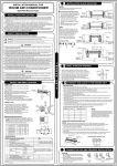
1
Series 200
Monitor
User Guide
.
.
Contents
Foreword
Statements of Compliance
Warranty
Warning
For Your Safety
Monitor Components
About Your Monitor
Assembly, Wiring and Installation
1
2
3
5
5
6
6
7
Assembly
Installing the Battery Pack
Rechargeable Batteries
Safety
Using the Battery Pack
Charging and Discharging the Batteries
Removing the Battery Pack
Installing the AC/DC Adaptor
Warm Up
Monitor and Sensor Versions
7
7
8
8
8
9
9
10
10
10
Operating Instructions
11
Turning the Monitor on and off
Sensor Head Failure
11
12
Using the Menus & Key Functions
13
Zero Calibration
Changing Unit of Measurement
Max Min Average Measurement Cycle
Alarm Mute (Perc only)
Alarm (Perc only)
Alarm Level (Perc only)
13
14
14
15
15
16
Troubleshooting
Care and Maintenance
Disposal /Recycling
Specifications – Series 200
Drawings
Sensor Head Specifications
17
18
19
19
20
21
.
.
Foreword
Statements of Compliance
Copyright Aeroqual Limited. All rights reserved. Reproduction, transfer, distribution or
storage of part or all of the contents of this document in any form without the prior
written permission of Aeroqual Limited is prohibited.
“Aeroqual” and “Aeroqual Limited – Making the Invisible Visible” are registered
trademarks of Aeroqual Limited. Other product and company names mentioned
herein may also be trademarks or trade names.
Aeroqual operates a policy of continuous development. Aeroqual reserves the right
to make changes and improvements to any of the products described in this
document without prior notice.
Under no circumstances shall Aeroqual be responsible for any loss of data or income
or any special, incidental, consequential or indirect damages howsoever caused.
The contents of this document are provided "as is". Except as required by applicable
law, no warranties of any kind, either express or implied, including, but not limited to,
the implied warranties of merchantability and fitness for a particular purpose, are
made in relation to the accuracy, reliability or contents of this document.
Aeroqual reserves the right to revise this document or withdraw it at any time without
prior notice. The availability of particular products may vary by region. Please check
with the Aeroqual dealer nearest to you.
1.
2.
3.
The Aeroqual Series 200 Monitor and Remote Adaptor Kit comply with EN
50082-1:1997
The Aeroqual Series 200 Monitor and Remote Adaptor Kit comply with EN
50081-1:1992
The Aeroqual Series 200 Monitor and Remote Adaptor Kit comply with Part
15 of the FCC Rules. Operation is subject to the following two conditions:
(1) these devices may not cause harmful interference, and (2) these
devices must accept any interference received, including interference that
may cause undesired operation.
NOTE: This equipment has been tested and found to comply with the limits
for a Class B digital device, pursuant to Part 15 of the FCC Rules. These
limits are designed to provide reasonable protection against harmful
interference in a residential installation. This equipment generates, uses
and can radiate radio frequency energy and, if not installed and used in
accordance with the instructions, may cause harmful interference to radio
communications. However, there is no guarantee that interference will not
occur in a particular installation. If this equipment does cause harmful
interference to radio or television reception, which can be determined by
turning the equipment off and on, the user is encouraged to try to correct
the interference by one or more of the following measures:
—
—
—
29.02.08
—
Reorient or relocate the receiving antenna.
Increase the separation between the equipment and receiver.
Connect the equipment into an outlet on a circuit different from
that to which the receiver is connected.
Consult the dealer or an experienced radio/TV technician for
help.
© Aeroqual Limited 2006. All rights reserved.
Aeroqual Limited
109 Valley Road, Mount Eden, Auckland 1024, New Zealand
phone
+64 9 623 3013
fax
+64 9 623 3012
web
www.aeroqual.com
. 1 .
. 2 .
Conditions
Warranty
1.
The warranty is valid only if the original receipt issued to the original purchaser by the
dealer, specifying the date of purchase, is presented with the product to be repaired or
replaced. Aeroqual reserves the right to refuse warranty service if this information has
been removed or changed after the original purchase of the product from the dealer.
2.
If Aeroqual repairs or replaces the product, the repaired or replaced product shall be
warranted for the remaining time of the original warranty period or for ninety (90) days
from the date of repair, whichever is longer. Repair or replacement may be via functionally
equivalent reconditioned units. Replaced faulty parts or components will become the
property of Aeroqual.
3.
This warranty does not cover any failure of the product due to normal wear and tear,
damage, misuse, including but not limited to use in any other than the normal and
customary manner, in accordance with Aeroqual’s user guide for use, faulty installation,
calibration and maintenance of the product, accident, modification or adjustment, events
beyond human control, improper ventilation and damage resulting from liquid or corrosion.
4.
Warranty Period
One year from the date of purchase
Six months from the date of purchase
This warranty does not cover product failures due to repairs, modifications or improper
service performed by a non-Aeroqual authorized service workshop or opening of the
product by non-Aeroqual authorized persons.
5.
Three months from the date of purchase
One year from the date of purchase
The warranty does not cover product failures which have been caused by use of nonAeroqual original accessories.
6.
This warranty becomes void if a non-Aeroqual approved AC/DC adaptor or battery is
used.
7.
Tampering with any part of the product will void the warranty.
8.
Damage to the sensors can occur through exposure to certain sensor poisons such as
silicones, tetraethyl lead, paints and adhesives. Use of Aeroqual sensors in these
environments containing these materials may (at the discretion of Aeroqual) void the
warranty on the sensor head. Exposure to gas concentrations outside of the design range
of a specific Aeroqual sensor head can adversely affect the calibration of that sensor
head and will also void this warranty as it applies to the replacement of sensor heads.
9.
Aeroqual makes no other express warranties, whether written or oral, other than
contained within this printed limited warranty. To the fullest extent allowable by law all
warranties implied by law, including without limitation the implied warranties of
merchantability and fitness for a particular purpose, are expressly excluded, and in no
event shall Aeroqual be liable for incidental or consequential damages of any nature
whatsoever, however they arise, from the purchase or use of the product, and including
but not limited to lost profits or business loss.
10.
Some countries restrict or do not allow the exclusion or limitation of incidental or
consequential damage, or limitation of the duration of implied warranties, so the preceding
limitations or exclusions may not apply to you. This warranty gives you specific legal
rights, and you may also have other rights, which may vary from country to country.
Thank you for purchasing this Aeroqual product. To get maximum use of the features
of your new product we recommend that you follow a few simple steps:
•
Read the guidelines for safe and efficient use.
•
Read all the terms and conditions of your Aeroqual Warranty.
•
Save your original receipt. You will need it for warranty repair claims.
Should your Aeroqual product need warranty service, you should return it to the
dealer from whom it was purchased or contact Aeroqual.
Our Warranty
Aeroqual warrants this product to be free from defects in material and workmanship
at the time of its original purchase by a consumer, and for a subsequent period as
stated in the following table:
Products
Series 200 monitor base
Sensor heads – all gases
Accessories
Batteries
Other Accessories
This warranty is expressly limited to the original owner who purchases the equipment
directly from Aeroqual or from an authorized Aeroqual dealer.
What we will do
If, during the warranty period, this product fails to operate under normal use and
service, due to improper materials or workmanship, Aeroqual subsidiaries, authorized
distributors or authorized service partners will, at their option, either repair or replace
the product in accordance with the terms and conditions stipulated herein.
. 3 .
. 4 .
WARNING
Monitor Components
Do not switch the monitor on before reading the User Guide.
FOR OZONE SENSOR HEADS ONLY
Do not expose the monitor to very high levels of ozone
Do not place the sensor head in an ozone stream – the monitor
is designed to measure ambient levels of ozone and uses ‘active
sampling’ to achieve this.
For Your Safety
Read these simple guidelines. Ignoring these guidelines may be hazardous.
USE SENSIBLY
Use only as per this user guide.
USE AEROQUAL APPROVED SERVICE
Only approved service personnel must work on this product.
ACCESSORIES
Use only approved accessories. Do not connect incompatible
products.
CONNECTING TO OTHER DEVICES
When connecting to any other device, read the appropriate user
guide for detailed safety instructions. Do not connect incompatible
products.
HAZARDOUS ENVIRONMENTS (Ozone Sensors Only)
Do not use the Ozone Sensors in or near volatile fuel or
chemicals.
HEALTH AND SAFETY IN THE WORKPLACE
The Aeroqual Series 200 Monitors and Sensor Heads are used to
monitor ambient gas concentrations. Aeroqual does not guarantee
user safety. In hazardous environments, an appropriate Health
and Safety plan should be in place.
.
5
.
Series 200 Monitor
The following components are supplied with the Series 200
Monitor:
Series 200 monitor base
Gas sensor head
12 VDC 800 mA AC/DC adaptor
User guide
Battery pack – 9.6 V
Please check that all these components have been supplied and
contact your dealer or Aeroqual on email at: [email protected] if
any of the components are missing.
About Your Monitor
The Aeroqual Series 200 Monitor has been specifically designed to
incorporate Aeroqual’s in-depth knowledge of accurate ambient gas
measurement. Different sensor heads are used for specific gases or
depending upon whether high or low concentrations are to be measured.
The all sensor heads are interchangeable on the same base unit.
The following information details the operation and features of the monitor:
1. The monitor is modular in design and is comprised of two main
components, a Series 200 monitor and a sensor head. This affords
the user the ability to replace faulty sensor heads without having to
replace the monitor. The monitor can be mains and/or battery powered
and either permanently mounted or used as a portable unit.
2. The sensor head is calibrated prior to delivery and does not normally
need to be re-calibrated during its life. (Specific user guides are
supplied for the special operations of particular sensor heads).
3. The Aeroqual Series 200 Monitor comes with in-built diagnostics,
which will inform the user if the sensor is not operating correctly.
4. An audible alarm is available with perchloroethylene sensors only. Both
temporary and permanent mute functions are also included with the
audible alarm.
5. Concentration unit selection. The concentration can be displayed in
either ppm or mg/m3.
6. Min / max / average measurement cycle. The monitor will display the
minimum, maximum, average and 15-minute average gas
concentrations over the measurement period.
. 6 .
Assembly, Wiring and Installation
ASSEMBLY
The following needs to be completed before the Monitor is ready for
use: • Insert the sensor head into the top of the monitor. The sensor
head is keyed to ensure the head is inserted correctly.
•
If the monitor is a mains only unit it is ready for use. If the
monitor is to be used as a portable unit with batteries then the
batteries must be installed and charged prior to use.
Installing the Battery Pack
•
Remove the battery cover from the
monitor.
•
Insert the battery power connector
into the monitor power socket in the
back of the monitor.
•
Lay the battery cable into the slot on
the back of the monitor and insert the
tail end of the battery pack into the
hinge points at the bottom of the
monitor back cover.
Rechargeable Batteries
The battery pack is used to power the monitor as a portable unit.
Please read the following information carefully before using the
battery pack to operate the Aeroqual monitor.
The Series 200 Monitor is supplied with a 9.6V (2100mA/hr Ni-MH)
battery pack.
Safety
•
•
•
•
•
•
•
Do not use the battery pack for any other purpose than
operating the Aeroqual monitor
Do not disassemble or mutilate the batteries as this may cause
burns
Do not incinerate or heat as this may cause burns, the batteries
may burst or cause the release of toxic materials
Do not short circuit as this may cause burns
Use only batteries approved by Aeroqual and recharge your
battery only with the AC/DC adaptors supplied by Aeroqual.
Never use any charger or battery that is damaged or worn out.
Batteries must be recycled or disposed of properly. They must
not be disposed of in municipal waste.
Never charge a Ni-MH in a hermitically sealed container.
•
Clip the top end of the battery pack
into the top clips, taking note to
orientate the battery pack per the
instructions on the battery pack.
•
•
Replace the battery cover on the
monitor.
The life of the battery pack will be affected by the way it is handled.
Take good care of the battery pack and follow the guidelines
suggested in the following section.
. 7 .
Using the Battery Pack
. 8 .
Charging and Discharging the Batteries
Installing the AC/DC Adaptor
•
•
•
•
•
•
•
•
•
•
•
NOTE: Battery charging occurs only when units (version 4.0
and above – as shown on the start-up screen) are switched on
or in standby mode. Older versions are not fitted with intelligent
charging and are best charged while switched off.
During charging the battery symbol on the display flashes slowly.
Battery can be charged with the sensor head installed or with the
sensor head removed from the base. (Remember to switch off the
monitor before removing the sensor head).
A intelligent Charging Circuit will stop charging the unit once
battery has been charging for 15 hours.
Unplugging the main power will reset the above charging
conditions.
New Ni-MH batteries must be fully charged prior to use. A new NiMH battery's full performance is achieved only after a number of
complete charge and discharge cycles. A fully charged battery will
run for approximately 7 hours.
(Note: Perc sensor heads require more power and will run for a
shorter time)
The battery will normally charge in approximately 10 hours in
Standby mode, in 15 hours in normal operating mode and in a
shorter period, if the battery was not fully discharged.
The batteries can be charged and discharged many times but will
eventually wear out. When the operating time is noticeably shorter
than normal, it is time to replace the batteries.
It is not necessary to fully discharge the batteries. When not using
the Series 200 Monitor as a portable unit, always plug in the mains
adaptor to recharge the batteries with the monitor switched on.
If left unused a fully charged battery will discharge itself over time.
Removing the Battery Pack
•
•
•
•
Remove the battery cover from the monitor.
Insert your thumb under the top left hand side of the battery
pack and carefully lever the battery pack out from the retaining
clips.
Unclip the connector from the monitor.
Replace the battery cover.
.9 .
•
Connect the AC/DC adaptor to the mains supply. Ensure that
the adaptor is correctly rated for the power supply.
Plug the adaptor into the monitor. The monitor can now be used
as a mains unit. If the monitor is to be used as a portable unit
the batteries will need to be charged.
Warm Up
Prior to operation the monitor must be warmed up to burn off
contaminants on the sensor. When the monitor is first switched on it
will warm up for 3 minutes. Then the reading will flash for the next 7
minutes to indicate that the sensor is still in the warm up phase. It is
recommended that the monitor is kept in Stand By mode when not
being used to keep the sensor heated and prevent the build up of
contaminants. The monitor should be run for 24 hours on mains
power prior to use if it has been switched off for more than 7 days.
Warning: Do not remove the sensor head while the
monitor is switched on. This may damage the unit. If the
sensor head is removed under these conditions, the unit will
automatically shut down.
Monitor and Sensor Versions
Turning the monitor on will display “AEROQUAL MONITOR V x.x”,
where "V x.x" represents the version of the monitor base. The
display will then show “SVXX” which indicates the software version
installed on the sensor head.
Operating Instructions
The following instructions detail the operation and set up of the
monitor.
. 10 .
Power
button
Enter
Key
conserve power between operations but keep the sensor ready to
measure the gas concentration with only a short warm up phase as
described in “Warm up” section on page 10. In this mode the display
will be as shown below:
NH3
To return the monitor to operational mode quickly press the power
button once.
TURNING THE MONITOR ON AND OFF
Operating under Battery power
To turn the monitor on, press & hold the power button until the
monitor beeps and the screen activates. The monitor will turn on
and the display will show “AEROQUAL MONITOR V x.x”,. After 5
seconds the display will change to indicate the type of sensor head.
The monitor will warm up as described in the “Warm up”
section on the previous page. Once warm up is complete the
main display will appear (for example):
A battery fuel cell will appear at the bottom of the display when the
monitor is operating under battery power only. As the battery
charge decreases, the fuel cell will indicate the battery life
remaining.
O3 LOW
0.080
ppm
O3 LOW
0.009
ppm
Note:
The number of decimal
places shown will vary
depending on the sensor
head type
To turn the monitor off, press and hold the power button for
2 seconds until the monitor beeps. The display will now be blank
and operation of the monitor will cease.
Sensor Head Failure
There are two possible Sensor failure modes, which will be
indicated by one of the following messages on the display: “Sensor Failure, Replace sensor” – The sensor head should be
replaced as this indicates that there has been a component failure or the
sensor has reached the end of its usable life.
“Sensor aging” - This indicates that the sensor has reached the end of
its usable life and the sensor head should be replaced as soon as
possible. The measurement readings can no longer be relied upon to be
within specification.
Turning Standby Mode on and off
To activate Standby Mode with the monitor on, quickly press the
power button once. This will stop operation of the monitor,
however, the sensor will be kept warm. This mode is used to
. 11 .
Using the Menus and Key Functions
To enter the setup menu press
will appear: -
. 12 .
. One of the following menus
Normal Menu
Special Perc Menu
EXIT
ZERO CAL
CONC UNIT
MIN MAX AV
Press
EXIT
ZERO CAL
CONC UNIT
MIN MAX AV
ALARM MUTE
ALARM
ALARM LEVEL
OZONE UNIT:
ppm (or)
mg/m3
Press
Press
to scroll to the desired item.
The “ZERO CAL” routine resets the zero point of the monitor.
"ZERO CAL" must be carried out under carefully controlled
conditions, as specified below:
• Minimum 24 hours warm up
• Clean air (charcoal filtered is best), no cross-sensitive gases
• Stable and low air flow around the monitor
• No vibration or movement of the monitor
• Temperature at 20°C ± 2°C (68°F ± 3.5°F)
• Relative Humidity of 50% ± 5%
to scroll down to the next menu choice.
to scroll down to the next Menu choice
The Max/Min/Average Measurement Cycle
Pressing
starts the Min Max Av routine
Press
to scroll to ‘EXIT’
to Exit out of Menu Setup.
Press
The following display will appear:VOC
O3 LOW
An incorrect "ZERO CAL" does not cause permanent damage. The
process should be repeated under the above conditions.
until the word GO appears.
Press and hold
The routine will run for about 3-10 minutes and then beep to
indicate completion. Talk to your supplier or distributor if you
have questions.
.
MIN 0.005
MAX 0.024
AV 0.015
ST 0.013
0.008
MIN
5
MAX 25
AV 15
ST
17
ppm
. 13 .
18
ppm
Repeat the above sequence to stop the Min Max Av routine.
Note:
The MIN, MAX and AVE readings are the minimum, maximum and
average readings over the period from the start of the cycle.
The ST value is the average over the last 15 minutes.
Changing Unit Of Measurement (Concentration Unit)
To enter the ‘CONC UNIT’ menu press
appear.
3’
to confirm the unit selection
Press
Zero Calibration (ZERO CAL)
Press
to scroll between ‘ppm’ or ‘mg/m
. The unit display will
. 14 .
ALARM MUTE (for PERC only)
If you select “Alarm Permanent OFF” and exit the menu, the
Note: With “Alarm Mute ON” (enabled) the alarm condition will be
muted only until the gas concentration drops below the alarm level –
remember this is a temporary mute function.
symbol
To enter the “ALARM MUTE” menu press
screen will appear: -
and the following
P will be displayed on the gas concentration screen to
indicate that the alarm has been permanently muted.
Press
to scroll down to the next menu choice.
ALARM LEVEL (for PERC only)
ALARM MUTE
OFF
Press
To enter the “ALARM LEVEL” menu press
screen will appear: -
and the following
ALARM LEVEL
50PPM
to toggle between “ALARM MUTE OFF” and
“ALARM MUTE ON”. Press
to confirm your choice and you
will return to the main menu. If you select “Alarm Mute On” and exit
Press
35PPM.
the menu, the symbol
screen.
to confirm your choice and you will return to the main
Press
menu.
Whatever alarm level you have chosen will be displayed on the
bottom left of the main display screen.
Press
will be displayed on the gas concentration
to scroll down to the next menu choice.
NOTE: The altered alarm level will remain active until the Monitor is
switched off after which it will revert to the 50PPM default level.
ALARM (for PERC only)
To enter the “ALARM” menu press
appear: -
and the following screen will
Press
to scroll up to the “EXIT” menu choice and press
exit to the main screen.
ALARM
PERMANENT
ON
Press
to toggle between 50PPM, 100PPM, 150PPM and
to toggle between “ALARM PERMANENT ON” and
“ALARM PERMANENT OFF”. Press
and you will return to the main menu.
. 15 .
to confirm your choice
. 16 .
to
Troubleshooting
Series 200
Fault Description
Possible cause
Remedy
Reading higher than
expected in the presence
of sensor gas
Sensor correct
Check calibration of gas
generator.
Interferent gas
present
Move sensor to clean air
and check reading upon
exposure to known gas
concentration
Sensor calibration lost
Power supply
unstable
Replace /refurbish sensor
Install stable power supply
Fault
Description
Possible cause
No power
Lead connection broken
Reconnect power lead
Power supply failure
Replace 12V DC power supply
Battery flat
Recharge battery
S200 damaged
Replace unit
Sensor head damaged
Insufficient warm up
Replace sensor head
Run the sensor on full power for
24-48 hours.
Local air flow too high
Air contaminated
Move the sensor to cleaner
environment and check reading
Environmental
conditions fluctuating
Sensor damaged
Background gas level
higher than normal
Replace sensor
Move sensor to clean air and
recheck baseline
Interferent gas present
Move sensor to clean air and
recheck baseline
Sensor damaged
Sensor correct
Replace sensor
Check calibration of gas
generator.
Sensor inlet contaminated
Clean sensor inlet filter and mesh
Sensor fan failed
Replace sensor
Interferent gas present
Move sensor to clean air and
check reading upon exposure to
known gas concentration
Sensor failure
when the sensor is
new
Reading high
under zero gas
conditions
Reading lower than
expected reading
in the presence of
sensor gas
Remedy
Reading unstable
Power supply current
rating incorrect
Install power supply with
correct rating
Reduce air flow
Reduce fluctuations
Care and Maintenance
Your Aeroqual Monitor is a product of superior design and quality and
should be treated with care. When using your Aeroqual Monitor:
Keep it and all its parts and accessories out of the reach of small
children.
Keep it dry. Avoid water and/or condensation as humidity and liquids
containing minerals may corrode electronic circuits.
Do not use or store in dusty, dirty areas.
Do not store or turn off the monitor in temperatures below 10°C.
Gas reactive and
decomposing before
detection
Move the monitor closer to the
source of the gas
This unit is designed for use at temperatures between -5°C and +50°C
(23°F and 120°F). Sudden changes in temperature will cause
condensation that may damage the electronic componentry.
Local air flow too high
(ozone sensors) or
too low (VOC and
ammonia sensors)
Modify the airflow into and
around sensor head.
Do not attempt to open. Non-expert handling of the device may cause
damage.
Sensor calibration lost
Replace /refurbish sensor
. 17 .
Do not drop, knock or shake as this could lead to internal damage.
Do not use harsh chemicals, cleaning solvents or strong detergents for
cleaning. Wipe with a soft cloth slightly dampened with a mild soapand-water solution.
. 18 .
Disposal / Recycling
Please note that this is an
electronic product and disposal should be in line with your local or country
legislation. The plastic casing of the product is made from a Polycarbonate /
ABS blended material (PC + ABS) and is marked accordingly.
Drawings
Specification for Series 200
Series 200 Monitor Base
PPM or mg/m3
Yes
Yes
Yes
Yes
Yes
Yes
Yes
None
None
None
12 VDC, 800 mA
9.6V (2100mA/hr Ni-MH )
Yes
Screw fix
Yes
IP20 & NEMA 1 equivalent
195 x 122 x 54 (mm);
7V x 4¾ x 2X (in)
< 460 g; < 16 oz
Part 15 of FCC Rules
EN 50082-1: 1997
EN50081-1: 1992
Measurement units
Removable / replaceable sensor head
On-board alarm*
Alarm status displayed *
Low battery indication
Alarm mute function*
Sensor condition status
Stand-by mode
External signal for alarms & control
External signal functions
Analogue output
Power supply
Rechargeable battery pack
Portable
Permanently fixable
Remote Sensor Capability
Enclosure rating
Size (with sensor head)
Weight (with sensor head and battery)
Approvals
Depressions in
the battery cover
demarcating the
screw-hole
positions for
fixing the unit to
the wall.
* Perc sensor only
. 19 .
.
20
.
SENSOR HEAD SPECIFICATIONS (cont’d)
SENSOR HEAD SPECIFICATIONS
Sensor
Maxi
Calibr
mum
ated
Expos
Range
ure
LDL
Relativ
e
Respo Sampli Operat
ing
ng
Resolu nse
Humidi
Temp.
tion
ty
Time Metho (environme
(non(T90)
d5
ntal)
condensin
Accuracy
Maxi
mum
Expo
sure
LDL
Ozone
0.5 - 20
ppm 2
0.5 20
25
10
ppb
<± 10% 0.5 2 ppm
<± 15% 2 20 ppm
0.01 ppm
< 35 s
F
Ozone
(leak)
For ozone leak detection at IDLH (Immediate
Dangerous to Life & Health – 5ppm)
0.01 ppm
< 10 s
F
Sensor
g)
Ammonia
0 - 100 ppm
0 - 100
200
0.5
ppm
<± 5ppm 0 100 ppm
0.1 ppm
< 60 s
F
-20°C to
40°C
5 to
95%
Ammonia
(leak)
0 - 1000 ppm
01000
2000
2 ppm
<± 15%
1 ppm
< 60 s
F
-20°C to
40°C
5 to
95%
Carbon
monoxide
0 - 100 ppm
0 - 100
200
0.5
ppm
<± 5 ppm
0.1 ppm
< 150 s
F
0°C to
40°C
5 to
95%
Carbon
monoxide
0 - 1000 ppm
01000
2000
1 ppm
<± 10%
1 ppm
< 150 s
F
0°C to
40°C
5 to
95%
Carbon
dioxide
0 - 2000 ppm
02000
NA
-
<± (40 ppm +
3%)
10 ppm
< 60 s
F
0 to
40°C
5 to
95%
Carbon
dioxide
0 - 5000 ppm
05000
NA
<± (150 ppm +
5%)
10 ppm
0 to
40°C
5 to
95%
Carbon
dioxide
0 - 5.00%
05.00%
NA
<± 5%
0.01%
0 to
40°C
5 to
95%
05000
20000
5 ppm
<± 10 %
1 ppm
< 90 s
F
-20°C to
40°C
5 to
95%
Hydrogen
sulphide
0 - 10 ppm 1
0 - 10
25
10 ppb
<± 0.5 ppm
0.01
ppm
< 60 s
D
-20°C to
40°C
5 to
95%
Hydrogen
sulphide
0 - 50 ppm
0 - 50
100
0.05
ppm
<± 1 ppm 0 10 ppm
<± 2 ppm 10 50 ppm
0.1 ppm
< 60 s
D
-20°C to
40°C
5 to
95%
Methane
0 - 10000
ppm
09999
10000
-
<± 15%
1 ppm
< 60 s
F
0°C to
40°C
30 to
80%
Ozone
0 - 0.150 ppm
00.150
0.250
1 ppb
<± 0.005 ppm
0.001
ppm
< 70 s
F
-5°C to
40°C
5 to
95%
Ozone
0 - 0.5 ppm
00.500
1
1 ppb
<±0.008ppm 0
- 0.1ppm
<± 10% 0.1 0.5ppm
0.001
ppm
< 60 s
F
-5°C to
40°C
5 to
95%
Hydrogen
0 - 5000 ppm
1
-
-
.
21
.
< 60 s
< 60 s
F
F
Sam
pling
Meth
od5
Calib
rated
Ran
ge
NMHC 3,4
0 - 25 ppm
Accuracy
Resolut
ion
Respon
se Time
(T90)
0 - 25
50
0.1
ppm
<± 10% 0.1 25 ppm
0.1 ppm
< 60 s
F
Oper
ating
Tem
p.
Relat
ive
Hum
idity
(environ
mental)
(nonconden
sing)
-5°C
to
40°C
5 to
95%
-5°C
to
40°C
-20°C
to
40°C
5 to
95%
5 to
95%
Perchloroe
thylene
0 - 200
ppm
Sulphur
dioxide
0 - 10 ppm
Sulphur
dioxide
0 - 100
ppm
0200
250
1 ppm
<± 5 ppm 0 50 ppm
<± 10% 50 200 ppm
1 ppm
<5s
(T50)
F
0°C
to
40°C
30 to
80%
0 - 10
20
0.2
ppm
<± 0.5 ppm
0.01 ppm
< 60 s
F
-20°C
to
40°C
5 to
95%
0100
200
0.5
ppm
<± 10%
0.1 ppm
< 60 s
D
-20°C
to
40°C
5 to
95%
VOC 025ppm4
0 - 25
50
0.1
ppm
<± 10% 0.1 25 ppm
0.1 ppm
< 60 s
F
VOC 0-500
ppm4
0500
1000
1 ppm
<± 10%
1 ppm
< 60 s
F
Other
Gases
-20°C
to
40°C
-20°C
to
40°C
5 to
95%
5 to
95%
Contact Aeroqual with specific requirements for gas and concentration
Temperatu
re
-20 to
100°
C
-40 to
120°
C
0.01°
C
<± 0.3°C
0.01°C
<1s
-
Humidity
0 to
100%
100%
1%
RH
2% RH
1% RH
<1s
-
-40 to
120°
C
-40 to
120°
C
1
Other specific concentrations available on request
2
Accuracy < 0.5 ppm is unspecified (for applications that require accurate measurement < 0.5 ppm use
low or ultra-low sensor heads)
3
Non Methane Hydrocarbon sensor (low sensitivity to alcohols & esters)
4
Calibrated against isobutylene. Other specific VOC calibrations are available on request
5
D= diffusion, F=fan
.
22
.
0 to
100%
0 to
100%