1
INSTRUCTION MANUAL
CS225
Temperature String
October
Copyright © 2013
Campbell Scientific (Canada)Corp.
Table of Contents
1. Introduction ................................................................. 2
2. Cautionary Statements ............................................... 2
3. Initial Inspection.......................................................... 3
4. Overview ...................................................................... 3
5. Specifications.............................................................. 3
5.1 SGB3 3-Line Surge Protector ................................................................... 4
5.2 CS225 Temperature String ....................................................................... 5
6. Installation ................................................................... 6
6.1 Siting ......................................................................................................... 6
6.2 Mounting................................................................................................... 6
7. Operation ..................................................................... 6
7.1. Wiring ...................................................................................................... 7
7.1.1 Long Cables .................................................................................... 8
7.1.2 Power Conservation ........................................................................ 8
7.2 Reading the CS225 ................................................................................. 10
7.2.1 SDI-12 Addressing ........................................................................ 11
7.2.2 Slow Sequence Program Instructions ............................................ 12
7.2.3 CS225 Metadata ............................................................................ 14
7.2.4 Example Programs ........................................................................ 16
7.5 Changing the SDI-12 Address Using LoggerNet and a Datalogger........ 19
7.5.1 CR1000 & CR800 series Dataloggers ........................................... 19
8. Maintenance and Calibration ................................... 21
9. Troubleshooting........................................................ 21
Figures
Figure 7—1 SGB3 3-Line Surge Protector .......................................................................................................... 7
Figure 7—2 Screen capture of SDI-12 Transparent Mode on CRBasic CR800 Datalogger using control
port 1 and prompting for SDI-12 addresses ...................................................................................................... 20
1
CS225 Temperature String
CS225 Temperature String
1. Introduction
The CS225 temperature string uses SDI-12 digital technology for simple
integration and reliability. The CS225 consists of an arrangement of
temperature sensors mounted in rugged steel reinforced cable. Temperature
points are overmolded to provide long-term protection in all mediums. Each
CS225 is manufactured to the client’s specific requirements and includes the
SGB3 to provide electrical surge protection.
Before using the CS225 please study:
x
x
Section 2, Cautionary Statements
Section 7.1, Wiring
More details are available in the remaining sections.
2. Cautionary Statements
NOTE
x
Although the CS225 is designed to be a rugged and reliable device for
field use, care should be taken when handling or moving it to avoid
damage.
x
There are no user-serviceable parts and any attempt to disassemble the
device will void the warranty.
x
The CS225 must be used in conjunction with the SGB3 in order to protect
against electrical surges.
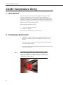
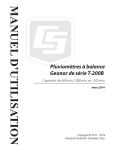
Do not make tight bends near the temperature sensor(s). Doing
so has the potential to damage the sensor assembly. The
minimum bend radius at any sensor location is 6”/15 cm (12”/30
cm diameter). See image below.
X
2
CS225 Temperature String
3. Initial Inspection
x
Upon receipt of the CS225, inspect the packaging and contents for
damage. File any damage claims with the shipping company. Immediately
check package contents against the shipping documentation. Contact
Campbell Scientific about any discrepancies.
x
The model number and cable length are printed on a label at the
connection end of the cable. Check this information against the shipping
documents to ensure the expected product and cable length are received.
x
The CS225 is shipped with a SGB3, FIN4COND cable, and a
ResourceDVD.
x
4. Overview
The CS225 temperature string makes use of digital sensor technology allowing
for a simple 3-wire integration. The CS225 consists of an arrangement of
overmolded temperature points mounted in a rugged steel reinforced cable.
Each CS225 is manufactured to the client’s specific requirements.
The CS225 is suited for a wide variety of applications and environments that
require temperature profiling. The completely sealed cable assembly permits
the CS225 to be buried, submerged or integrated directly into structures.
Examples of some applications include temperature profiling in boreholes,
soils, water, and frost & permafrost monitoring.
The purpose of the SGB3 is to provide adequate surge protection for the CS225
Temperature String. The case of the SGB3 is suited for mounting to a back
plate with 1 inch on centre spacing.
5. Specifications
Features:
x Accurate and stable measurements
x Each sensor is individually addressed and referenced to its depth
x Low power consumption
x Digital SDI-12 output
Compatibility
Dataloggers:
CR200(X) series
CR800 series
CR1000
CR3000
CR5000
CR510
CR10(X)
CR23X
3
CS225 Temperature String
5.1 SGB3 3-Line Surge Protector
4
Operating Range:
-55q to +85qC
Maximum Voltage:
±28 Vdc / 20Vac
(L1, L2, L3 with respect to G terminals)
Maximum Current:
2 A per terminal, 4 A total
(requires both ground terminals for return current)
Maximum rated surge:
1200 Amps (8/20 us)
CS225 Temperature String
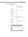
5.2 CS225 Temperature String
Operating Range:
-55q to +85qC
Accuracy:
Typical - r2qC over -40q to +85qC,
Worst-case - rqC over -40q to +85qC;
±0.5qC over -55qWRqC
(includes lifetime drift of sensor)
Resolution:
0.0078qC
Measurement Update
Interval:
1 second (automatic), occurs in quiescent mode
Warm-up Time:
10 seconds
Maximum Sensors
per String:
36 sensors
Maximum Pressure:
50 PSI
Supply Voltage:
9 to 28 Vdc
Current Consumption:
Quiescent: # sensors * 1.0 mA (max)
Active (during SDI-12 communications): 20 mA +
(# sensors * 1.0 mA)
Temperature Point
Diameter:
Maximum Cable
Length:
Minimum Sensor
Spacing:
NOTE
2.22 cm (0.875 in)
152 m (500 ft), individual CS225 and datalogger
SDI-12 terminal maximum
15cm (5.9 in)
The furthest temperature point from the datalogger (or the
temperature point at the end of the string) is addressed starting at
‘1’. Each temperature point going up the string towards the
datalogger changes by one address number/letter.
5
CS225 Temperature String
6. Installation
6.1 Siting
The CS225 is meant to be installed in the required orientation within the
medium that is to be monitored. In order to make the most representative
measurement it is important that consistent contact be made between the
Temperature String and the medium. The location of the Temperature String
should be representative of the intended application.
The CS225 consists of two distinct segments, the lead and the sensor array.
The lead length accounts for the length of cable required to reach between the
datalogger and the sensor array. The sensor array length accounts for the
length of cable required to incorporate all temperature sensors in their
necessary configuration.
The installation position of the string and its measurement points are
referenced from the first sensor position at the end of the sensor array. This
information needs be addressed as part of the sensor configuration process.
Please contact one of our Measurement Consultants for more details.
6.2 Mounting
The CS225 will need to be orientated and secured in the measurement medium.
Any materials removed in order to install the CS225 should be retained for use
as backfill.
If a burial depth is required for each temperature sensor you will need to know
the length of the sensor array, the “measurement from end” metadata of each
sensor in the array, and any offset used during installation of the string. With
this information you will be able to calculate the depth of each temperature
sensor.
Care should be taken to orientate the lead cable of the CS225 towards the
datalogger to avoid loops or strain on the cable. A suitable trench or conduit
will also need to be considered in order to protect the lead cable from damage.
The SGB3 is to be mounted inside the datalogger enclosure, and can be secured
to the enclosure backplate with the supplied hardware.
7. Operation
When power is supplied to the CS225, the internal electronics will
continuously measure the temperature approximately once per second. Every
output obtained from the sensor is a running average of 10 consecutive, 1
second readings. The accuracy specification is based on an average of 10
consecutive readings. For this purpose after initial power up, a delay of 10
seconds is recommended to obtain the best accuracy.
Outputs of both lifetime and user resettable minimum and maximum
temperatures are also available during powered operation from each
temperature point in the CS225. The user resettable minimum and maximum
temperatures can be used to monitor specific seasons or periods of measure,
6
CS225 Temperature String
without having to review the entire data set. The lifetime minimum and
maximum temperatures are used for maintenance and warranty records.
7.1. Wiring
Connections for the SGB3 and CS225 to Campbell Scientific dataloggers are
given in Table 7-1 and 7-2. When Short Cut for Windows software is used to
create the datalogger program, the sensor should be wired to the channels
shown on the wiring diagram created by Short Cut.
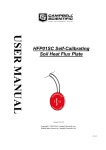
The SGB3 is required in order to protect against electrical surges. The SGB3
makes use of the included FIN4COND cable to make final connections to the
datalogger.
Figure 7—1 SGB3 3-Line Surge Protector
TABLE 7-1. CS225 Connection to
SGB3
Colour
Description
CS225
Red
Power
L1
Green
SDI-12 Signal
L2
Not Used
L3
Black
Power Ground
G
Clear
Shield
G
7
CS225 Temperature String
TABLE 7-2. SGB3 Connection to Campbell Scientific Dataloggers
CR200(X)
CR800
CR1000
CR3000
CR5000
CR510
CR500
CR10(X)
CR23X
Colour
SGB3
Description
Red
L1
12V
12V
12V
Green
L2
* Control Port
Control Port
Control Port
L3
Not Used
Not Used
Not Used
Black
G
G
G
Clear
G
G
* dedicated SDI-12 port on CR5000
To use more than one string per datalogger, you can either connect the different
strings to different SDI-12 compatible ports on the datalogger or change the
SDI-12 addresses of the strings and let them share the same connection. Using
the SDI-12 addressing method minimizes the use of ports on the datalogger
(see below for limits on the total cable length).
There are two ways to set the SDI-12 address of the CS225:
x
By sending the required commands to the sensors via an SDI-12
recorder/datalogger that allows talk through to the sensor.
x
By loading a program into the datalogger that sends the required
commands (see Section 7.5, Changing the SDI-12 Address Using
LoggerNet, and a Datalogger).
7.1.1 Long Cables
As the measurement data is transferred between the Temperature String and
datalogger digitally, there are no offset errors incurred with increasing cable
length as seen with analog sensors. However, with increasing cable length
there is still a point when the digital communications will break down,
resulting in either no response from the sensor or corrupted readings. The
original SDI-12 standard specifies the maximum total cable length for the cable
as being 61 meters (200 ft), but we are able to exceed this limit by:
x
Using low capacitance, low resistance, screened cable.
x
Ensuring that the power ground cable has low resistance and is connected
to the same ground reference as the datalogger control ports.
7.1.2 Power Conservation
The CS225 draws less than 1 mA of current per sensor between polling
sessions from its 12 V supply. In many applications this is minimal compared
to overall system power use, so the sensor can be permanently powered to
avoid the warm up period.
In very low power applications battery power can be conserved by turning the
12 V supply to the CS225 on a minimum of 10 seconds before the CS225 is
8
CS225 Temperature String
polled for a measurement (allowing for the warm-up period) and then turning it
off afterwards.
This switching can be achieved in different ways depending on the type and
model of your datalogger. If available, the switched 12 V output of the
datalogger can be used.
9
CS225 Temperature String
7.2 Reading the CS225
When power is supplied to the CS225 the internal electronics will continuously
measure temperature at a rate of approximately once per second. Every output
measurement (“aR0!” or “aM0!”) obtained from the sensor is a running
average of 10 consecutive readings. For this purpose after initial power up, a
delay of 10 seconds is recommended to obtain the best accuracy.
As the sensor is obtaining a measurement every second, it is recommended to
use the Continuous measurement command (aR0!) to obtain the temperature
readings. Using the “aR0!” commands will reduce the time taken in
comparison to the “aM0!” to obtain a reading via the SDI-12 protocol. The
lifetime and user resettable minimum and maximum temperature values are
single 1 second readings. For more details see Table 7-3.
The CS225 complies with a subset of the SDI-12 1.3 instruction set.
Specifically, it supports these SDI-12 commands:
x
a! acknowledge active of individual sensor
x
aI!, send identification
x
aR! (aR0! To aR7!), continuous measurements of the sensor. The R
command provides a faster means of obtaining the readings for sensors
that can provide continuous measurements. This instruction usually takes
less than 300 milliseconds to execute.
x
aM!, initiate measurement (and the subsequent aD0! “get data” command
which is automatically sent by a Campbell Scientific datalogger). This
instruction usually takes about 700 milliseconds to execute.
x
aAb!, change address a to b
Where in all cases “a” is the address of the sensor and “!” is the command
terminator. These two characters are normally sent implicitly by Campbell
Scientific dataloggers.
The CS225 output is measured using a standard SDI-12 instruction to read the
data from an SDI-12 sensor. For CRBasic dataloggers, the SDI12Recorder()
instruction is used. For Campbell Scientific Edlog dataloggers, Instruction 105
is used. If using the sensor with other SDI-12 recorders, please refer to your
system’s documentation.
NOTE
10
In any configuration of CS225 that includes more than one
sensor, the CS225 will not respond to the “?!” SDI-12 command
as each individual sensor will respond at the same time thus
disrupting all outputs. Use the “aI!” command in a trial & error
fashion if you need to determine the individual addresses of
temperature sensors.
CS225 Temperature String
TABLE 7-3 SDI-12 Commands for the CS225
SDI-12
Command
Variable Name
Description
aR0!
Temperature value
Temperature - floating point (°C)
aR1!
Serial number, location number,
depth value (in cm)
Serial number, location number, depth
value (in cm)
aR2!
Read user resettable min temperature
Min. temperature - floating point (°C)
aR3!
Read user resettable max temperature
Max. temperature - floating point (°C)
aR4!
aR5!
Read lifetime min temperature
Read lifetime max temperature
aR6!
Read & reset user resettable min
temperature
aR7!
Read & reset user resettable max
temperature
aV!
Verification command
Min. temperature - floating point (°C)
Max. temperature - floating point (°C)
Min. temperature - floating point (°C).
This value constitutes the minimum of all
1 second measurements taken since the
previous aR6! Command.
Max. temperature - floating point (°C).
This value constitutes the maximum of all
1 second measurements taken since the
previous aR6! Command.
S1 = BootRom Signature
S2 = Firmware Signature
aAb!
Change Address command
aI!
SDI-12 Identification command
Valid addresses in sequence are:
1-9 / A-Z / a-z (no Address 0)
Sending a broadcast message with the
address change “{“ can correct units that
have conflicting addresses.
X13CAMPBELLCS225 1.0 SN:XXXXX
7.2.1 SDI-12 Addressing
The CS225 comes pre-programmed with addresses from the factory. However,
if ever needed the address of temperature sensors can be changed. This may be
necessary if two CS225 strings need to be placed in the same SDI-12 channel
in order to avoid duplicate addresses on the same SDI-12 channel.
The starting address will be 1 and this will coincide with the first temperature
sensor, which is located at the end of the sensor array. It is recommended to
start the readdressing process with the largest temperature sensor address to
avoid duplicate addresses.
NOTE
When readdressing temperature sensors you must avoid giving
multiple sensors the same address. If this does occur you will no
longer be able to communicate with these sensors. Use the
“aA{!” Command, where “a” is the affected address. This will
reset the affected sensors to their factory configured address
value.
11
CS225 Temperature String
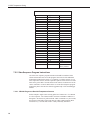
Table 7-4 SDI-12 Addresses & Positions
Numeric Set
1/1
2/2
3/3
4/4
5/5
6/6
7/7
8/8
9/9
Uppercase Set
A / 10
B / 11
C / 12
D / 13
E / 14
F / 15
G / 16
H / 17
I / 18
J / 19
K / 20
L / 21
M / 22
N / 23
O / 24
P / 25
Q / 26
R / 27
S / 28
T / 29
U / 30
V / 31
W / 32
X / 33
Y / 34
Z / 35
Lowercase Set
a / 36
b / 37
c / 38
d / 39
e / 40
f / 41
g / 42
h / 43
i / 44
j / 45
k / 46
l / 47
m / 48
n / 49
o / 50
p / 51
q / 52
r / 53
s / 54
t / 55
u / 56
v / 57
w / 58
x / 59
y / 60
a / 61
{ - reset to
factory address
7.2.2 Slow Sequence Program Instructions
Use of the slow sequence program instructions should be considered if the
CS225 measurement will exceed the program scan interval of the additional
instruments included in the station. For example, if a CS225 consists of 17 or
more temperature sensors, the time required to poll all sensors and receive data
back can be greater than 5 seconds based on the 300 ms execution time for the
“aR0!” command. For more details on the use of the Slow Sequence program
instructions please reference the related LoggerNet help or relevant datalogger
manual.
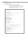
7.2.2.1 CR1000 Program to Read 20 Temperature Sensors
In this example a single CS225 is being polled on Control Port 1 of a CR1000
in a slow sequence. The CS225 includes 20 sensors with SDI-12 addresses 1
through 20. Each sensor is polled with the “aR0!” command every 60 seconds,
and stored to a data table on the same interval. Other common station data is
measured every 5 seconds and stored to a daily and hourly data tables.
12
CS225 Temperature String
'CR1000 Series Datalogger
'The following Sample program reads a CS225 string that has 20 temperature Sensors
'Declare Public Variables
Public PTemp, batt_volt
'Enter the number of temperature sensors that are in the string (will need to be adjusted
to fit specific applications)
Const NumTempSensors=20
'Uses the control port C1 on the CR1000 (valid port options are 1,3,5,7)
Const CS225_SDI12_Port=1
Public CS225Temp(NumTempSensors) As Float
Dim i As Long
'Define Data Tables
DataTable (Daily,1,-1)
DataInterval (0,1440,Min,10)
Minimum (1,batt_volt,FP2,0,False)
Maximum (1,batt_volt,FP2,0,False)
Average (1,batt_volt,FP2,0)
EndTable
DataTable (Hourly,1,-1)
DataInterval (0,60,Min,10)
Minimum (1,PTemp,FP2,0,False)
Maximum (1,PTemp,FP2,0,False)
Average (1,PTemp,FP2,0)
EndTable
DataTable (One_Minute,1,-1)
DataInterval (0,60,Sec,10)
Sample (NumTempSensors,CS225Temp(),IEEE4)
EndTable
'Define Subroutines
'*****************************************************************************
'* --------------------- ConvertNumToSDI12address() ---------------------- *
'* Convert SDI-12 character address (0->9, A->Z, & a->z) to number value
*
'* (0->61).
*
'*****************************************************************************
Function ConvertNumToSDI12address(address As Long) As String * 1
Select Case address
Case 0 To 9 'ASCII Code 48->57 = 0->9
Return(CHR(address + 48))
Case 10 To 35'ASCII Code 65->90 = A->Z = 10->35
Return(CHR(address + 55))
Case 36 To 61'ASCII Code 97->122 = a->z = 36->61
Return(CHR(address + 61))
EndSelect
Return("")
EndFunction 'ConvertNumToSDI12address()
'EndSub
'Main Program
BeginProg
Scan (5,Sec,0,0)
PanelTemp (PTemp,250)
Battery (batt_volt)
CallTable Daily
CallTable Hourly
13
CS225 Temperature String
NextScan
'Poll CS225 in Slow Sequence every minute
SlowSequence
Scan (60,Sec,3,0)
'Read the current Temperature Value
For i=1 To NumTempSensors
SDI12Recorder (CS225Temp(i),CS225_SDI12_Port,ConvertNumToSDI12address(i),"R0!",1.0,0)
Next
CallTable One_Minute
NextScan
EndProg
7.2.3 CS225 Metadata
Every temperature point in a string includes the following Meta Data, which
can be retrieved using the aR1! SDI-12 command. This information can be
used to identify details of the temperature string and its individual temperature
points.
Table 7-5 Meta Data Details
Name
14
Value Range
Description
Serial
Number
0 to 65534
The serial number that is unique to each sensor unit.
Location
Number
1 to 255
Each temperature sensor within a string is assigned its
own unique location number, which by default is in
relation with the SDI-12 address (See Table 7-4).
Measurement
from End
Value
0 to 65535 cm
This value is in centimetres (cm). These are intended
to reflect the distances of a sensor from the end of the
sensor array. The bottom most temperature point
would be designated as 0 cm. If the next temperature
point below were 20 cm away, then its Measurement
from End value would be 20 cm. Users may designate
other starting values. These can be configured at the
time of ordering.
CS225 Temperature String
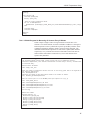
7.2.3.1 CR1000 Program to Read the Meta Data of 15 Sensors Daily
'CR1000 Series Datalogger
'The following Sample program reads a CS225 string that has 15 temperature Sensors
'Declare Public Variables
Public PTemp, batt_volt
'Enter the number of temperature sensors that are in the string (will need to be adjusted
to fit specific applications)
Const NumTempSensors=15
'Calculate the number of Meta Data points based on the number of sensors
Const MetaData_pts=NumTempSensors*3
'Uses the control port C1 on the CR1000 (valid port options are 1,3,5,7)
Const CS225_SDI12_Port=1
Public CS225Meta(NumTempSensors,3) As Float
Dim i As Long
'Define Data Tables
DataTable (MetaData,1,-1)
DataInterval (0,1,Day,10)
Sample (MetaData_pts,CS225Meta(),FP2)
EndTable
'Define Subroutines
'*****************************************************************************
'* --------------------- ConvertNumToSDI12address() ---------------------- *
'* Convert SDI-12 character address (0->9, A->Z, & a->z) to number value
*
'* (0->61).
*
'*****************************************************************************
Function ConvertNumToSDI12address(address As Long) As String * 1
Select Case address
Case 0 To 9 'ASCII Code 48->57 = 0->9
Return(CHR(address + 48))
Case 10 To 35'ASCII Code 65->90 = A->Z = 10->35
Return(CHR(address + 55))
Case 36 To 61'ASCII Code 97->122 = a->z = 36->61
Return(CHR(address + 61))
EndSelect
Return("")
EndFunction 'ConvertNumToSDI12address()
'EndSub
'Main Program
BeginProg
Scan (60,Sec,0,0)
PanelTemp (PTemp,250)
Battery (batt_volt)
'Read the Meta Data from the sensor daily
'Also read if a non-valid serial number is present (Startup values should be zero).
'A valid serial number will be greater than 1
If (CS225Meta(1,1) < 1) OR (IfTime (0,1440,Min)) Then
For i=1 To NumTempSensors
SDI12Recorder(CS225Meta(i,1),CS225_SDI12_Port,ConvertNumToSDI12address(i),"R1!",1.0,0)
Next
EndIf
CallTable MetaData
NextScan
EndProg
15
CS225 Temperature String
7.2.4 Example Programs
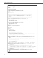
7.2.4.1 CR1000 Program for Measuring 15 Sensors Every 60 Seconds
In this example a single CS225 is being measured on Control Port 1 of a
CR1000. The CS225 includes 15 sensors with SDI-12 addresses 1 through 15.
Each sensor is polled with the “aR0!” command every 60 seconds, and stored
to a data table on the same interval. Other common station data is measured
every 60 seconds and stored to a daily data table.
'CR1000 Series Datalogger
'The following Sample program reads a CS225 string that has 15 temperature Sensors
'Declare Public Variables
Public PTemp, batt_volt
'Enter the number of temperature sensors that are in the string (will need to be adjusted
to 'fit specific applications)
Const NumTempSensors=15
'Uses the control port C1 on the CR1000 (valid port options are 1,3,5,7)
Const CS225_SDI12_Port=1
Public CS225Temp(NumTempSensors) As Float
Dim i As Long
'Define Data Tables
DataTable (Daily,1,-1)
DataInterval (0,1440,Min,10)
Minimum (1,batt_volt,FP2,0,False)
Maximum (1,batt_volt,FP2,0,False)
Average (1,batt_volt,FP2,0)
Minimum (1,PTemp,FP2,0,False)
Maximum (1,PTemp,FP2,0,False)
Average (1,PTemp,FP2,0)
EndTable
DataTable (TempSample,1,-1)
DataInterval (0,60,Sec,10)
Sample (NumTempSensors,CS225Temp(),IEEE4)
EndTable
'Define Subroutines
'*****************************************************************************
'* --------------------- ConvertNumToSDI12address() ---------------------- *
'* Convert SDI-12 character address (0->9, A->Z, & a->z) to number value
*
'* (0->61).
*
'*****************************************************************************
Function ConvertNumToSDI12address(address As Long) As String * 1
Select Case address
Case 0 To 9 'ASCII Code 48->57 = 0->9
Return(CHR(address + 48))
Case 10 To 35'ASCII Code 65->90 = A->Z = 10->35
Return(CHR(address + 55))
Case 36 To 61'ASCII Code 97->122 = a->z = 36->61
Return(CHR(address + 61))
EndSelect
Return("")
EndFunction 'ConvertNumToSDI12address()
'EndSub
16
CS225 Temperature String
'Main Program
BeginProg
Scan (60,Sec,0,0)
PanelTemp (PTemp,250)
Battery (batt_volt)
'Read the current Temperature Value
For i=1 To NumTempSensors
SDI12Recorder (CS225Temp(i),CS225_SDI12_Port,ConvertNumToSDI12address(i),"R0!",1.0,0)
Next
CallTable Daily
CallTable TempSample
NextScan
EndProg
7.2.4.2 CR1000 Program for Measuring 15 Sensors Every 5 Minutes
In this example a single CS225 is being measured on Control Port 1 of a
CR1000. The CS225 includes 15 sensors with SDI-12 addresses 1 through 15.
Each temperature sensor is polled both on power up and daily with the “aR1!”
command to determine metadata, which is stored in a daily data table. The
minimum and maximum temperature of each sensor is polled (aR6! and aR7!
respectively) every 5 minutes and stored to a data table on the same interval.
Other common station data is measured every 60 seconds and stored to a
separate daily data table.
'CR1000 Series Datalogger
'The following Sample program reads a CS225 string that has 15 temperature Sensors.
'Individual temperatures, user minimum & maximum are recorded every 5 minutes, and Meta Data
'is collected daily.
'Declare Public Variables
Public PTemp, batt_volt
'Enter the number of temperature sensors that are in the string (will need to be adjusted to
'fit specific application)
Const NumTempSensors=15
'Calculate the number of Meta Data points based on the number of sensors
Const MetaData_pts=NumTempSensors*3
'Uses the control port C1 on the CR1000 (valid port options are 1,3,5,7)
Const CS225_SDI12_Port=1
Public
Public
Public
Public
CS225Temp(NumTempSensors) As Float
CS225TempUserMax(NumTempSensors) As Float
CS225TempUserMin(NumTempSensors) As Float
CS225Meta(NumTempSensors,3) As Float
Dim i As Long
'Define Data Tables
DataTable (Daily,1,-1)
DataInterval (0,1,Day,10)
Minimum (1,batt_volt,FP2,0,False)
Maximum (1,batt_volt,FP2,0,False)
Average (1,batt_volt,FP2,0)
Minimum (1,PTemp,FP2,0,False)
Maximum (1,PTemp,FP2,0,False)
Average (1,PTemp,FP2,0)
EndTable
17
CS225 Temperature String
DataTable (MetaData,1,-1)
DataInterval (0,1,Day,10)
Sample (MetaData_pts,CS225Meta(),FP2)
EndTable
DataTable (TempSample,1,-1)
DataInterval (0,5,Min,10)
Sample (NumTempSensors,CS225TempUserMin(),IEEE4)
Sample (NumTempSensors,CS225TempUserMax(),IEEE4)
EndTable
'Define Subroutines
'*****************************************************************************
'* --------------------- ConvertNumToSDI12address() ---------------------- *
'* Convert SDI-12 character address (0->9, A->Z, & a->z) to number value
*
'* (0->61).
*
'*****************************************************************************
Function ConvertNumToSDI12address(address As Long) As String * 1
Select Case address
Case 0 To 9 'ASCII Code 48->57 = 0->9
Return(CHR(address + 48))
Case 10 To 35'ASCII Code 65->90 = A->Z = 10->35
Return(CHR(address + 55))
Case 36 To 61'ASCII Code 97->122 = a->z = 36->61
Return(CHR(address + 61))
EndSelect
Return("")
EndFunction 'ConvertNumToSDI12address()
'EndSub
'Main Program
BeginProg
Scan (60,Sec,0,0)
PanelTemp (PTemp,250)
Battery (batt_volt)
'Read the Meta Data from the sensor daily
'Also read if a non-valid serial number is present (Startup values should be zero).
'A valid serial number will be greater than 1
If (CS225Meta(1,1) < 1) OR (IfTime (0,1440,Min)) Then
For i=1 To NumTempSensors
SDI12Recorder(CS225Meta(i,1),CS225_SDI12_Port,ConvertNumToSDI12address(i),"R1!",1.0,0)
Next
EndIf
'Read the current Temperature Min & Max Values Every 5 minutes and Reset the Value
If TimeIntoInterval(0,5,Min) Then
For i=1 To NumTempSensors
'To Read and Reset the User Min Values use SDI-12 R6! or M6! Command. This command is
preferred over the minimum instruction as it constitutes the minimum of all 1 second
measurements taken since the previous aR6! Command.
SDI12Recorder
(CS225TempUserMin(i),CS225_SDI12_Port,ConvertNumToSDI12address(i),"R6!",1.0,0)
'To Read and Reset the User Max Values use SDI-12 R7! or M7! Command. This command is
preferred over the maximum instruction as it constitutes the maximum of all 1 second
measurements taken since the previous aR6! Command.
SDI12Recorder
(CS225TempUserMax(i),CS225_SDI12_Port,ConvertNumToSDI12address(i),"R7!",1.0,0)
Next
EndIf
18
CS225 Temperature String
CallTable Daily
CallTable MetaData
CallTable TempSample
NextScan
EndProg
7.5 Changing the SDI-12 Address Using LoggerNet and a
Datalogger
It is possible to connect multiple CS225 or other SDI-12 sensors to a single
datalogger control port. Each temperature sensor in the CS225, or output from
another SDI-12 device must have a unique SDI-12 address (See Table 7-4 SDI12 Addresses & Positions).
The factory-set SDI-12 addresses for the CS225 start at 1 and continue until the
last temperature sensor. The CS225 SDI-12 address is changed in software by
issuing the aAb! command to the CS225 over the SDI-12 interface, where a is
the current address and b is the new address. The current addresses of the
individual sensors can be found by issuing the a! command.
Campbell Scientific dataloggers (with the exception of the CR5000) support a
method of directly interacting with SDI-12 sensors via a terminal emulator.
This allows you to get confirmation that the change of address has worked,
using the a! command. This can be done using a computer running LoggerNet
to issue any valid SDI-12 command through the datalogger to the CS225 as
described in the following sections.
7.5.1 CR1000 & CR800 series Dataloggers
1.
Connect the CS225 to the datalogger using Control Port C1 or C3 as
described in Section 7.1, Wiring. Be sure the datalogger is not running a
program that contains the SDI12Recorder() instruction on the port used.
2.
Assuming that the datalogger is configured in Setup and able to
communicate via LoggerNet, navigate to the Connect Screen. Select
Terminal Emulator under the Datalogger menu. The “Terminal Emulator”
window will open. In the Select Device menu, located in the lower lefthand side of the window, select the station.
3.
Click on the Open Terminal button.
4.
Press the <enter> key until the datalogger responds with the “CR800
prompt. Type “SDI12” and select the appropriate port.
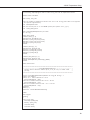
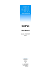
5.
If the CS225 temperature sensor addresses are unknown, then conduct a
query for each sensor’s current SDI-12 address with the “aI!” command.
If no characters are typed within 12 seconds, then the mode is exited. Once
a complete list of addresses is gathered you will know what block of
addresses are required in order to readdress the CS225. You will also be
able to request the related metadata so that sensor locations are confirmed.
Be sure to reference Table 7-4 for a list of appropriate addresses.
19
CS225 Temperature String
Figure 7—2 Screen capture of SDI-12 Transparent Mode on
CRBasic CR800 Datalogger using control port 1 and prompting for
SDI-12 addresses
6.
20
To change the SDI-12 address, press the <enter> key. At the “CR800>”
”CR1000>” prompt enter the command SDI-12 and press the <enter> key.
Enter the appropriate control port, press the <enter> key, and enter aAb!;
where a is the current address from the above step and b is the new
address. The temperature sensor will change its address and the datalogger
will respond with the new address and then exit the SDI-12 Transparent
Mode.
CS225 Temperature String
8. Maintenance and Calibration
The CS225 string requires no maintenance or calibration.
9. Troubleshooting
Symptom: -9999 or NAN for temperature
1.
Verify the green wire is connected to the control port specified by the
SDI12 measurement instruction.
2.
Verify the red power wire is connected to a 12V terminal; check the
voltage with a Digital Volt Meter. If a switched 12V terminal is used,
temporarily connect the red wire to a 12V terminal (non-switched) for test
purposes.
Symptom: Sensor won’t respond to command
1.
Expected address not used or has been changed.
a.
2.
In this case you may wish to confirm all addresses in use with the
“aI!” command in a trial & error fashion. You will be able to
determine the individual addresses of each temperature sensor.
Expected sensor address has been to match another sensor address already
in use.
a.
When readdressing temperature sensors you must avoid giving
multiple sensors the same address. If this does occur you will no
longer be able to communicate with these sensors. Use the
“aA{!” command, where “a” is the affected address. This will
reset the affected sensors to their factory configured address
value.
21
Campbell Scientific (Canada) Corp. | 14532 131 Avenue NW | Edmonton AB T5L 4X4 | 780.454.2505 | www.campbellsci.ca
AUSTRALIA | BRAZIL | CANADA | COSTA RICA | FRANCE | GERMANY | SOUTH AFRICA | SPAIN | UNITED KINGDOM | USA