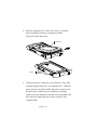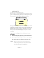
1
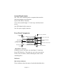
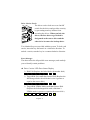
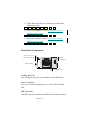
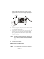
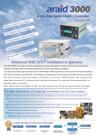
User’s Guide
Table of Contents
Welcome ....................................................................................................................... 4
Item Checklist.............................................................................................................. 5
Features and Benefits ................................................................................................. 5
System Requirements................................................................................................. 6
Front Panel Components ........................................................................................... 6
Indicators ................................................................................................................. 6
Disk Activity Indicators.................................................................................... 6
Disk Status / Rebuild Indicators...................................................................... 7
Rebuilding Activity / Error Message Indicator............................................ 7
Rebuilding Activity:.......................................................................................... 7
Drive Carrier Locks................................................................................................ 8
Error Message:................................................................................................... 8
Rear Panel Components ............................................................................................ 9
Cooling Fan Vent.................................................................................................... 9
Power Connector.................................................................................................... 9
IDE Connector........................................................................................................ 9
Master / Slave / Cable Select Jumper (JP1)..................................................... 10
Installation.................................................................................................................. 11
Mounting Controller Box in System................................................................. 11
Loading a Drive in the Drive Carrier................................................................ 12
Application 1: Two new disk drives (identical or non-identical)............ 15
Application 2: Installing one drive with data and one new backup
drive.................................................................................................................... 16
Online Rebuilding feature ....................................................................................... 18
Troubleshooting........................................................................................................ 21
English - 1
Contact Us.................................................................................................................. 24
Accusys-USA ........................................................................................................ 24
Accusys-Taiwan.................................................................................................... 24
Accusys-UK........................................................................................................... 24
Accusys-Germany ................................................................................................ 24
Accusys-Korea...................................................................................................... 24
English - 2
Product features and specifications described in this manual
are subject to change without notice.
Manufacturer shall not be liable for any damages, or for the
loss of information resulting from the performance or use of
the information contained herein.
All company and products names herein may be trademarks
or registered trademarks of their respective owners.
© 2002 All rights reserved.
English - 3
Welcome
Congratulations on your selection of the 7500. The 7500 are a
reliable and affordable solution for RAID 1 disk mirroring.
With a cost effective IDE approach, the 7500 mirrors data to
two disk drives simultaneously, and delivers optimized
performance, comparable to more costly SCSI based
solutions. If one drive fails, data is secured by the other drive
and alarm sounds to alert you.
Featuring intelligent online recovery, the 7500 lets you hot
swap a failed drive and the 7500 automatically rebuild the
data to the new drive without any system down time. The
7500 Controller Box features a user-friendly rack design that
lets you easily install a backup drive, or replace a drive that
fails. Each hard drive carrier supports a one-inch high 3.5inch form factor disk drive. Additional data security is
provided by a key-locking system, that prevents unauthorized
access to each disk drive.
7500 supports all hard disk manufacturer IDE hard drives that
confirm to the industry hard disk standard as IBM, Quantum,
Maxtor, Seagate, Samsung, and Fujitsu. 7500 also supports
Western Digital hard drive but please contact your 7500
supplier for necessary component. The location and distance
between IDE and Power connector in 7500 drive carriers
follow the specification in AT Attachment (ATAPI spec). The
IDE connector of the Western Digital disk drive has a 1-2 mm
alignment difference compared to drives of other brands.
Therefore, please specify before you ordering 7500 or contact
English - 4
your 7500 supplier for necessary component.
Item Checklist
The 7500 package contains the following items. Check that all
items listed here are present and in good condition. If anything
is missing or damaged, contact your vendor.
§ 7500 Controller Box
§ Two disk drive carriers with key locks
§ Disk drive mounting screws
§ User’s manual
§ Two keys (identical)
Features and Benefits
§
§
§
§
§
§
§
§
§
§
§
§
§
§
§
RAID level 1, disk mirroring
Fits into two 5 ¼” half-height drive bay
Automatic online rebuilding
IDE drives are hot swappable
Requires no software driver or add-in card
Supports Ultra ATA host interface
Supports 2 IDE hard drives
Can be configured as Master or Slave
Writes simultaneously to both drives
Host transparent and OS independent
Front panel operation indicators
Fan cooler (ball bearing type)
Audible alarm that works in conjunction with the
indicators alerting the user of failures
Battery backup memory for disk array status
Key locking to prevent unauthorized access to the disk
drives
English - 5
System Requirements
The 7500 can be installed inside a computer that meets the
following hardware specifications:
System with IDE/AT interface
Case with two half-height 5 ¼” drive bays with front bezel
access
One IDE channel cable connector
One free power supply connector
Front Panel Components
Disk activity indicators
Top drive
carrier
Top Drive carrier lock
Disk status / Rebuild
indicators
Rebuilding
activity / Error
message indicator
Bottom Drive carrier lock
Bottom drive
carrier
Disk activity indicators
About Drive Carriers :
Each drive carrier can hold a one-inch high 3.5-inch form
factor IDE disk drive. This makes it easy to hot swap a drive
in the event of a failure, without affecting the status of the
remaining drive.
Indicators
Disk Activity Indicators
These indicators show the status of each individual disk drive.
English - 6
Indicator
Green
Amber
Red
Disk Activity
Disk drive is properly installed and locked
Disk drive is being accessed
Disk drive is not present, is not properly
installed, is unlocked, or disk has failed
Note: Sometimes you can see the red disk activity LED
showing the 7500 is booting,
This is because the 7500 is searching for a disk, as soon
as it has found one, the red LED will turn off.
Disk Status / Rebuild Indicators
The upper indicator represents the top drive carrier, the lower
indicator represents the bottom drive carrier. If a drive fails,
the appropriate indicator turns on and an audible alarm sounds.
You can turn off the audible alarm by unlocking the drive
carrier.
The Indicator of the target disk will light up and blink while
rebuilding.
Rebuilding Activity / Error Message Indicator
Rebuilding Activity:
This row of eight indicators shows disks rebuilding activity.
In normal operation, a green light scans across the bank of
indicators. If you are using the online recovery feature to
rebuild a drive, all the indicators will turn on at the same time.
The left-side indicator blinks and then turns off when 12.5%
of the data has been mirrored. Then the next indicator blinks
and turns off when 25% of the data has been mirrored, and so
on.
English - 7
Drive Carrier Locks
The driver carrier lock acts as an On/Off
switch for the drives and provides security
by preventing non-key holders from
accessing the drives. When you lock the
drives, the first drive to get locked is
designated as the source drive and the
other drive becomes the backup drive.
Two identical keys are provided with the system. To lock each
carrier, insert the key and turn it in a clockwise direction. To
unlock a carrier, turn the key in a counterclockwise direction.
Error Message:
The chart offers the all-possible error messages, and can help
you to identify certain problems.
★ Drive Carriers LED Error Status Display
☆ Disk Fail (Replace the failed disk with another disk)
☆ Target Disk Size small than Source Disk (Replace the
failed target disk with a disk that’s size is greater or
equal to the source disk.)
☆ Target Disk UDMA Mode small than Source Disk
(Replace the failed target disk with a disk that’s
UDMA mode is greater or equal to the source disk.)
English - 8
☆ Target Disk has bad Sector (Replace the failed disk
with another disk)
☆ Power ON Channel 1 Fail (Call or email Accusys
product support center)
☆ Power ON Channel 2 Fail (Call or email Accusys
product support center)
Rear Panel Components
Master / Slave and
Cable Select Jumper
Power
connector
IDE connector
Cooling fan vent
Cooling Fan Vent
The cooling fan provides air circulation for the disk drives.
Power Connector
The power connector supplies power to the 7500 Controller
Box.
IDE Connector
The IDE connector connects to an IDE 80-pin interface ribbon
English - 9
cable.
NOTE: The cable has to meet the specification of UDMA66 and above.
Master / Slave / Cable Select Jumper (JP1)
This jumper allows the
3
2
1
user to set the 7500 up as
JP1
either an IDE Master,
Master / Slave / Cable
Select jumper
Slave, or Cable Select
device.
If the plastic jumper cap is placed on pins 2-3, the 7500 is set
as a Master device. If the jumper cap is completely removed
from the pins, the 7500 is set as a Slave device. If the jumper
cap is placed on pines 1-2, the 7500 is set as a Cable Detect
device, which means the system will automatically try to
identify the drive status.
Function
Master
Slave
Cable Select
JP1 Jumper Cap
Short pins 2-3
All pins free
Short pins 1-2
3 2 1
If there are two devices on a single IDE channel, one device
must be designated as Master and one device must be
designated as Slave or Cable Detect.
NOTE: Although the 7500 holds two IDE drives, your
computer treats the 7500 assembly as one single
drive. The drives inside the 7500 must be designated
English - 10
as Master devices.
Installation
Mounting Controller Box in System
CAUTION: Turn off and disconnect all electrical power from the system
before beginning any installation procedure.
1. Determine if you are installing the Controller Box as a
Master or Slave device. Remove the jumper cap from the
Master/Slave jumper if the Controller Box is a slave
device.
2. Remove the cover and front bezel from the system case.
3. Insert the 7500 Controller Box into the space of two halfEnglish - 11
height 5 ¼” drive bays, and secure it in place with the
screws provided. (If your case uses guide rails to install 5
¼ ” devices, you can use them on the Controller Box.)
IDE Socket
Power Cable
Pin 1
IDE Cable
Power Socket
4. Connect a free power cable to the power connector on the
rear side of the Controller Box.
5. Connect an IDE 80-pin ribbon cable connector to the IDE
connector on the rear side of the Controller Box. Make
sure the red stripe on the ribbon cable is aligned with pin 1
of the IDE connector.
NOTE: According to ATAPI specifications, please do not
use an IDE 80-pin ribbon cable longer than 46 cm
(18”).
6. Reassemble your computer.
Loading a Drive in the Drive Carrier
NOTE: 1. We recommend that you use identical disk drives in
English - 12
the two drive carriers. The hard disk drives must be
configured as Master devices.
2. 7500 supports the most models of the following
hard disk brands: IBM, Quantum, Maxtor, Seagate,
Samsung, and Fujitsu. 7500 also supports Western
Digital hard drive but please contact your 7500
supplier for necessary component.
1. Unlock the drive carriers and slide them out of the
Controller Box.
IDE connector
Drive carrier
Power connector
English - 13
2. Place the first disk drive in the drive carrier, so that the
power and IDE connectors correspond with the
connectors inside the carrier.
Disk drive
Screws
3. Connect the power connector to the disk drive first, then
carefully push the disk drive in so that the drive’s IDE and
power sockets seat into the IDE and power connectors in
the disk carrier. Make sure the connectors are firmly
seated, secure the disk drive with the screws provided, and
then slide the loaded disk drive carrier into the 7500
Controller Box.
English - 14
4. Repeat steps 1 to 3 for the second disk drive.
5. If you have installed two new disk drives go to
Application 1. If you have installed one drive with data
and one new disk drive go to Application 2.
Application 1: Two new disk drives (identical or non-identical)
1. Lock both drive carriers.
2. Turn on the computer system.
3. When the system prompts you to enter the BIOS setup
program shortly after power-on, follow the instructions
and enter the BIOS setup program. Set the hard disk drive
mode to “Auto”.
4. Save your changes to the BIOS setup program and reboot
the system. Your system is now ready to start using the
7500 and to automatically mirror all data written to it on
two disk drives.
5. If you have installed non-identical hard disk drives, your
computer will recognize the 7500 as a single hard disk
with a capacity equal to the smaller hard disk drive
English - 15
installed in the 7500.
The status of all indicators during boot-up:
Please be sure to put two hard disks into the two drive carriers
while the 7500 is booting, and lock it on before powering on.
Then you will see the indicators light up as follows:
ACS-7500
XXXXXXXXXXXXXXXXX
The green Disk Activity LED of the two drive carriers should
light up but the amber and red ones not; both Disk Status and
Rebuild LEDs should not light up; Rebuilding Activity and
Error Message LEDs should light up one by one as if it is
scanning.
Application 2: Installing one drive with data and one new
backup drive
1. The new backup drive must have the same capacity or a
larger capacity than the drive with data.
2. Lock the drive with data and leave the new drive unlocked.
This identifies the drive with data as the source drive.
NOTE: When you lock the drives, the first drive to get
locked is designated as the source drive and the
other drive becomes the backup drive.
English - 16
3. Turn on the computer system.
4. When the system prompts you to enter the BIOS setup
program shortly after power-on, follow the instructions
and enter the BIOS setup program. Set the hard disk drive
mode to “Auto”.
5. Save your changes to the BIOS setup program and reboot
the system.
6. After the boot process is complete, lock the new drive.
This identifies the new drive as the backup drive.
7. The system will immediately begin mirroring the data
from the first drive to the backup drive. Any old data on
the backup drive will be lost, and is overwritten with the
mirror image of the first drive.
Note: You need to repeat this procedure twice in order to
install a working Controller Box with a new pair of
larger drives without losing any data. The first step is
to mirror the data from the small hard drive, as source,
to a new larger hard drive, as target. The second step
is to mirror data from this new large hard drive, as
source, to a second large hard drive, as target. In this
case, you can omit steps 3, 4 and 5. However, under
DOS and Windows 3.1/95/98, you might not be able to
access the extra space if the existing data is stored in
an extended DOS partition. Under Windows NT, you
can use the Disk Administrator to create new
partitions in the extra space of larger drives.
English - 17
Online Rebuilding feature
The online Rebuilding feature allows you to hot swap a failed
disk drive with a new one, automatically recovering all data to
the new drive with no system down time. When the Controller
Box alerts you that a drive has failed, follow these
instructions.
1. Leave the system turned on. Unlock the carrier of the disk
drive that has failed and slide it out of the 7500 Controller
Box.
NOTE 1: The 7500 will continue to save data to the
remaining disk. No current or new data is lost while
you are replacing the failed drive.
2. Remove the failed disk drive from the carrier and install a
new one according to the instructions given above.
3. Slide the carrier with the new drive into the Controller
Box and lock it.
4. The system will immediately begin mirroring the data
from the first drive to the new drive. Any data on the new
drive is overwritten with the mirror image of the first
drive.
NOTE 2: When the 7500 is rebuilding the data and you shut
down the power, do not change any hard disks because
the 7500 will remember which disk is the source and
which is the target while rebuilding. It also keeps track
of the extent to which the data has been rebuilt. So if
English - 18
you change a hard disk in this situation, data error
could be the result. For example: If you change the
target hard disk in this situation, the 7500 will
continue rebuilding the data from where it left off so
that the first amount of data will not be stored on this
new target disk. That means the new disk will not have
the data that was already copied onto the hard disk
that was replaced.
NOTE 3: Before powering off while the7500 is rebuilding
data, don’t unlock the drive carrier that has the source
hard disk, and then power on again. This would result
in the two hard disks being rejected. If you have
already had this happen to you, unlock the both hard
disks before you power on the 7500, and wait till you
hear the beeper. After that, lock the source hard disk
and power on. Then lock in the target disk and the
7500 will begin rebuilding the data from the very start.
If you have already finished all these steps, please
follow the “Online Rebuilding” to copy the important
data to the target disk.
NOTE 4: If your source hard disk is a UDMA 100 disk and it
is smaller than the target disk, you can use the 7500 to
copy the data on the source disk to the target disk. The
function works the same as the “Online rebuding”, but
the transfer rate remains UDMA 100 instead of
UDMA 133.
English - 19
NOTE 5: When the power disconnected when rebuilding, the
7500 will continue the data rebuilding when the power
returns, instead of rebuilding from the beginning. It is
because there is a build-in battery inside 7500; it
offers the memory on rebuilding status when the power
is interrupted. Under normal application the battery
will work for around 3 years. If necessary, please
replace with the same type of battery and read
carefully the use instruction on the battery. Please
follow the original installation when replacing the
new battery.
CAUTION
RISK OF EXPLOSION IF BATTERY IS REPLACED BY
AN INCORRECT TYPE.
DISPOSE OF BATTERIES ACCORDING TO THE
BATTERY’S INSTRUCTION.
English - 20
Troubleshooting
If you encounter a problem while installing or using 7500,
check this section for help.
1. I cannot connect a Western Digital hard drive into the
connectors of the drive carrier.
There is a specially designed drive carrier for the
Western Digital disk drive. Please specify before you
ordering.
The location and distance between IDE and Power
connector in 7500 drive carriers follow the specification in
AT Attachment (ATAPI spec). The IDE connector of the
Western Digital disk drive has a 1-2 mm alignment
difference compared to drives of other brands.
7500 supports hard disk drives from Fujitsu, IBM, Maxtor,
Quantum, Seagate, Samsung and Western Digital.
2. When I lock the first drive carrier with a disk drive in
place, the red disk activity indicator turns on and an
alarm beep sounds.
(a) Make sure you firmly connect the IDE and Power
connectors of hard disk to the ir counterparts inside the
drive carrier and try again. If this does not solve the
situation, go to (b)
(b) Change the disk drive with a new one and try again.
(c) Exchange the top and bottom drive carriers and try
again.
(d) If all of the above steps fail, contact your vendor.
English - 21
3. When I lock the second drive carrier with a disk drive
in place, the red activity indicator turns on and an
alarm beep sounds (The first Drive Carrier has already
been locked without any problem).
(a) Make sure you firmly connect the IDE and Power
connectors of hard disk to the ir counterparts inside the
drive carrier and try again. If this does not solve the
situation, go to (b)
(b) Check if the capacity of the second disk drive is equal
or bigger than the first one.
(c) Change the disk drive with a new one and try again.
(d) Exchange the top and bottom drive carriers and try
again.
(e) If all of the above steps fail, contact your vendor.
4. I locked only one of the two hard disks when powering
on the 7500, and then lock the other one while the 7500
is without power. After that, the drive carrier that was
locked last can’t be used normally. How do I solve this
problem?
Lock the both hard disks when powering on the 7500
and wait for the buzzer sound. After that, lock the drive
carrier that has source hard disk and power on. If you have
already finished all these steps, please follow the “Online
rebuilding” to copy the important data to the target disk.
5. I shut down the power while the 7500 was rebuilding,
and I also keyed off the drive carrier with the source
English - 22
disk. I then discover both disks are rejected and I hear
the beeper when I power on the 7500 again. How do I
solve this problem?
The 7500 can’t ascertain user’s action without power.
But when in operation, it always remembers that status of
the work. For example: which disk is source, which one is
target, and the extent the data or only has one hard disk.
The 7500 will remember this situation while it’s
rebuilding data or only has one hard disk. (Of course, the
7500 has to be powered up if it is to remember this
situation) If the 7500 detects a situation that is different
from before, it will reject the hard disk that has created the
different situation. If you already had this happen to you,
please unlock both hard disks when powering on the 7500,
and wait for the beeper. After that, please lock the drive
carrier that has the source hard disk, and power on. This
allows the 7500 to recognize the new disk as source or
target, depending upon which disk as been changed. If you
have already completed all steps, please follow the
“Online rebuilding” to copy the important data to the
target disk.
6. How can I turn off the alarm beep sound when there is
a hard disk failure?
Unlock the drive carrier of the failed disk. This will
turn off the alarm beep sound.
7. I use a 60 cm IDE cable to connect the 7500, but the
system shows some error messages and the hard drive
English - 23
can’t be accessed normally.
The 7500’s specifications are based on ATAPI
specifications. To ensure good IDE signal quality, the
length of your IDE cable cannot be longer than 46 cm (18
inch).
Contact Us
Accusys-USA
E-mail: [email protected];
[email protected]
Web Site: http://www.accusysusa.com
Toll free number: +1-866-277-5888
Accusys-Taiwan
E-mail: [email protected]; [email protected]
Web Site: http://www.accusys.com.tw
Tel: +886-3-575-0668
Accusys-UK
E-mail: [email protected]
Web Site: http://www.accusys.co.uk
Tel: +44-1293-400-521
Accusys-Germany
E-mail: [email protected]
Web Site: http://www.accusys.co.de
Tel: +49-89-374-0760
Accusys-Korea
E-mail: [email protected]
English - 24
Web Site: http://www.accusys.co.kr
Tel: +82-2-6245-9050
Specifications are subject to change
without notice!
English - 25