1
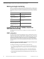
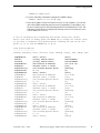
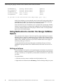
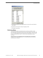
*071-8471-00*
Monitoring the QLogic SANbox Fibre
Channel Switch with NetCentral
Table of Contents
P
re
lim
in
ar
y
Before you begin monitoring .................................................................................. 2
Configuring the QLogic SANbox Switch for NetCentral monitoring ..................... 2
SNMP configuration .......................................................................................... 2
Using NetCentral to monitor the QLogic SANbox Switch ...................................... 4
Setting port aliases............................................................................................. 4
Monitoring Status............................................................................................... 5
Monitoring Trends ............................................................................................. 7
Troubleshooting with NetCentral....................................................................... 8
Copyright © 2005 Thomson Broadcast and Media Solutions, Inc. All rights reserved. Printed in the United States of America.
This document may not be copied in whole or in part, or otherwise reproduced except as specifically permitted under U.S. copyright law, without the prior written consent of
Thomson Broadcast and Media Solutions, Inc.., P.O. Box 59900, Nevada City, California 95959-7900
Grass Valley, Profile and Profile XP are either registered trademarks or trademarks of Thomson Broadcast and Media Solutions, Inc. in the United States and/or other countries. Other trademarks used in this document are either registered trademarks or trademarks of the manufacturers or vendors of the associated products. Thomson Broadcast
and Media Solutions, Inc. products are covered by U.S. and foreign patents, issued and pending. Additional information regarding Thomson Broadcast and Media Solutions,
Inc.s trademarks and other proprietary rights may be found at www.thomsongrassvalley.com.
Product options and specifications subject to change without notice. The information in this manual is furnished for informational use only, is subject to change without notice,
and should not be construed as a commitment by Thomson Broadcast and Media Solutions, Inc.. Thomson Broadcast and Media Solutions, Inc. assumes no responsibility or
liability for any errors or inaccuracies that may appear in this publication.
Monitoring the QLogic SANbox Fibre Channel Switch with NetCentral
Before you begin monitoring
Before you can monitor a QLogic SANbox Fibre Channel Switch, you must prepare
the QLogic SANbox Fibre Channel Switch and the NetCentral system. The required
tasks and the documents in which you can find instructions are listed in the following
table:
Using the following documentation:
Install the QLogic SANbox Fibre
Channel Switch
SANbox Fibre Channel Switch
Installation Guide
Assign an IP address to the
QLogic SANbox Fibre Channel
Switch
Grass Valley Fibre Channel Switch
Installation Manual
Set up the NetCentral system
NetCentral User Guide and NetCentral
Release Notes
P
re
lim
in
ar
y
Do this...
Install the QLogic SANbox Fibre
Channel Switch device provider
License the QLogic SANbox
Fibre Channel Switch device
provider
NetCentral Release Notes
Configuring the QLogic SANbox Switch for
NetCentral monitoring
The following section describes how to configure your switch for operation with
NetCentral.
SNMP configuration
The QLogic SANbox Switch has a SNMP agent, which is a standard software item on
all QLogic SANbox Switches. SNMP includes a mechanism to report events as soon
as they occur, rather than waiting until a device is polled to obtain its status. This type
of notification is called a trap, and can be sent to one or several SNMP managers.
When you monitor with NetCentral you want traps sent to the NetCentral manager
software component, so you set the trap destination to the IP address of the NetCentral
server PC.
NOTE: You can also perform the SNMP configuration using the SANsurfer switch
management application via the Ethernet network.
To configure the destination for trap notifications, follow these steps:
1. Use Telnet over the Ethernet LAN or a serial communication application such as
Hyperterminal through an RS-232 connection to enter access the Command Line
Interface.
2. Log in to the switch with administrator permissions. The default administrator
account is username admin and password password, all in lowercase characters.
3. Type the following command to enter the administrator mode, which allows you to
modify settings:
2
Monitoring the QLogic SANbox Fibre Channel Switch with NetCentral
Preliminary July 7, 2005
SNMP configuration
SANbox #> admin start
4. Type the following command to configure the SNMP settings:
SANbox (admin) #> set setup snmp
5. Enter the IP address for the NetCentral server PC as Trap1Address. You can also
enter other SNMP monitoring stations in turn (Trap2Address, Trap3Address, etc.).
Be sure to enable traps for each monitoring station (Trap1Enabled set to True). The
following example shows a configuration with traps sent to a NetCentral server PC
with IP address 10.16.43.18:
P
re
lim
in
ar
y
A list of attributes with formatting and current values will follow.
Enter a new value or simply press the ENTER key to accept the current value.
If you wish to terminate this process before reaching the end of the list
press 'q' or 'Q' and the ENTER key to do so.
Trap Severity Options
--------------------unknown, emergency, alert, critical, error, warning, notify, info, debug, mark
SnmpEnabled
Contact
Location
Trap1Address
Trap1Port
Trap1Severity
Trap1Version
Trap1Enabled
Trap2Addres
Trap2Port
Trap2Severity
Trap2Version
Trap2Enabled
Trap3Address
Trap3Port
Trap3Severity
Trap3Version
Trap3Enabled
Trap4Address
Trap4Port
Trap4Severity
Trap4Version
Trap4Enabled
Trap5Address
Trap5Port
Trap5Severity
Trap5Version
Trap5Enabled
Preliminary July 7, 2005
(True / False)
(string, max=64 chars)
(string, max=64 chars)
(dot-notated IP Address)
(decimal value, 1-65535)
(see allowed options above)
(1 / 2)
(True / False)
(dot-notated IP Address)
(decimal value, 1-65535)
(see allowed options above)
(1 / 2)
(True / False)
(dot-notated IP Address)
(decimal value, 1-65535)
(see allowed options above)
(1 / 2)
(True / False)
(dot-notated IP Address)
(decimal value, 1-65535)
(see allowed options above)
(1 / 2)
(True / False)
(dot-notated IP Address)
(decimal value, 1-65535)
(see allowed options above)
(1 / 2)
(True / False)
[True]
[ContactName]
[LocationName
[10.16.43.18]
[162]
[warning]
[2]
[True]
[0.0.0.50]
[162]
[warning]
[2]
[False]
[0.0.0.0]
[162]
[warning]
[2]
[False]
[0.0.0.0]
[162]
[warning]
[2]
[False]
[0.0.0.0]
[162]
[warning]
[2]
[False]
Monitoring the QLogic SANbox Fibre Channel Switch with NetCentral
3
Monitoring the QLogic SANbox Fibre Channel Switch with NetCentral
ReadCommunity
WriteCommunity
TrapCommunity
AuthFailureTrap
ProxyEnabled
(string, max=32 chars)
(string, max=32 chars)
(string, max=32 chars)
(True / False)
(True / False)
[public]
[public]
[public]
[True]
[True]
Do you want to save and activate this snmp setup? (y/n): [n] y
In this list of attributes you can optionally enter Contact and Location strings that are
meaningful to NetCentral users at your site. If your site uses an SNMP community
name other than “public”, you can also set the community name.
P
re
lim
in
ar
y
Your NetCentral server PC should now receive all traps from your QLogic SANbox
Switch. You can test this by creating a fault condition, such as disconnecting one of
your Fibre Channel connections to the QLogic SANbox Switch. A message should
appear in the NetCentral manager.
Using NetCentral to monitor the QLogic SANbox
Switch
This section describes features of the NetCentral IV product (NetCentral version 4.1
and higher) that are specific to monitoring a QLogic SANbox Fibre Channel Switch.
These features are added to the NetCentral Manager interface only when the QLogic
SANbox Fibre Channel Switch device provider is installed and so do not apply to
monitoring other types of devices.
To understand NetCentral features that apply to monitoring all types of devices,
including the QLogic SANbox Fibre Channel Switch, refer to the NetCentral User
Guide.
Setting port aliases
You can configure NetCentral to set the reporting name of each port on your QLogic
SANbox Switch to something meaningful to you. When NetCentral reports the status
of a port, or notifies you of a problem, you may find it convenient to see a name that
you chose
To set port aliases:
1. Select the switch you want to configure in the NetCentral tree view.
2. Right-click the switch and select Port Settings. The Port Settings dialog box opens.
4
Monitoring the QLogic SANbox Fibre Channel Switch with NetCentral
Preliminary July 7, 2005
P
re
lim
in
ar
y
Monitoring Status
3. Select the Port Alias for a port. When selected, a text entry box opens. Enter the
desired alias.
4. Repeat the previous step for each port requiring an alias.
5. Click OK to set the aliases.
Monitoring Status
You can use NetCentral to monitor the status of your QLogic SANbox Switch.
NetCentral displays information about the switch’s power supplies, temperature, and
fans. Click on the appropriate subsystem node in the NetCentral tree view to monitor
its status. Consult the NetCentral User Guide for more information on using
NetCentral.
NetCentral also lets you monitor the status of each of the ports on your QLogic
SANbox Switch. Click the Ports node to view information such as the state and
transmitter type of each port.
Preliminary July 7, 2005
Monitoring the QLogic SANbox Fibre Channel Switch with NetCentral
5
P
re
lim
in
ar
y
Monitoring the QLogic SANbox Fibre Channel Switch with NetCentral
You can also view configuration events. Select the Events subsystem node to see a
summary of the configuration events on the switch.
6
Monitoring the QLogic SANbox Fibre Channel Switch with NetCentral
Preliminary July 7, 2005
Monitoring Trends
Monitoring Trends
Click the NetCentral Trends view control button to view graphs of status parameters.
The following table specifies the parameters reported in the Trends view:
Parameter Name
Comments
Unit
System\Up Time
Up time essentially is an ever incrementing value that indicates the system is up and
running and is measured as an absolute value in minutes; given that the polling rate is
more than a minute.
Minutes
P
re
lim
in
ar
y
Though the value itself is of less significance, it is the ramp graph obtained by plotting
these values that proves significant where a downward edge on the ramp indicates a
device going offline and a flat line at zero indicating the device downtime.
Multiple ramps indicate how often the device was taken down for activities like
maintenance or servicing, or simply how many times it was restarted to handle a
complete device failure. If the ramps do not coincide when the device was taken down,
it could indicate conditions like automatic restarts, and the device may need attention.
System\Processor
Usage
Processor Usage is the average percentage of elapsed time that the processor spends
executing non-idle instructions during that sampling period and is an indicator of
switch management activity.
%
Sustained value over 80% (5 minutes or more) indicates an excessively busy system
and may result in the system appearing unresponsive to management applications.
Upper Threshold: 80
System\Memory
Usage
Memory usage is the percentage of total physical memory used by the system during
that sampling period to support switch management operations.
%
Sustained increase in this value could indicate a memory leak in one or more running
programs, or high system loading and might eventually lead to system failure due to
unavailability of more memory.
Upper Threshold: 90
Ports\Throughput
[module-port]
Throughput is the rate at which data is transmitted or received at a switch port in Mega
Bits per second during that sampling period.
Mega Bits
Per Second
(Mbps)
This is an indicator of the port usage
Ports\Link
Failures
[module-port]
Link failures indicate the number of times the Fibre Channel connectivity with the port
was “broken” during that sampling interval when the port observes errors for a
sustained time interval and was online.
Errors
This is likely an indicator for a faulty connector or cable. These are also caused when
the device connected to the port is restarted, replaced or being serviced when the Fibre
Channel cable connected to the port is temporarily disconnected.
The error recovery for this type of error is disruptive and will be noticed by the device
connected to the port. Each such error will cause the system to run degraded until the
link recovery is complete.
Preliminary July 7, 2005
Monitoring the QLogic SANbox Fibre Channel Switch with NetCentral
7
Monitoring the QLogic SANbox Fibre Channel Switch with NetCentral
Parameter Name
Comments
Unit
Ports\Sync Losses
[module-port]
Sync Losses indicates the number of times the port went into the “loss of
synchronization” state where it encountered continuous Disparity errors during that
sampling interval.
Errors
This is likely an indicator for a faulty connector or cable. These are also caused when
the device connected to the port is restarted, replaced or being serviced when the Fibre
Channel cable connected to the port is temporarily disconnected.
If the port is in the “loss of synchronization” state for longer than a specific period, the
port will get into the link failure state which could degrade the performance of the
Fibre Channel link.
Signal losses is the number times the port detected a loss of the electrical or optical
signal used to transfer data on the port during that sampling period.
P
re
lim
in
ar
y
Ports\Signal
Losses
[module-port]
Errors
This is likely an indicator for a faulty connector or cable. These are also caused when
the device connected to the port is replaced or being serviced when the Fibre Channel
cable connected to the port is temporarily disconnected.
If the port is in the “loss of signal” state for longer than a specific period, the port will
get into the link failure state which could degrade the performance of the Fibre
Channel link.
Ports\CRC Errors
[module-port]
CRC Errors is the number of Fibre Channel frames handled by the port that containing
checksum errors during that sampling period. Typically the error is recovered by
retransmitting the frame and the error will go unnoticed by the device connected to the
port.
Errors
These are usually recoverable errors and will not degrade system performance unless
their occurrence is sustained when the data cannot be relayed after retransmissions.
Troubleshooting with NetCentral
NetCentral reports status, warnings, and alarms using messages that are easy to
understand. Suggested corrective actions are presented along with failure
information. If you have any trouble interpreting any of the problems or suggested
solutions, contact Grass Valley support.
8
Monitoring the QLogic SANbox Fibre Channel Switch with NetCentral
Preliminary July 7, 2005