1
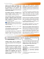
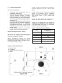
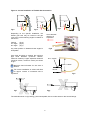
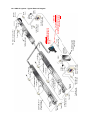
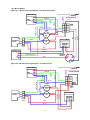
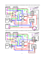
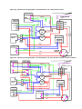
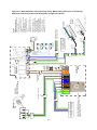
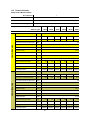
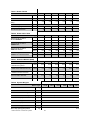
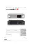
Instruction Manual
NOR-RAY-VAC CONTINUOUS
RADIANT TUBE SYSTEM
INSTALLATION INSTRUCTION
INDEX
MANUAL
Section
Installation Requirements ------------------------------------------------ 1
User and Operating Instructions ---------------------------------------- 2
WARNINGS
AmbiRad equipment must be installed and maintained in accordance with the relevant
provisions of the Gas Safety (Installations and Use) Regulations 1998 for gas fired products.
Due account should also be taken of any obligations arising from the Health and Safety at
Works Act 1974 or relevant codes of practice. In addition the installation must be carried out
in accordance with the current IEE wiring regulations (BS 7671), BS 6896 (Industrial &
Commercial) and any other relevant British Standards and Codes of Practice by a qualified
installer. All external wiring MUST comply with the current IEE wiring regulations.
Part No. 700052
AmbiRad Limited, Fens Pool Avenue, Brierley Hill, West Midlands, DY5 1QA
Document Index.
1 Installation Requirements
1.1 Health & Safety
1.2 Burner Model Definitions
1.3 Heater Suspension
1.4 Clearance to Combustibles
1.5 Gas Connection & Supply Details
1.6 Electrical Connections
1.6.1 Typical Wiring Schematic
1.6.2 Wiring Details
1.7 Ventilation Requirements
1.8 Exhaust & Air Inlet Options
1.8.1 Exhaust Flue Considerations
1.8.2 Ducted Air Inlet Considerations
1.9 Vacuum Fan Details
1.10 Technical Data
2
User and Operating Instructions
2.1 To Start Heater
2.2 To Switch Off Heater
2.3 Routine Maintenance Between Service Intervals
2.4 Frequency of Servicing
Introduction.
Welcome to the range of Nor-Ray-Vac ‘LR’
series continuous radiant tube heaters. The
Nor-Ray-Vac ‘LR’ series system complies with
the requirements of the European Gas
Appliance Directive BS EN777-4. Local
regulations may vary in the country of use and it
is the installers responsibility to ensure that such
regulations are satisfied.
number of radiant branches manifolded
together, linked by a tail pipe to a vacuum fan
discharging the spent products of combustion to
atmosphere. A system may comprise of just one
burner and one vacuum fan, to multiple burners
in multiple radiant branches with one or more
vacuum fans.
To enable exact matching of operational needs
within an area, distances between burners and
ratings of the burners can vary. The unique
feature of Nor-Ray-Vac ‘LR’ series is a radiant
system which provides uniform heat coverage of
the floor area, eliminating hot/cold spots.
All installation, assembly, commissioning and
service procedures must be carried out by
suitable qualified competent persons to the
statutory regulations in the country of use.
When assembling, installing, commissioning and
servicing is undertaken on radiant tube heaters
specified in these instructions, due care and
attention is required to ensure that working at
height regulations are adhered to at the
mounting heights specified.
The tube into which the burners are mounted
and over which the reflectors are fitted and
emits the maximum heat is called the radiant
tube. The radiant heat emitted from the hot tube
is directed downwards by reflectors. The
remaining interconnecting tube is called the tail
pipe and radiates with less intensity.
PLEASE READ this document prior to
installation to familiarise yourself with the
components and tools you require at the various
stages of assembly.
The operating temperatures of the tubes
generally range from 200°C – 480°C max.
All Dimensions shown are in mm unless
otherwise stated.
The action of the vacuum fan is three fold; to
create a high negative pressure within the
radiant tube and tail pipe so as to discharge the
spent products of combustion from the system
to a point outside the building being heated; to
control the flow of gas and air through each
burner in stoichiometric proportions; to draw
carrier air into the tube system at the start of
each radiant branch, in order to distribute the
heat from the flame along the tube.
The manufacturer reserves the right to alter
specifications without prior notice.
The Ambi-Rad Nor-Ray-Vac ‘LR’ series direct
gas fired radiant heating system comprises of a
continuous system with a number of burners
located in series in a radiant branch, and a
1. Installation Requirements.
Isolate any electrical supply to the heater and controller before proceeding.
1.1
The system is assembled at high level
suspended by chains from first fixings to
the roof structure.
(First fixings by others)
Health and Safety
AmbiRad heaters must be installed in
accordance with the relevant provisions of the
Gas Safety (Installations and Use) Regulations
1998.
For your own safety we recommend the use of
safety boots and leather faced gloves when
handling sharp or heavy items. The use of
protective eye wear is also recommended.
Due account should also be taken of any
obligations arising from the Health and Safety
at Works Act 1974 or relevant codes of
practice. In addition the installation must be
carried out in accordance with the current IEE
wiring regulations (BS 7671), BS 6896:
(Industrial & Commercial) and any other
relevant British Standards and Codes of
Practice by a qualified installer. Isolate all
electrical supplies to the heater & controller
before proceeding.
1.2
Burner Model Definitions
NRVxxLR-EV
= Nor-Ray-Vac continuous
radiant tube heater only for use with branch end
configurations.
NRVxxLR-IL
= Nor-Ray-Vac continuous
radiant tube heater only for use with in-line
configurations.
xx denotes kW rating. Models available; 12, 18,
24, 32, 38 and 46
3
1.3
1.3.2.3 A support must always be located at a
maximum distance of 2m from a tee or elbow
fitting.
Heater Suspension
1.3.1 First considerations
•
•
•
•
1.3.2.4 Except for the combustion chamber
support lug suspension points, suspension
support brackets are installed to support the
tube section which is then covered with
reflectors.
Clearances from combustibles must be
maintained. (See figure 2)
For ease of servicing there should be a
minimum clearance distance of 500mm
between the burners of the heating system
and the building wall. This measurement
can be reduced for perimeter type systems.
(See figure 1a).
For ease of servicing and burner removal
minimum clearances should be maintained.
(See figure 1b and 1c). In exceptional
circumstances the burner lid may be slid
diagonally for removal thus reducing the
vertical distance.
Ensure that the suspension is sufficiently
flexible to allow for thermal expansion.
1.3.2.5 Tail pipe hangers are installed for the
tube section which will be without reflectors.
If there are any doubts as to the strength or
suitability of roof steelwork to which heaters are
to be suspended, please refer to a Consultant,
Architect or owner of the building.
Table 1. Minimum mounting heights
1.3.2 Suspending the heater - General
1.3.2.1 The first support is always positioned at
the support lug suspension point on the end
vent burner combustion chamber.
1.3.2.2 Subsequent supports are placed
approximately 2.8m apart, including one at each
combustion chamber location. This gives a maximum load per support of 24kg.
Figure 1.a Overall Dimensions
A - Burner Tube
B - LR Burner
C - Optional Perimeter Reflector
D - Wall
(100mm MIN - Perimeter Systems)
4
Model
Minimum Mounting
Heights (m)
NRV12LR
3.0m
NRV18LR
3.6m
NRV24LR
4.0m
NRV32LR
4.7m
NRV38LR
5.3m
NRV46LR
6.0m
Figure 1.b Clearance for servicing - distances to walls and obstacles above.
G
Figure 1.c Clearance for servicing - distances to obstacles above.
E - Obstacle over burner
F - End vent module
G - Burner lid
E
G
5
1.4
Clearance to Combustibles.
The minimum clearances to combustible materials are given in table 2 below. These minimum
distances MUST be adhered to at all times.
Figure 2 Diagram illustrating the clearance to combustibles
Distance from combustibles (distance from heat source that will produce a 50ºC rise in temperature above ambient of a
black surface) A Radiant tube; B Standard reflector; C Combustible material underneath; D Combustible material on side;
E Combustible material above; F Perimeter reflector;
Table 2
Burner Model
NRV12LR
NRV18LR
NRV24LR
End vent
In-line
End vent
In-line
End vent
In-line
1120
1250
1120
1250
1120
1250
760
850
760
850
760
850
Below tube
Dim D Without undershield mm
Dim D With undershield
mm
Dim C Above Tube
mm
250
Horizontally
Dim B Standard reflector
mm
600
770
600
770
600
770
Dim A Perimeter reflector
mm
305
450
305
450
305
450
Burner Model
NRV32LR
NRV38LR
NRV46LR
End vent
In-line
End vent
In-line
End vent
1440
1700
1570
2100
1700
2100
760
850
785
1050
850
1050
Below tube
Dim D Without undershield mm
Dim D With undershield
mm
Dim C Above Tube
mm
250
Horizontally
Dim B Standard reflector
mm
700
850
700
1000
700
1000
Dim A Perimeter reflector
mm
305
6 510
305
600
305
600
1.5
Gas Connection and Supply
Take care when making a gas connection
to the heater not to apply excessive turning
force to the internal controls.
Before installation, check that the
local distribution conditions, nature of
gas and pressure, and adjustment of
the appliance are compatible.
A flexible hose is installed to allow safe linear
expansion to each burner without creating
undue stress on the gas supply pipe work. It is
therefore important that a tested and certified
hose assembly made to ISO 10380, supplied
with ½” BSP female cone seat adapters, is
installed as per these instructions.
A competent or qualified engineer is required to
either install a new gas meter to the service
pipe or to check that the existing meter is
adequate to deal with the rate of gas supply
required.
Installation pipes should be fitted in accordance
with BS 6896, so that the supply pressure, as
stated in Table 3 will be achieved. It is the
responsibility of the competent engineer to
ensure that other relevant Standards and
Codes of Practice are complied with in the
country of installation.
It is also important to ensure that expansion is
taken up in the body of the flexible hose, and
not on its attachment to the pipe work.
The cone seat adapter supplied on one end of
the flexible gas hose provides a `swivel` action,
and must be fitted on the burner using a ½”
BSP barrel nipple to provide ease of
disconnection for future servicing.
Pipes of smaller size than the heater inlet gas
connection must not be used. The complete
installation must be tested for soundness as
described in the country of installation.
The installation layout described below is
the only method recommended by the
institute of gas engineers, the hose
manufacturer, and AmbiRad and must only be
carried out by a qualified/competent gas
engineer.
The gas union service cock MUST be
fitted in the gas supply close to the heater, but not onto the burner itself.
Table 3 Gas Supply Pressures
G20
G25
G30
G31
Natural Gas
Natural Gas
Butane
Propane
Max Supply Pressure (mbar)
50
50
35
57.5
Min Supply Pressure (mbar)
17.5
20
20
25
20
25
29
37
Gas Category
Gas Type
Nominal Pressure (mbar)
Gas Supply
Connection R½ ½in BSP Internal Thread
7
Figure 3. Correct Installation of Flexible Gas Connection
x
fig.b
fig.a
Depending on the specific installation, the
flexible gas hose may be routed to the gas
cock at any of the following angles in relation to
the burner:
Vertical
45° angle
90° angle
fig.c
x
Arrow denotes
direction of
expansion.
(fig.a)
(fig.b)
(fig.c)
fig.d
Any other position in between these angles is
acceptable.
Care must be taken to observe the minimum
pipe bend diameter (minimum 250mm,
maximum 350mm) & pipe expansion distance
(minimum 30mm, maximum 70mm) as shown
in fig.e.
50 +/- 20mm
400 +/- 50mm
Maximum bend diameter for the hose is
450mm.
Burner
The correct installation as shown will allow
for approx 100mm of movement due to
expansion.
fig.e
fig.f
fig.g
The methods shown in fig.f and fig.g are unacceptable, due to undue stress on the hose & fittings.
8
1.6
Electrical Connections
should be of 0.5mm²
minimum and comply
with BS 6500. For fan
and LRU supply, the wire
size must be suitable for
the current ratings as
listed in Table 10.
Standard burner 16W.
Current rating 0.05 amp per burner
Fuse: external 3 amp.
Each component carrying an electrical
supply must be earthed.
Supply for burners is 230V 50Hz single
phase.
* Exhaust fans are three phase 415V
50Hz.
* IP54 rated Inverter panel LRU’s require
a 230V single phase supply at 22A (B80/
B160) or 30A (B300)
* Standard LRU’s require a 415V three phase
supply at 25A (BH300)
The wires in the mains
lead are coloured in
accordance with the
following code: Green &
Yellow
Earth;
Blue
Neutral; Brown Live
The method of connection to the electrical
supply must facilitate complete isolation and
should be via a fused double pole isolator
having contact separation of at least 3mm on all
poles and supplying the appliance only.
* refer to individual site specifications
All electrical work should be carried out to IEE
standards by a competent electrician.
The electrical connection to the burner is made
by means of a three pin plug-in power
connector. Live, neutral and earth connections
should be made via a flexible supply cable to
the power connector and routed clear of the
heater or tubes.
We recommend use of AmbiRad approved
controls. Please refer to; SmartCom control
manual for siting and installation details and
figures 4.l and 4.m
Where alternative controls are used, please
refer to the manufactures instructions for their
siting and installation details.
The flexible supply cables to each burner
Figure 4.a. Typical Wiring Connections
To other
in-line burners
Fused Spur
In-line
Burner
‘Power out’ from
End Vent Burner to
In-line Burner(s)
End Vent
Burner
Fused Spur
230V 50Hz
Switched Supply
from Control Source
9
10
In-line Burner
To ‘Mains In’ on
End Vent Burner
230V 50Hz 13A
Mains Supply
End Vent
Module
SmartCom³ no.1
‘Master’ (SC3-MZ)
Isolator
0.75mm²
Screened
Cable
Sensor
Zone 1
Isolator
Networking Cable
Screened pair Beldon
9841 or equiv
* 4 core
Armoured Cable
End Vent
Burner
0.75mm²
Screened
Cable
* IMPORTANT
For Inverter Panels only
(fan types B80/B160 & B300)
MAXIMUM length of cable between
Inverter and Fan is 5m.
Sensor
Zone 2
Fused
Spur
End Vent
Module
SmartCom³ no.2
‘Slave’ (SC3-MZ)
230V 50Hz 13A
Mains Supply
Isolator
IMPORTANT
Fan types B80/B160 & B300)
MOTOR MUST BE WIRED IN
DELTA.
Tail Pipe
Local Relay
Unit / Inverter
Panel
In-line Burner
Fused Spur
1st Branch Zone 1
In-line Burner
Fused Spur
From ‘Power out’
on End Vent Burner
to In-line Burners
Fused Spur
End Vent
Burner
Fused Spur
To ‘Mains In’ on
End Vent Burner
Fused Spur
End Vent
Module
End Vent
Burner
From ‘Power out’ on
End Vent Burner to
In-line Burners
2nd Branch Zone 1
In-line Burner
Fused Spur
1st Branch Zone 2
In-line Burner
Fused Spur
From ‘Power out’ on End Vent
Burner to In-line Burners
1.6.1 NRV LR system - Typical External Diagram
1.6.2 Wiring Details
Figure 4.c. LR internal wiring diagram - End Vent Burner (EV)
MAINS INPUT
IGNITOR
GRN/YEL
8
12
3
7
11
2
10
1
9
MAIN
J.S.T.
RED
MAINS
ON
4
DELAY TIMER
BURNER
ON
BLACK
BLUE
2
BROWN
LAMPS
BLACK
GREY
3
BLUE
BLUE
BLUE
GREEN/YELLOW
BROWN
N
FLAME SENSOR
RED
EMC
FILTER
SOLENOID
VALVE
PURPLE
L
1
5 4 3 2 1
VALVE
J.S.T.
RED
BLUE
POWER OUT
BLUE
N
GREEN/YELLOW
VACUUM
SWITCH
RED
N.O.
L
C.
N.C.
Figure 4.d. LR internal wiring diagram - In-line Burner (IL)
MAINS INPUT
IGNITOR
N
BLUE
BURNER
ON
1
VALVE
J.S.T.
RED
BLUE
11
4
8
12
3
7
11
10
1
9
RED
2
MAIN
J.S.T.
DELAY TIMER
BROWN
2
MAINS
ON
BROWN
3
SOLENOID
VALVE
LAMPS
BLUE
GREEN/YELLOW
BLUE
FLAME SENSOR
5 4 3 2 1
BLACK
GRN/YEL
BROWN
EMC
FILTER
PURPLE
L
Figure 4.e. LR internal wiring diagram - End Vent Burner c/w N/O or N/C volt free Lockout contacts
EMC FILTER
IGNITOR
PURPLE
L3
GRN/YEL
BROWN
RELAY
N.C.
A1
Detail shows
either N.O. or
N.O. contacts
A2
3
SOLENOID
VALVE
LAMPS
BLUE
2
BLUE
BLUE
MAINS
ON
4
8
12
3
7
11
2
10
1
9
MAIN
J.S.T.
RED
C.
BLUE
L1
GREEN/YELLOW
N.O.
BROWN
L2
BLACK
DELAY TIMER
BURNER
ON
BLACK
N
FLAME SENSOR
GREY
MAINS INPUT
1
VALVE
J.S.T.
5 4 3 2 1
RED
RED
BLUE
POWER OUT
BLUE
N
GREEN/YELLOW
VACUUM
SWITCH
RED
L
N.O.
C.
N.C.
Figure 4.f. LR internal wiring diagram - In-line Burner c/w N/O or N/C volt free Lockout contacts
EMC FILTER
IGNITOR
PURPLE
L3
GRN/YEL
RELAY
N.O.
A2
3
2
LAMPS
MAINS
ON
BURNER
ON
1
VALVE
J.S.T.
RED
RED
BLUE
12
4
8
12
3
7
11
2
10
1
9
RED
A1
Detail shows
either N.O. or
N.O. contacts
BLUE
MAIN
J.S.T.
DELAY TIMER
BROWN
N.C.
BLUE
C.
BLUE
GREEN/YELLOW
L1
BROWN
L2
SOLENOID
VALVE
BROWN
N
FLAME SENSOR
5 4 3 2 1
BLACK
MAINS INPUT
Figure 4.g. LR internal wiring diagram - End Vent Burner c/w 3 way solenoid valve
MAINS INPUT
IGNITOR
PURPLE
LAMPS
MAINS
ON
BLUE
2
4
8
12
3
7
11
2
10
1
9
MAIN
J.S.T.
DELAY TIMER
BURNER
ON
BLACK
3
SOLENOID
VALVE
BROWN
BLUE
RED
1
BLUE
BLUE
BLUE
2
GREEN/YELLOW
3 WAY AR
SOLENOID
BLACK
GREY
BROWN
N
FLAME SENSOR
RED
GRN/YEL
EMC
FILTER
RED
L
1
5 4 3 2 1
VALVE
J.S.T.
RED
BLUE
POWER OUT
BLUE
N
GRN/YEL
VACUUM
SWITCH
RED
L
N.O.
C.
N.C.
RED
Figure 4.h. LR internal wiring diagram - End Vent Burner c/w valve & N/O or N/C VF Lockout contacts
EMC FILTER
IGNITOR
PURPLE
GRN/YEL
BROWN
N
C.
N.C.
A1
BLUE
BLUE
LAMPS
A2
3
SOLENOID
VALVE
2
4
8
12
3
7
11
2
10
1
9
MAIN
J.S.T.
BLUE
MAINS
ON
BLACK
BLUE
GREY
L1
BROWN
N.O.
GRN/YEL
RELAY
L2
FLAME SENSOR
DELAY TIMER
BURNER
ON
1
VALVE
J.S.T.
5 4 3 2 1
RED
RED
3 WAY AR
SOLENOID
BLUE
GRN/YEL
2
BLUE
POWER OUT
N
1
BLUE
GRN/YEL
RED
L
RED
13
VACUUM
SWITCH
N.O.
C.
N.C.
BLACK
L3
RED
MAINS INPUT
Figure 4.j. NRV Inverter Internal Wiring Diagram for B80, B160 and B300 three phase fans
E L
R/L1
15V
0V AI1
RC
Fan Trip
Circuit
t3
tW
tV TO FAN
tU
FAN HEALTHY LAMP
t4
Brown
VF Enable
Circuit
t2
W/T3
V/T2
U/T1
Brown
t1
Brown
N
LI1
Violet
3Ph Supply
To Fan
S/L2
V.S.D.1
Orange
230V 50Hz
1 Ph Supply
L
Blue
Brown
Green/Yellow
MAINS ON LAMP
RA
E
N
230V 50HZ 1 Pha SUPPLY
A1
11
A2
12
1 2 3 4
E E L L N N
U V W
TERMINAL RAIL
Figure 4.k. NRV Local Relay Unit Internal Wiring Diagram for BH300 three phase fans
E L3 L2 L1
N
415V 50HZ 3 Pha SUPPLY
MAINS ON LAMP
t1
N
A2
3Ph Supply
To Fan
97
96
13
A1
t4
t3
Fan Trip
Circuit
L3 L2 L1
98
Brown
E
14
Contactor
Brown
415V 50Hz
3 Ph Supply
95
VF Enable
Circuit
3
2
1
t2
1 2 3 4
E E L3 L2 L1 L1 N N
U V W
14
TERMINAL RAIL
6
4
2
tU
tV TO FAN
tW
Blue
Brown
Black
Grey
Green/Yellow
FAN HEALTHY
15
4-Core Armoured or
Screened Cable 1.5mm²
MPORTANT
For Inverter panels only
(fan types B80 / B160 & B300):
MAXIMUM length of cable between inverter
and fan is 5m (EMC class A building) or
10m (EMC class B building).
N.B. if in doubt, do not exceed 5m.
230V 1P 22A
230V 1P 22A
230V 1P 30A
B80
B160
B300
THE LOCAL RELAY UNIT houses an inverter. This
converts the 230V single-phase input into a
three-phase 230V output. The inverter provides a
soft start to the motor, which extends the motor life
by minimising the start current.
ELECTRICAL INPUT
FAN TYPE
SUPPLY VIA ISOLATOR
3 Phase
Isolator
L
L
N N
U
(FAN CIRCUIT)
2
40
C
3
4
Volt free
Fan Trip
Indication
by others
9
Inverter
Local Relay
Unit
V W 1
Low Voltage
+15V DC
!
41
(FAN CIRCUIT)
5
6
!
LIVE
1/L 2/N
(LIVE)
NEUT
(NEUTRAL)
SmartCom
Singlezone
10
eg Door
Drawing No. : 900287 R6
Burners
Zone A
Supply to inline
burners
*The power supply is non-isolated,
therefore all wiring to the control must be
mains rated.
REMOTE SENSOR(s) may be
placed at a max distance of 100m
from the control unit, using
screened 6A mains* cable.
Wiring should be kept separate
from mains wiring to minimise
noise pick up. Set within Engineers
functions for remote sensor.
*The power supply is non-isolated,
therefore all wiring to the control must be
mains rated.
REMOTE SWITCH INPUTS
should be connected by 6A mains
Max length is 100m.
Low voltage switching inputs to be
normally open (closed circuit to
enable).
Connect to B0 & B1 for remote ON
(ie BMS time control).
Connect to B0 & B2 for remote
OFF (ie door interlock. remote
frost etc).
NOTES:
230V 50Hz 1 Pha
Supply via Isolator
Black Bulb
Sensor
Note: Connection to the
burners MUST be made
via a 3A fused spur.
(where applicable)
Remote ON
eg B.M.S.
(where applicable)
Remote OFF
B1 B0 B2 S/R0S/R1
(COMMON)
FAN MOTOR
230V 3-Phase Supply.
Motor must be wired DELTA
(REMOTE ON)
FUSE RATING
!
(REMOTE OFF)
Exhaust
Fan
Figure 4.l. NRV Schematic interconnecting wiring. B80, B160 and B300 three phase fans
controlled by SmartCom3 via single phase Inverter panel. (single zone shown)
(HEAT 1 OUTPUT)
16
415V 3P 25A
BH300
FAN MOTOR
415V 3-Phase Supply.
Motor must be wired DELTA
L3 L2 L1 L1 N
4-Core Armoured Cable
THE LOCAL RELAY UNIT houses a 3pha
motor contactor and overload plus any
additional fan logic circuitry.
ELECTRICAL INPUT
FAN TYPE
SUPPLY VIA ISOLATOR
3 Phase
Isolator
Exhaust
Fan
N
U
1
2
40
(FAN CIRCUIT)
(FAN CIRCUIT)
C
3
4
Volt free
Fan Trip
Indication
by others
9
Local Relay
Unit
V W
Mains Voltage
230V AC
!
41
5
6
!
1/L 2/N
(NEUTRAL)
(LIVE)
LIVE
10
eg Door
Drawing No. : 900289 R8
Burners
Zone A
Supply to inline
burners
*The power supply is non-isolated,
therefore all wiring to the control must be
mains rated.
REMOTE SENSOR(s) may be
placed at a max distance of 100m
from the control unit, using
screened 6A mains* cable.
Wiring should be kept separate
from mains wiring to minimise
noise pick up. Set within Engineers
functions for remote sensor.
*The power supply is non-isolated,
therefore all wiring to the control must be
mains rated.
REMOTE SWITCH INPUTS
should be connected by 6A mains
Max length is 100m.
Low voltage switching inputs to be
normally open (closed circuit to
enable).
Connect to B0 & B1 for remote ON
(ie BMS time control).
Connect to B0 & B2 for remote
OFF (ie door interlock. remote
frost etc).
NOTES:
230V 50Hz 1 Pha
Supply via Isolator
Black Bulb
Sensor
Note: Connection to the
burners MUST be made
via a 3A fused spur.
(where applicable)
Remote ON
eg B.M.S.
(where applicable)
Remote OFF
B1 B0 B2 S/R0S/R1
(COMMON)
NEUT
(REMOTE ON)
SmartCom
Singlezone
(REMOTE OFF)
FUSE RATING
!
Figure 4.m. NRV Schematic interconnecting wiring. BH300 three phase fans controlled by
SmartCom3 via three phase Local Relay panel. (single zone shown)
(HEAT 1 OUTPUT)
17
*The power supply is non-isolated,
4-Core Armoured or
Screened Cable 1.5mm²
230V 1P 22A
230V 1P 22A
230V 1P 30A
B80
B160
B300
THE LOCAL RELAY UNIT houses an inverter. This
converts the 230V single-phase input into a
three-phase 230V output. The inverter provides a
soft start to the motor, which extends the motor life
by minimising the start current.
ELECTRICAL INPUT
FAN TYPE
L
L
N N
U
!
41
(FAN CIRCUIT)
2
40
(FAN CIRCUIT)
3
9
Inverter
Local Relay
Unit
V W 1
therefore all wiring to the control must be
MPORTANT
mains rated.
For Inverter panels only
(fan types B80 / B160 & B300):
MAXIMUM length of cable between inverter
Low Voltage
and fan is 5m (EMC class A building) or
+15V DC
10m (EMC class B building).
N.B. if in doubt, do not exceed 5m.
SUPPLY VIA ISOLATOR
3 Phase
Isolator
NOTES:
REMOTE SENSOR(s) may be
placed at a max distance of 100m
from the control unit, using
screened 6A mains* cable.
Wiring should be kept separate
from mains wiring to minimise
noise pick up. Set within Engineers
functions for remote sensor.
4
C
5
(HEAT 1 OUTPUT)
6
1/L 2/N
10
Note:
Connection to the
burners MUST
be made via a
3A fused spur.
!
LIVE
(LIVE)
NEUT
(NEUTRAL)
SmartCom
Singlezone
230V VBurner ON Signal
230V 50Hz 1 Pha
Supply via Isolator
Black Bulb
Sensor
Volt Free Burner Lockout
Circuit
Volt Free Remote ON
Circuit
Volt Free Fan Trip Circuit
Drawing No. : 900287 R6 LO
Burners
Zone A
THE SOFTWARE FOR THE BMS MUST ONLY REQUEST A
LOCKOUT CONDITION WHEN THE SYSTEM IS
REQUESTING HEAT. IN ADDITION, IT SHOULD ALSO
PROVIDE A 60s DELAY BEFORE INDICATING LOCKOUT.
THIS IS TO ALLOW THE SOLENOID COIL TO OPERATE
AFTER INITIAL SUPPLY IS CONNECTED TO THE HEATER,
WHEN CALLING FOR THE HEAT VIA THE CONTROL
SYSTEM AND A RE-START ATTEMPT IF NECCESARY
Note: If the point is not complied with the BMS
will receive a false report of the burner status
B1 B0 B2 S/R0S/R1
(COMMON)
FAN MOTOR
230V 3-Phase Supply.
Motor must be wired DELTA
(REMOTE ON)
Exhaust
Fan
(REMOTE OFF)
FUSE RATING
!
Volt
Free
BMS
Figure 4.n. NRV Schematic interconnecting wiring. B80, B160 and B300 three phase fans
controlled by SmartCom3 via single phase Inverter panel. Zonal BMS Lockout and VF interface.
18
*The power supply is non-isolated,
4-Core Armoured or
Screened Cable 1.5mm²
230V 1P 22A
230V 1P 22A
230V 1P 30A
B80
B160
B300
THE LOCAL RELAY UNIT houses an inverter. This
converts the 230V single-phase input into a
three-phase 230V output. The inverter provides a
soft start to the motor, which extends the motor life
by minimising the start current.
ELECTRICAL INPUT
FAN TYPE
L
L
N N
U
!
41
(FAN CIRCUIT)
2
40
(FAN CIRCUIT)
3
9
Inverter
Local Relay
Unit
V W 1
therefore all wiring to the control must be
MPORTANT
mains rated.
For Inverter panels only
(fan types B80 / B160 & B300):
MAXIMUM length of cable between inverter
Low Voltage
and fan is 5m (EMC class A building) or
+15V DC
10m (EMC class B building).
N.B. if in doubt, do not exceed 5m.
SUPPLY VIA ISOLATOR
3 Phase
Isolator
NOTES:
REMOTE SENSOR(s) may be
placed at a max distance of 100m
from the control unit, using
screened 6A mains* cable.
Wiring should be kept separate
from mains wiring to minimise
noise pick up. Set within Engineers
functions for remote sensor.
4
C
5
(HEAT 1 OUTPUT)
6
1/L 2/N
10
Note:
Connection to the
burners MUST
be made via a
3A fused spur.
!
LIVE
(LIVE)
NEUT
(NEUTRAL)
SmartCom
Singlezone
B1 B0 B2 S/R0S/R1
(COMMON)
FAN MOTOR
230V 3-Phase Supply.
Motor must be wired DELTA
(REMOTE ON)
Exhaust
Fan
(REMOTE OFF)
FUSE RATING
!
230V VBurner ON Signal
Volt Free Burner Lockout
Circuit Burner #3
Volt Free Burner Lockout
Circuit Burner #2
Volt Free Burner Lockout
Circuit Burner #1
Volt Free Remote ON
Circuit
Volt
Free
Drawing No. : 900287 R5 LOM
Burners
Zone A
THE SOFTWARE FOR THE BMS MUST ONLY REQUEST A LOCKOUT
CONDITION WHEN THE SYSTEM IS REQUESTING HEAT. IN ADDITION,
IT SHOULD ALSO PROVIDE A 60s DELAY BEFORE INDICATING
LOCKOUT. THIS IS TO ALLOW THE SOLENOID COIL TO OPERATE
AFTER INITIAL SUPPLY IS CONNECTED TO THE HEATER, WHEN
CALLING FOR THE HEAT VIA THE CONTROL SYSTEM AND A
RE-START ATTEMPT IF NECCESARY.
Note: If the point is not complied with
the BMS will receive a false
report of the burner status.
230V 50Hz 1 Pha
Supply via Isolator
Black Bulb
Sensor
Volt Free Fan Trip Circuit
BMS
Figure 4.p. NRV Schematic interconnecting wiring. B80, B160 and B300 three phase fans
controlled by SmartCom3 via Inverter panel. Individual BMS burner Lockout and VF interface.
1.8.2 Vertical discharge
1.7 Ventilation Requirements
Nor-Ray-Vac heaters are installed as flued
appliances in accordance with the relevant
national requirements in the country of
installation.
In buildings having an air change rate of less
than 0.5 per hour, additional ventilation is
required. For detailed information, please see
BS6896 section 5.2.2.2.1
Natural Ventilation
Low level ventilation openings with a free area
of at least 2cm²/kW shall be provided. See
BS6896 section 5.2.2.2.2.1.
1.8
Exhaust and Air Inlet - Options
1.8.1 Horizontal discharge
Considerations.
The vacuum fan must be located as
shown in the layout drawing.
The vacuum fan must have a bottom horizontal discharge.
The fan should be fitted to the mounting
platform which is fixed to the wall or
building structure. Alternatively, the fan
can be suspended from the roof
structure, via drop rods (not supplied) and
mounted on base frame. (Anti-vibration
mountings are fitted between the fan and
the mounting platform/base frame.
For full details of parts and installation,
please refer to section 2.9.3
19
1.8.3 Ducted Air Inlet Considerations.
Ensure that the flexible ductwork is installed to
allow for expansion of the heating system.
Heat resistant flexible tube is connected to the
burner assembly ducted air adaptor and the
EVM ducted air adaptor and connected to the
air supply duct
On a header duct, the main air supply header
which is feeding the individual branch ducts and
burner/end vent supply ducts must have a
maximum pressure drop of 0.25 mbar (0.1in
wg).
The maximum length of 100mm diameter
ductwork is 2m.
All joints and seams in the air supply system
must be made air tight and a bird screen used at
the inlet.
Ensure that the flexible supply duct does not
drape over or touch the reflector.
For full details refer to section 2.13
Figure 5.a. Header Duct Connection
Ø100 Duct to burner
Ø100 Duct to EVM
500mm MIN
Figure 5.b.
End Vent Ducted
Air Inlet Connection
Figure 5.c.
Burner Ducted
Air Inlet Connection
20
(For heater duct
Directly above system)
Main header Duct
Ø150 for LR12-24
Ø200 for LR32-46
450mm MIN
Branch Duct
Ø100 for LR12-24, Ø150 for LR32-46
1.9 Vacuum fan mounting details (Type ‘B160’ fan illustrated)
Fan Size
B80
B160
B300
BH300
A (crs)
216
276
286
324
B
595
595
625
704
C
305
308
330
352
D
580
555
575
650
E (Ø)
150
152
152
152
50
97
50
50
G (Ø)
150
150
150
148
H
295
318
340
380
J
80
90
90
110
K
150
140
140
120
L
240
240
240
240
M
309
303
341
404
N
50
62
157
157
P
421
463
616
680
R (crs)
318
318
318
318
S (crs)
356
356
356
356
T
204
204
204
204
V
115
115
115
115
X
21
36
46
84
F
21
1.10 Technical Details.
Tables 4a & b Burner Details
No of Injectors
1
Gas Connection
½ in BSP Internal thread
Burner current
0.05 (per burner)
Electrical Voltage/Ph/Hz
230 volt 1 phase 50Hz
Burner Type
12LR
18LR
24LR
32LR
38LR
46LR
Burner Details
Gas Category
II
G20 Natural Gas
Heat input (Gross)
kW
12
18
24
32
38
46
Gas consum rate Nat Gas G20
m³/h
1.14
1.72
2.29
3.05
3.62
4.38
Max Inlet pressure Nat Gas G20
mbar
50
Min Inlet Pressure Nat Gas G20
mbar
17.5
Hs Nat Gas G20
MJ/m³
37.78
Hi Nat Gas G20
MJ/m³
34.02
d Nat Gas G20
0.555
Ws Nat Gas G20
MJ/m³
50.72
Wi Nat Gas G20
MJ/m³
45.67
Injector size Nat Gas G20
mm
Injector Part No.
Air shutter size Nat Gas G20
3.6
4.4
4.9
5.4
5.8
6.3
L100336 L100544 L100549 L100554 L100558 L100563
mm
Air shutter Part No.
13
17
19.5
22.0
24.0
26.5
L100322 L100321 L100320 L100314 L100316 L100318
Gas Category
II
G25 Natural Gas
Heat input (Gross)
kW
12
18
24
32
38
46
Gas consum rate Nat Gas G25
m³/h
1.33
1.99
2.66
3.55
4.21
5.10
Max Inlet pressure Nat Gas G25
mbar
50
Min Inlet Pressure Nat Gas G25
mbar
20
Hs Nat Gas G25
MJ/m³
32.49
Hi Nat Gas G25
MJ/m³
29.25
d Nat Gas G25
0.612
Ws Nat Gas G25
MJ/m³
41.52
Wi Nat Gas G25
MJ/m³
37.38
Injector size Nat Gas G25
mm
Injector Part No.
Air shutter size Nat Gas G25
Air shutter Part No.
3.7
4.6
5.2
5.8
6.3
6.9
L100537 L100546 L100552 L100558 L100563 L100569
mm
13
17
19.5
22.0
24.0
26.5
L100322 L100321 L100320 L100314 L100316 L100318
22
Tables 4c & d Burner Details
Burner Type
12LR
18LR
24LR
32LR
38LR
46LR
Burner Details
Gas Category
III
G30 Butane Gas
Heat input (Gross)
kW
12
18
24
32
38
46
Gas consum rate Butane G30
m³/h
0.34
0.52
0.69
0.92
1.09
1.32
Max Inlet pressure Butane G30
mbar
35
Min Inlet Pressure Butane G30
mbar
20
Hs Butane G30
MJ/m³
125.81
Hi Butane G30
MJ/m³
116.09
d Butane G30
2.075
Ws Butane G30
MJ/m³
87.33
Wi Butane G30
MJ/m³
80.58
Injector size Butane G30
mm
Injector Part No.
Air shutter size Butane G30
2.6
3.2
3.7
4.2
4.6
5.1
L100526 L100532 L100537 L100542 L100546 L100551
mm
Air shutter Part No.
13
17
19.5
22.0
24.0
26.5
L100322 L100321 L100320 L100314 L100316 L100318
Gas Category
III
G31 Propane Gas
Heat input (Gross)
kW
12
18
24
32
38
46
Gas consum rate Propane G31
m³/h
0.45
0.68
0.90
1.21
1.43
1.73
Max Inlet pressure Propane G31
mbar
57.5
Min Inlet Pressure Propane G31
mbar
25
Hs Propane G31
MJ/m³
95.65
Hi Propane G31
MJ/m³
88.00
d Propane G31
1.55
Ws Propane G31
MJ/m³
76.84
Wi Propane G31
MJ/m³
70.69
Injector size Propane G31
mm
Injector Part No.
Air shutter size Propane G31
2.9
3.5
4.0
4.4
4.8
5.2
L100529 L100535 L100540 L100544 L100548 L100552
mm
Air shutter Part No.
13
17
19.5
22.0
24.0
26.5
L100322 L100321 L100320 L100314 L100316 L100318
Hs = Gross CV
Hi = Net CV
Ws = Wobbe number on gross CV
Wi = Wobbe number on net CV
d = specific density
Reference gas conditions = dry, 15ºC 1013 mbar
23
Table 5. Heater Details
Burner Type
12LR
18LR
24LR
32LR
38LR
46LR
Min distance between burners
m
5.2
7.4
9.4
14
18
23
Max distance between burners
m
7.2
10.2
13.1
18
23
27
Min distance between burner and
fitting
m
3.6
3.6
5.0
6.0
7.0
8.0
Max tube temp
°C
Min mounting height
m
450
480
3.0
3.6
4.0
4.7
5.3
6.0
5
4
3
3
3
3
Burner Type
12LR
18LR
24LR
32LR
38LR
46LR
db(A)
tba
tba
37
tba
tba
tba
NR±2
tba
tba
33
tba
tba
tba
db(A)
tba
tba
tba
tba
tba
tba
NR±2
tba
tba
tba
tba
tba
tba
db(A)
tba
tba
tba
36
tba
tba
NR±2
tba
tba
tba
33
tba
tba
db(A)
tba
tba
tba
37
tba
tba
NR±2
tba
tba
tba
34
tba
tba
Burner Type
12LR
18LR
24LR
32LR
38LR
46LR
End vent setting (hot)
- Multi burner systems
mbar
6.25
6.25
6.25
6.25
6.25
6.25
End vent setting (hot)
- SINGLE End Vent burners only
mbar
n/a
n/a
n/a
7.5
8.25
9.25
End vent setting (hot)
- THREE burners in a branch
mbar
n/a
n/a
n/a
n/a
n/a
5.6
mm
14.5
16
24
27
32
n/a
L104102
L104101
L104100
L104093
L104092
n/a
Max burners per branch
Table 6. Heater Noise Data
Noise level @ 3m below
In-Line BURNER
Noise level @ 3m below
EVM Burner
Noise level @ 3m below
EVM with silencer
Noise level @ 3m below
EVM Burner with Ducted Air
Table 7. End Vent Module (EVM)
End Vent orifice diameter
End Vent orifice Part No.
Table 8. System Weights
Burner Type
LR Burner
12LR
18LR
24LR
32LR
38LR
46LR
kg
8.3
Radiant branch*
kg/m
8.3
Radiant branch + Slimline grille*
kg/m
10.9
Radiant branch + Protective guard*
kg/m
10.0
4” Mild steel tail pipe
kg/m
5.5
4” Aluminum tail pipe
kg/m
0.9
6” Mild steel tail pipe
kg/m
10.6
6” Aluminium tail pipe
kg/m
1.3
kg
24.2
Max / susp point @ EV position
* without burners or ducted air systems
24
Table 9. Fan Details
Fan Size
B80
B160
B300
BH300
201760
201761
201762
201763
QS 80M2B H
QS 90S2A-40H
QS 90L2A H
QS 112M2A H
kW
1.1
1.5
2.2
4.0
V/Hz/P
230~50/3
230~50/3
230~50/3
400~50/3
Run Current
A
4.38
5.6
8.48
7.2
Start Current
A
n/a
n/a
n/a
54.0
RPM
2850
2860
2840
2880
Inverter
∆
∆
∆
Fan part number
Motor (TEE)
Power
Supply to Fan
Speed
Wired
D.O.L.
∆
Flow rate @ 20°C
m³/h
368
736
1380
1380
Flow rate @ 150°C
m³/h
259
519
972
972
Pressure
mbar
29
29
29
42
Max Operating Temp.
°C
200
200
200
200
Weight
kg
45
52
58
75
Fan Size
B80
B160
B300
BH300
900274
900088
900089
900282
kW
1.5
1.5
2.2
n/a
V/Hz/P
230~50/1
230~50/1
230~50/1
400~50/3
Line Current
A
14.8
14.8
20.8
n/a
Motor Current
A
4.2
5.6
7.8
7.2
Fuse Rating
A
22
22
30
n/a
Acceleration Time
s
25
25
25
n/a
Deceleration Time
s
25
25
25
n/a
Table 10. Local Relay Unit
LRU part number
Inverter type
Supply to LRU
Table 11. Fan Noise Data
Noise level @ 3m below fan
Noise level @ 3m below fan
with motor muff
Noise level @ 3m below
in acoustic enclosure
Fan Size
B80
B160
B300
BH300
db(A)
63
64
65
68
NR±2
57
58
59
62
db(A)
62
63
64
66
NR±2
56
57
58
60
db(A)
51
53
55
58
NR±2
45
47
49
52
db(A)
69
72
75
77
NR±2
63
66
69
71
db(A)
56
57
58
58
NR±2
50
51
52
52
Flue horizontal/vertical @ 3m
Flue horizontal/vertical @ 3m
With exhaust silencer
25
Notes.
Notes.
2. User & Operating Instructions.
To Start the Heater
2.3
1. Ensure that gas supply is turned on at
each burner.
After ensuring that the heater is cold and
mains electric isolated, cleaning of the
reflectors with a soft cloth and a mild
detergent (non solvent based cleaners only)
in water can be undertaken.
2. Switch on electrical supply to heaters.
3. Ensure that the controls are correctly set
i.e.;
•
•
•
5 If the lighting up sequence fails and lockout
occurs press the lockout reset button (if
available), or switch off the electrical
supply and restart after 40 seconds. If
lockout occurs three times consecutively
switch off and isolate the gas and
electricity supplies.
Contact the AmbiRad Service department.
2.2.
Additional removal of dust from the radiant
tubes, burner and heat exchanger can be
undertaken.
Clock is correctly set.
Heater program is correctly set.
Required room temp is correctly set
4. The vacuum fan will operate and at the
same time the red neon lights will
illuminate at all burners. After 10 seconds
the burners closest to the exhaust fan in
each radiant branch will light, with both red
and amber neons illuminated. After a
further 25 seconds the next burner in line
within each radiant branch will light and
after a further 25 seconds the end vent
burner will light.
To Switch Off Heater
1. Switch off electrical supply to the heater.
The burner will stop and the fan will shut
off.
2. If the heater is to be switched off for
periods in excess of one week it is highly
recommended that both the gas and the
electrical supplies are turned off.
Routine Maintenance between Service
Intervals
2.4
Frequency of Servicing
The manufacturer recommends that to
ensure continued efficient and safe
operation of the appliance, the heater is
serviced annually by a competent person
e.g. every year in normal working conditions
but in exceptional dusty or polluted
conditions more frequent servicing may be
required.
The manufacturer offers a maintenance
service.
Details are available on request.
For Service requirements, please contact
AmbiRad.
For further technical and service support
visit our Support Information Database at
www.s-i-d.co.uk
Note This notice must be fixed alongside the
electrical service switch. On some systems only
the end vent burner contains a delay timer. In
this instance the inline burners will light
simultaneously and the end vent burners will
light after an 80 seconds delay.
Technical Support:
Tel: 01384 489 200
Fax: 01384 489 707
[email protected]
www.ambiradgroup.co.uk
Document reference number GB/NRV/193I/0314
2.1