1
Appendix E: High-speed Input and Pulse Output Features
1
2
3
4
E
6
7
8
9
10
11
12
13
14
A
B
C
D
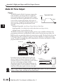
Mode 20: Up/Down Counter
Purpose
The counter in the HSIO circuit can count up/down signals from two separate sources (i.e.,
two single channel encoders) or two quadrature signal pulses. Quadrature signals are
commonly generated from incremental encoders, which may be rotary or linear. The
up/down counter has a range from -8388608 to 8388607. Using CT174 and CT175, the
quadrature counter can count at up to a 7 kHz rate.
NOTE: The count is 32 bit BCD sign + magnitude format.
Functional Block Diagram
E–24
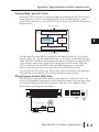
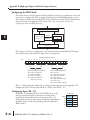
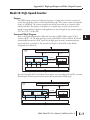
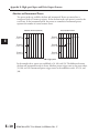
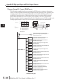
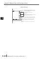
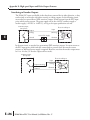
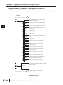
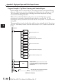
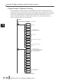
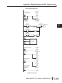
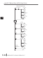
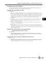
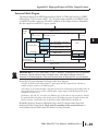
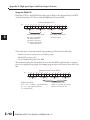
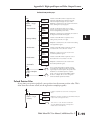
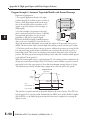
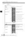
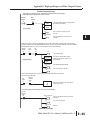
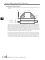
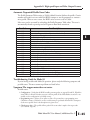
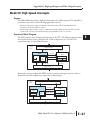
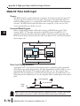
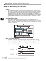
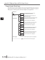
The diagram below shows HSIO functionality in Mode 20. When the lower byte of HSIO
Mode register V7633 contains a BCD “20”, the up/down counter in the HSIO circuit is
enabled. For quadrature counting, input X0 is dedicated to the Phase A quadrature signal,
Output Circuit
DL06
PLC
Y2 - Y17
Y0 - Y1
HSIO
I/O data
Counter
Phase A
Phase B
X0
Reset
X1
X2
Mode Select
Filter
X3
CPU
V-memory
V7633
0020
X4 - X23
Input Circuit
and input X1 receives Phase B signal. X2 is dedicated to reset the counter to zero value when
energized.
Output Circuit
DL06
PLC
Y2 - Y17
Y0 - Y1
HSIO
I/O data
Counter
Up
X0
Down
X1
Reset
X2
Filter
Mode Select
X3
CPU
V-memory
V7633
0020
X4 - X23
Input Circuit
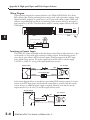
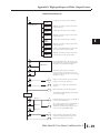
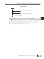
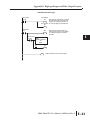
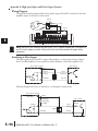
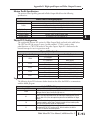
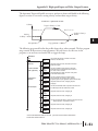
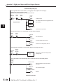
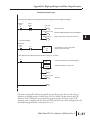
For standard up/down counting, input X0 is dedicated to the up counting signal, and input
X1 is dedicated to the down counting signal. The X2 input resets the counter to zero when
energized.
DL06 Micro PLC User Manual, 3rd Edition, Rev. C