1
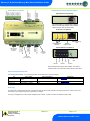
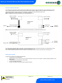
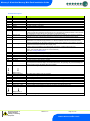
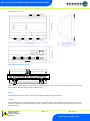
Intuitive Mercury Network Expansion Options
Relay 4 Common
Relay 4 N/O
Relay 4 N/C
Transducer
Ground
Input 5
Ground
Input 4
Ground
Input 3
Ground
Input 2
Ground
Input 1
Ground
Intuitive Mercury Controller
Relay 5 Common
Relay 5 N/O
Relay 5 N/C
Mercury 2 & Intuitive Mercury Mini-Pack Installation Guide
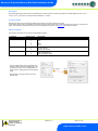
RS232 Network Card (Default)
The Intuitive Mercury is supplied with an RS232
Network Card fitted as standard. Some example
optional network cards are shown below
IP Network Card (PR0770)
Relay 1 N/C
Relay 1 N/O
Relay 1 Common
Relay 2 N/C
Relay 2 N/O
Relay 2 Common
Mains Supply
100-240vAC
50-60Hz
Relay 3 N/C
Relay 3 N/O
Relay 3 Common
N
N/C
L
Rotary Address
Switches
Network
Collision LED
Network Activity
LED
RS485 Network Card (PR0771)
Network
Expansion
Port
Not Fitted
(For future use)
Network Activity
LED
A+
BGround
Ground
Screen
PR0772 Wireless Mesh Option also available. The network
interfaces work in the same way as there external counterparts.
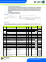
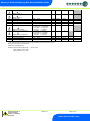
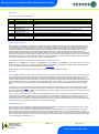
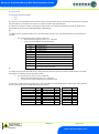
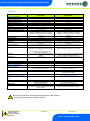
Input and Output Allocation Table
The following tables indicate; on a controller type basis, the functions of the inputs and outputs.
I/O
Stage Inputs 1-5
Transducer Input
Relays 1-5
Type 1 Pack
Status Input or Temperature
Probe
Pressure Transducer
Compressor or Loader
Type 2 Condenser
Status Input or Temperature Probe
Comments
See Status Input
Pressure Transducer
Fan
See Interface Board
Wire to N/O Contacts
Alarm relay
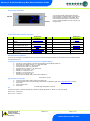
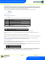
The alarm relay is assigned automatically to the first free relay that has not been utilised in the stage programming. At first power on this
will be Relay 1 until programming of the output stage is complete.
The relay is energised with no alarm and de-energised when in alarm. Any alarm condition will activate the alarm relay.
Warning
Ensure that all power is
switched off before
installing or maintaining
this product
Revision 1.5
Page 5 of 19
www.resourcedm.com
Please Note