1
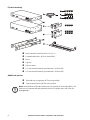
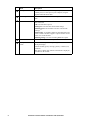
Installation and Quick Start Rack Automatic Transfer Switch This manual is available in English on the enclosed CD. Dieses Handbuch ist in Deutsch auf der beiliegenden CD-ROM verfügbar. Este manual está disponible en español en el CD-ROM adjunto. Ce manuel est disponible en français sur le CD-ROM ci-inclus. Questo manuale è disponibile in italiano nel CD-ROM allegato. 本マニュアルの日本語版は同梱の CD-ROM からご覧になれます。 Instrukcja Obsługi w jezyku polskim jest dostepna na CD. O manual em Português está disponível no CD-ROM em anexo. Данное руководство на русском языке имеется на прилагаемом компакт-диске. Bu kullanim kilavuzunun Türkçe'sä, äläxäkte gönderälen CD äçeräsände mevcuttur. 您可以从包含的 CD 上获得本手册的中文版本。 Contents Preliminary Information.................................................. 1 Overview . . . . . . . . . . . . . . . . . . . . . . . . . . . . . . . . . . . . . . . . . . . . . . . . 1 Additional documentation . . . . . . . . . . . . . . . . . . . . . . . . . . . . . . . . . 1 Receiving inspection . . . . . . . . . . . . . . . . . . . . . . . . . . . . . . . . . . . . . . 1 Please recycle . . . . . . . . . . . . . . . . . . . . . . . . . . . . . . . . . . . . . . . . . . . 1 Product inventory . . . . . . . . . . . . . . . . . . . . . . . . . . . . . . . . . . . . . . . . 2 Additional options . . . . . . . . . . . . . . . . . . . . . . . . . . . . . . . . . . . . . . . . 2 Overview .......................................................................... 3 Front panel . . . . . . . . . . . . . . . . . . . . . . . . . . . . . . . . . . . . . . . . . . . . . . 3 Installation ....................................................................... 5 Mounting options. . . . . . . . . . . . . . . . . . . . . . . . . . . . . . . . . . . . . . . . . 5 Quick Configuration........................................................ 6 Overview . . . . . . . . . . . . . . . . . . . . . . . . . . . . . . . . . . . . . . . . . . . . . . . . 6 TCP/IP configuration methods. . . . . . . . . . . . . . . . . . . . . . . . . . . . . . . 6 Device IP Configuration Wizard . . . . . . . . . . . . . . . . . . . . . . . . . . . . . 6 BOOTP & DHCP configuration . . . . . . . . . . . . . . . . . . . . . . . . . . . . . . 7 Local access to the control console . . . . . . . . . . . . . . . . . . . . . . . . . 8 Remote access to the control console . . . . . . . . . . . . . . . . . . . . . . . 8 Control console . . . . . . . . . . . . . . . . . . . . . . . . . . . . . . . . . . . . . . . . . . 9 How to Access the Rack ATS Interfaces .................... 10 Overview . . . . . . . . . . . . . . . . . . . . . . . . . . . . . . . . . . . . . . . . . . . . . . . 10 Web interface . . . . . . . . . . . . . . . . . . . . . . . . . . . . . . . . . . . . . . . . . . . 10 Telnet and SSH . . . . . . . . . . . . . . . . . . . . . . . . . . . . . . . . . . . . . . . . . 10 SNMP . . . . . . . . . . . . . . . . . . . . . . . . . . . . . . . . . . . . . . . . . . . . . . . . . 11 FTP and SCP . . . . . . . . . . . . . . . . . . . . . . . . . . . . . . . . . . . . . . . . . . . 12 Managing the security of your system . . . . . . . . . . . . . . . . . . . . . . 12 Automatic Transfer Switch—Installation and Quick Start i Configuring the Rack ATS ............................................ 13 Configuring sensitivity. . . . . . . . . . . . . . . . . . . . . . . . . . . . . . . . . . . . 13 Configuring voltage transfer range. . . . . . . . . . . . . . . . . . . . . . . . . . 13 Recovering From A Lost Password............................. 14 Warranty ......................................................................... 15 Terms of warranty . . . . . . . . . . . . . . . . . . . . . . . . . . . . . . . . . . . . . . . 15 Non-transferable warranty . . . . . . . . . . . . . . . . . . . . . . . . . . . . . . . . . 15 Exclusions. . . . . . . . . . . . . . . . . . . . . . . . . . . . . . . . . . . . . . . . . . . . . . 15 Warranty claims . . . . . . . . . . . . . . . . . . . . . . . . . . . . . . . . . . . . . . . . . 16 Life-Support Policy........................................................ 17 General policy . . . . . . . . . . . . . . . . . . . . . . . . . . . . . . . . . . . . . . . . . . . 17 Examples of life-support devices . . . . . . . . . . . . . . . . . . . . . . . . . . . 17 ii Automatic Transfer Switch—Installation and Quick Start Preliminary Information Overview The American Power Conversion (APC®) Rack Automatic Transfer Switch (ATS) is a high-availability switch that provides redundant power to connected equipment and has two input power cords, one for each AC line. The Rack ATS supplies power to the connected load from a primary AC source. If that primary source becomes unavailable, the Rack ATS automatically begins sourcing power from the secondary source. The transfer time from one source to the other is seamless to the connected equipment, as the switching occurs safely between the two input sources regardless of any phase differences. The units have built-in network connectivity, which allows for remote management through the Web, SNMP, or Telnet interfaces. Additional documentation This Installation and Quick Start manual and the online User’s Guide are available on the supplied CD or on the APC Web site, www.apc.com. The online User’s Guide contains additional information about the following topics related to the Rack ATS: • Management interfaces • User accounts • Customizing setup • Security Receiving inspection Inspect the package and contents for shipping damage, and make sure that all parts were sent. Report any shipping damage immediately to the shipping agent, and report missing contents, damage, or other problems immediately to APC or your APC reseller. Please recycle The shipping materials are recyclable. Please save them for later use, or dispose of them appropriately. Automatic Transfer Switch—Installation and Quick Start 1 pdu0393a Product inventory Rack Automatic Transfer Switch (1 U or 2 U) Communication cable - RJ12 to female DB-9 Screw Cage nut Clip-on retainer 1-U rack-mount bracket kit (provided with 1-U Rack ATS) 2-U rack-mount bracket kit (provided with 2-U Rack ATS) Additional options Front and rear rail segments AP7768 (not provided) Cord retention bracket AP7769 (not provided) Note: Install the Rack ATS with front and rear rail segments for increased stability. The front/rear rail segments and cord retention bracket are available on the APC Web site, www.apc.com. 2 Automatic Transfer Switch—Installation and Quick Start Overview Front panel B1 - OK - W arning - Overload TOTA L - OK - W arning - Overload B2 Link - Rx/Tx 10 /100 A Preference Output Input A B B Amps Item Automatic Transfer Switch Press to select data Reset Serial Port pdu0392a Status Description Source A and B LEDs Provide information about the input voltage from each source. If the RMS input voltage and the measured frequency are within the selected tolerance range, the corresponding indicator will light. In a normal operating condition (full source redundancy), both LEDs are illuminated. Connector LEDs Indicate which source is being used for the output (only one arrow will be lit at any time). The combination of Source LEDs, Connector LEDs, and Output LED provide a graphical view of the power flow through the ATS. Output LED Shows that voltage is available at the output for the ATS. Preference key Sets the preferred source to supply power to the load equipment. In normal operation, if both sources are available, the ATS will use the preferred source. Press the Preference key to change the preferred source. Press and hold for ten seconds to restart the ATS. The restart occurs without resetting communications and is confirmed when both status LEDs flash off, then on. Preference A and B LEDs Indicate which of the two sources is selected as the preferred source. If both LEDs are off, neither source is selected. If the sources are asynchronous, the LED for the selected source will flash once per second. Reset switch Restarts ATS network and serial communication. Digital display Digital display of the current used by the ATS and attached devices: • Shows the aggregate current for the bank/phase corresponding to the Bank/Phase Indicator LED that is illuminated. • Cycles through the banks/phases in 3-second intervals. Control key • Press to change the bank/phase of the current displayed on the digital display. • Press and hold for five seconds to display the IP address of the ATS. Automatic Transfer Switch—Installation and Quick Start 3 4 Item Description Serial port Access internal menus by connecting this port (an RJ-11 modular port) to a serial port on your computer, using the supplied communication cable. Ethernet port Connects the ATS to your network using a CAT5 network cable. Status LED Indicates the status of the Ethernet LAN connection and the state of the ATS. • Off –The ATS has no power. • Solid green –The ATS has valid TCP/IP settings. • Flashing green– The ATS does not have valid TCP/IP settings. • Solid orange–A hardware failure has been detected in the ATS. Contact Customer Support at a phone number on the back cover of this manual. • Flashing orange–The ATS is making BOOTP requests. Link LED Indicates whether there is activity on the network. Bank/phase indicator LEDs • Indicate the bank/phase corresponding to the current shown in the digital display. • Indicate normal (green), warning (yellow), or alarm (red) condition. Note: The 2-U Rack ATS indicates which bank is displayed with LEDs for B1 and B2. Automatic Transfer Switch—Installation and Quick Start Installation Mounting options Horizontal mounting. You can mount the Rack ATS in a APC NetShelter® or other EIA-310-D standard 19-in rack: 1. Choose a mounting position for the Rack ATS with either the digital display or the rear panel facing out of the enclosure. pdu0352a 2. Attach the mounting brackets to the Rack ATS using the provided flat-head screws. 3. Choose a location for the unit: Note: The unit occupies one or two U-spaces. A notched hole (or a number, on newer enclosures) on the enclosures vertical rail indicates the middle of a U-space. a. Insert cage nuts above and below a notched hole on each vertical mounting rail in your chosen location. pdu0353a b. Align the mounting holes of the brackets with the installed cage nuts. Insert and tighten screws. pdu0369a Recessed horizontal mounting. You can mount the Rack ATS in a recessed configuration by attaching the brackets as shown in the following illustration of the Rack ATS. Automatic Transfer Switch—Installation and Quick Start 5 Quick Configuration Note: Disregard the procedures in this section if you have APC InfraStruXure® Central or InfraStruXure Manager as part of your system. See the InfraStruXure devices documentation for more information. Overview You must configure the following TCP/IP settings before the Rack ATS can operate on a network: • IP address of the Rack ATS • Subnet mask • Default gateway Note: If a default gateway is unavailable, use the IP address of a computer that is located on the same subnet as the Rack ATS and that is usually running. The Rack ATS uses the default gateway to test the network when traffic is very light. Caution: Do not use the loopback address (127.0.0.1) as the default gateway address. It disables the network connection of the Rack ATS and requires you to reset TCP/IP settings to their defaults using a local serial login. See “Watchdog Features” in the “Introduction” of the User’s Guide for more information about the watchdog role of the default gateway. TCP/IP Configuration Methods Use one of the following methods to define the TCP/IP settings: • APC Device IP Configuration Wizard (See “Device IP Configuration Wizard” on this page.) • BOOTP or DHCP server (See “BOOTP & DHCP configuration” on page 7.) • Local computer (See “Local access to the control console” on page 8.) • Networked computer (See “Remote access to the control console” on page 9.) Device IP Configuration Wizard You can use the APC Device IP Configuration Wizard at a computer running Microsoft® Windows® 2000, Windows 2003, or Windows XP to configure the basic TCP/IP settings of a Rack ATS. To configure one or more Rack ATSs by exporting configuration settings from a configured Rack ATS, see “How to Export Configuration Settings” in the User’s Guide on the Utility CD. 6 Automatic Transfer Switch—Installation and Quick Start Note: Most software firewalls must be temporarily disabled for the Wizard to discover unconfigured Rack ATSs. 1. Insert the APC Automatic Transfer Switch Utility CD into a computer on your network. 2. If autorun is enabled, the user interface of the CD starts when you insert the CD. Otherwise, open the file contents.htm on the CD. 3. Click Device IP Configuration Wizard and follow the instructions. Note: If you leave the Start a Web browser when finished option enabled, you can use apc for both the user name and password to access the Rack ATS through your browser. BOOTP & DHCP configuration The TCP/IP option in the Network menu, under the Administration tab of the Web interface, identifies how TCP/IP settings will be defined. The possible settings are Manual, BOOTP, DHCP, and DHCP & BOOTP (the default setting). The DHCP & BOOTP setting assumes that a properly configured DHCP or BOOTP server is available to provide TCP/IP settings to the Rack ATS. The Rack ATS first attempts to discover a properly configured BOOTP server, and then a DHCP server. It repeats this pattern until it discovers a BOOTP or DHCP server. If these servers are unavailable, see “Device IP Configuration Wizard” on page 6, “Local access to the control console” on page 8, or “Remote access to the control console” on page 9 to configure the TCP/IP settings. BOOTP. For the Rack ATS to use a BOOTP server to configure its TCP/IP settings, it must find a properly configured RFC951-compliant BOOTP server. If a BOOTP server is unavailable, see “Device IP Configuration Wizard” on page 6, “Local access to the control console” on page 8, or “Remote access to the control console” on page 9 to configure TCP/IP settings. 1. In the BOOTPTAB file of the BOOTP server, enter the MAC address, IP address, subnet mask, default gateway, and optionally, a bootup file name of the Rack ATS. Note: The MAC address can be found in the About ATS menu of the control console or web interface and also on the Quality Assurance slip included in the package. 2. When the Rack ATS reboots, the BOOTP server provides it with the TCP/IP settings. – If you specified a bootup file name, the Rack ATS attempts to transfer that file from the BOOTP server using TFTP or FTP. The Rack ATS assumes all settings specified in the bootup file. – If you did not specify a bootup file name, you can configure the other settings of the Rack ATS remotely through its Web interface or control console; user name and password are both apc by default. See “Remote access to the control console” on page 9 for configuration instructions. To create a bootup file, see your BOOTP server documentation. Automatic Transfer Switch—Installation and Quick Start 7 DHCP. You can use an RFC2131/RFC2132-compliant DHCP server to configure the TCP/IP settings for the Rack ATS. This section summarizes the Rack ATS communication with a DHCP server. For more detail about how a DHCP server is used to configure the network settings for the Rack ATS, see “DHCP Configuration” in the User’s Guide. 1. The Rack ATS sends a DHCP request that uses the following to identify itself: – Vendor Class Identifier (APC by default) – Client Identifier (by default, the MAC address of the Rack ATS) – User Class Identifier (by default, the identification of the application firmware used by the Rack ATS) 2. A properly configured DHCP server responds with a DHCP offer that includes all of the settings that the Rack ATS needs for network communication. The DHCP offer also includes the Vendor Specific Information option (DHCP option 43). By default, the Rack ATS ignores DHCP offers that do not encapsulate the APC cookie in the Vendor Specific Information option using the following hexidecimal format: Option 43 = 01 04 31 41 50 43 where – The first byte (01) is the code – The second byte (04) is the length – The remaining bytes (31 41 50 43) are the APC cookie See your DHCP server documentation to add code to the Vendor Specific Information option. To disable the requirement that a DHCP offer include the APC cookie, use the DHCP Cookie Is setting in the control console: Network>TCP/IP>Boot Mode>DHCP only>Advanced>DHCP Cookie Is. To access the control console, see “Remote access to the control console” on page 9. Local access to the control console You can use a local computer to connect to the ATS to access the control console. 1. Select a serial port at the local computer and disable any service that uses that port. 2. Use the communication cable to connect the selected port to the serial port on the front panel of the ATS. 3. Run a terminal program (such as HyperTerminal®) and configure the selected port for 9600 bps, 8 data bits, no parity, 1 stop bit, and no flow control. Save the changes. 4. Press ENTER to display the User Name prompt. 5. Use apc for the user name and password. 6. See “Control console” on page 10 to finish the configuration. 8 Automatic Transfer Switch—Installation and Quick Start Remote access to the control console From any computer on the same network as the Rack ATS, you can use ARP and Ping to assign an IP address to the Rack ATS and then use Telnet to access the control console of that Rack ATS and configure the other TCP/IP settings. Note: After the IP address of the Rack ATS is configured, you can use Telnet, without first using ARP and Ping, to access that Rack ATS. 1. Use ARP to define an IP address for the Rack ATS and use the MAC address of the Rack ATS in the ARP command. For example, to define an IP address of 156.205.14.141 for a Rack ATS that has a MAC address of 00 c0 b7 63 9f 67, use one of the following commands: – Windows command format: arp -s 156.205.14.141 00-c0-b7-63-9f-67 – LINUX command format: arp -s 156.205.14.141 00:c0:b7:63:9f:67 Note: The MAC address can be found in the About ATS menu of the control console or Web interface and also on the Quality Assurance slip included in the package. 2. Use Ping with a size of 113 bytes to assign the IP address defined by the ARP command. For example: – Windows command format: ping 156.205.14.141 -l 113 – LINUX command format: ping 156.205.14.141 -s 113 3. Use Telnet to access the Rack ATS at its newly assigned IP address. For example: telnet 156.205.14.141 4. Use apc for both user name and password. 5. See “Control console” on page 10 to finish the configuration. Automatic Transfer Switch—Installation and Quick Start 9 Control console After you log on at the control console, as described in “Local access to the control console” on page 8 or “Remote access to the control console” on page 9: 1. Choose Network from the Control Console menu. 2. Choose TCP/IP from the Network menu. 3. If you are not using a BOOTP or DHCP server to configure the TCP/IP settings, select the Boot Mode menu. Select Manual boot mode, and then press ESC to return to the TCP/IP menu. (Changes will take effect when you log out). 4. Set the System IP, Subnet Mask, and Default Gateway address values. 5. Press CTRL+C to exit to the Control Console menu. 6. Log out (option 4 in the Control Console menu). Note: If you disconnected a cable during the procedure described in “Local access to the control console” on page 8, reconnect that cable and restart the associated service. 10 Automatic Transfer Switch—Installation and Quick Start How to Access the Rack ATS Interfaces Overview After the Rack ATS is running on your network, you can use the interfaces summarized here to access the unit. For more information on the interfaces, see the User’s Guide. Web interface Use Microsoft Internet Explorer (IE) 5.5 or higher (on Windows operating systems only), Firefox, version 1.x, by Mozilla Corporation (on all operating systems), or Netscape® 7.x or higher (on all operating systems) to access the Rack ATS through its Web interface. Other commonly available browsers also may work but have not been fully tested by APC. To use the Web browser to configure Rack ATS options or to view the event and data logs, you can use either of the following protocols: • The HTTP protocol (enabled by default), which provides authentication by user name and password but no encryption. • The more secure HTTPS protocol, which provides extra security through Secure Sockets Layer (SSL) and encrypts user names, passwords, and data being transmitted. It also provides authentication of Rack ATSs by means of digital certificates. To access the Web interface and configure the security of your unit on the network: 1. Access the Rack ATS by its IP address (or DNS name if configured). 2. Enter the user name and password (by default, apc and apc for an Administrator). 3. Select and configure the type of security you want by selecting the Administration tab, and then the Security menu from the top menu bar (This option is available only for Administrators). See the Security Handbook, available on the Utility CD or from the APC Web site, www.apc.com, for more information on selecting and configuring network security. Telnet and SSH You can access the control console through Telnet or Secure SHell (SSH), depending on which is enabled. (An Administrator can enable these access methods through the Telnet/SSH option of the Network menu). By default, Telnet is enabled. Enabling SSH automatically disables Telnet. Automatic Transfer Switch—Installation and Quick Start 11 Telnet for basic access. Telnet provides the basic security of authentication by user name and password, but not the high-security benefits of encryption. To use Telnet to access the Rack ATS control console from any computer on the same network: 1. At a command prompt, use the following command line, and press ENTER: telnet address Note: As address, use the Rack ATS IP address (or DNS name if configured). 2. Enter the user name and password (by default, apc and apc for an Administrator, or device and apc for a Device User). SSH for high-security access. If you use the high security of SSL for the Web interface, use Secure SHell (SSH) to access the control console. SSH encrypts user names, passwords, and transmitted data. The interface, user accounts, and user access rights are the same whether you access the control console through SSH or Telnet, but to use SSH, you must first configure SSH and have an SSH client program installed on your computer. See the User’s Guide for more information on configuring and using SSH. SNMP SNMPv1 only. After you add the PowerNet® MIB to a standard SNMP MIB browser, you can use that browser for SNMP access to the Rack ATS. The default read community name is public; the default read/write community name is private. SNMPv3. For SNMP GETs, SETs, and the trap receivers, SNMPv3 uses a system of user profiles to identify users. An SNMPv3 user must have a user profile assigned in the MIB software program to perform GETs and SETs, browse the MIB, and receive traps. The default settings are no authentication and no privacy. Note: To use SNMPv3, you must have a MIB program that supports SNMPv3. The Rack ATS supports only MD5 authentication and DES encryption. SNMPv1 and SNMPv3. To use InfraStruXure Central or InfraStruXure Manager to manage the Rack ATS on the public network of an InfraStruXure system, you must have SNMPv1 enabled in the unit interface. Read access allows InfraStruXure devices to receive traps from the Rack ATS. Write access is required while you set the InfraStruXure device as a trap receiver. All user names, passwords, and community names for SNMPv1 are transferred over the network as plain text. If your network requires the high security of encryption, disable SNMPv1 access and use SNMPv3 instead. To enable or disable SNMP access, you must be an Administrator. Select the Administration tab, select the Network menu on the top menu bar, and use the access option under SNMPv1 or SNMPv3 on the left navigation menu. 12 Automatic Transfer Switch—Installation and Quick Start FTP and SCP You can use FTP (enabled by default) or Secure CoPy (SCP) to transfer downloaded firmware to the ATS, or to access a copy of the event or data logs of the ATS. To use an InfraStruXure Central or InfraStruXure Manager to manage the ATS, you must have FTP Server enabled in the ATS interface. To enable or disable FTP Server access, you must be an Administrator. Select the Administration tab, select the Network menu on the top menu bar, and use the FTP Server option on the left navigation menu. In the Rack ATS User’s Guide, see the following sections: • To transfer firmware, see “File Transfers.” • To retrieve a copy of the event or data log, see “How to use FTP or SCP to retrieve log files.” Managing the security of your system For detailed information on enhancing the security of your system after installation and initial configuration, see the Security Handbook, available on the Utility CD and on the APC Web site, www.apc.com. Automatic Transfer Switch—Installation and Quick Start 13 Configuring the Rack ATS Configuring sensitivity The sensitivity setting controls how tolerant the Rack ATS is of fluctuations in power before it switches to the secondary power source. Configure the sensitivity range for your Rack ATS using the Switch Configuration menu, which can be found by selecting the Unit tab and the Configuration menu in the left navigation menu. When sensitivity is set to Low, the Rack ATS waits 4 ms before switching to the alternate power source when there is a disturbance in the power supply. When sensitivity is set to High, the Rack ATS waits 2 ms before transferring power. The default setting is High. Configuring voltage transfer range The voltage transfer range determines the acceptable RMS voltages for the Rack ATS. When voltage moves outside the specified range, the Rack ATS switches to the secondary power source. Configure the voltage transfer range using the Switch Configuration menu. The Rack ATS can be set to Narrow, Medium, or Wide voltage ranges, depending on the power conditions of your system. Note: The default setting of the voltage range is Medium. 14 APC Part Number Nominal Voltage (L-N) AP7721 230 Vac ±16 (214–246 Vac) ±23 (207–253 Vac) ±30 (200–260 Vac) AP7722A 230 Vac ±16 (214–246 Vac) ±23 (207–253 Vac) ±30 (200–260 Vac) AP7723 230 Vac ±16 (214–246 Vac) ±23 (207–253 Vac) ±30 (200–260 Vac) AP7724 230 Vac ±16 (214–246 Vac) ±23 (207–253 Vac) ±30 (200–260 Vac) AP7730 200–208 Vac ±15 (185–223 Vac) ±20 (180–228 Vac) ±25 (175–233 Vac) AP7732 200–208 Vac ±15 (185–223 Vac) ±20 (180–228 Vac) ±25 (175–233 Vac) AP7750A 120 Vac ±8 (112–128 Vac) ±12 (108–132 Vac) ±20 (100–140 Vac) AP7752 120 Vac ±8 (112–128 Vac) ±12 (108–132 Vac) ±20 (100–140 Vac) AP7752J 100 Vac ±5 (95–105 Vac) ±10 (90–110 Vac) ±15 (85–115 Vac) AP7753 120 Vac ±8 (112–128 Vac) ±12 (108–132 Vac) ±20 (100–140 Vac) Narrow Medium Wide Automatic Transfer Switch—Installation and Quick Start Recovering From A Lost Password You can use a local computer (a computer that connects to the ATS through the serial port) to access the control console. 1. Select a serial port at the local computer and disable any service that uses that port. 2. Connect the communication cable to the selected port on the computer and to the serial port at the ATS. 3. Run a terminal program (such as HyperTerminal) and configure the selected port as follows: – 9600 bps – 8 data bits – no parity – 1 stop bit – no flow control 4. Press ENTER, repeatedly if necessary, to display the User Name prompt. If you are unable to display the User Name prompt, verify the following: – The serial port is not in use by another application. – The terminal settings are correct as specified in step 3. – The correct cable is being used as specified in step 2. 5. Press the Reset switch. The Status LED will flash alternately orange and green. Press the Reset switch a second time while the LED is flashing to temporarily reset the user name and password to their defaults. 6. Press ENTER as many times as necessary to redisplay the User Name prompt, then use the default, apc, for the user name and password. (If you take longer than 30 seconds to log on after the User Name prompt is redisplayed, you must repeat step 5 and log on again). 7. From the Control Console menu, select System, then User Manager. 8. Select Administrator, and change the User Name and Password settings, both of which are now defined as apc. 9. Press CTRL+C, log off, reconnect any serial cable you disconnected, and restart any service you disabled. Automatic Transfer Switch—Installation and Quick Start 15 Warranty The limited warranty provided by American Power Conversion (APC®) in this Statement of Limited Factory Warranty applies only to Products you purchase for your commercial or industrial use in the ordinary course of your business. Terms of warranty APC warrants its products to be free from defects in materials and workmanship for a period of two years from the date of purchase. The obligation of APC under this warranty is limited to repairing or replacing, at its sole discretion, any such defective products. This warranty does not apply to equipment that has been damaged by accident, negligence or misapplication or has been altered or modified in any way. Repair or replacement of a defective product or part thereof does not extend the original warranty period. Any parts furnished under this warranty may be new or factory-remanufactured. Non-transferable warranty This warranty applies only to the original purchaser who must have properly registered the product. The product may be registered at the APC Web site, www.apc.com. Exclusions APC shall not be liable under the warranty if its testing and examination disclose that the alleged defect in the product does not exist or was caused by end user’s or any third person’s misuse, negligence, improper installation or testing. Further, APC shall not be liable under the warranty for unauthorized attempts to repair or modify wrong or inadequate electrical voltage or connection, inappropriate on-site operation conditions, corrosive atmosphere, repair, installation, start-up by non-APC designated personnel, a change in location or operating use, exposure to the elements, Acts of God, fire, theft, or installation contrary to APC recommendations or specifications or in any event if the APC serial number has been altered, defaced, or removed, or any other cause beyond the range of the intended use. THERE ARE NO WARRANTIES, EXPRESS OR IMPLIED, BY OPERATION OF LAW OR OTHERWISE, OF PRODUCTS SOLD, SERVICED OR FURNISHED UNDER THIS AGREEMENT OR IN CONNECTION HEREWITH. APC DISCLAIMS ALL IMPLIED WARRANTIES OF MERCHANTABILITY, SATISFACTION AND FITNESS FOR A PARTICULAR PURPOSE. APC EXPRESS WARRANTIES WILL NOT BE ENLARGED, DIMINISHED, OR AFFECTED BY AND NO OBLIGATION OR LIABILITY WILL ARISE OUT OF, APC RENDERING OF TECHNICAL OR OTHER ADVICE OR SERVICE IN CONNECTION WITH THE PRODUCTS. THE FOREGOING WARRANTIES AND REMEDIES ARE EXCLUSIVE AND IN LIEU OF ALL OTHER WARRANTIES AND REMEDIES. THE WARRANTIES SET FORTH ABOVE CONSTITUTE APC’S SOLE LIABILITY AND PURCHASER’S EXCLUSIVE REMEDY FOR ANY BREACH OF SUCH WARRANTIES. APC WARRANTIES EXTEND ONLY TO PURCHASER AND ARE NOT EXTENDED TO ANY THIRD PARTIES. 16 Automatic Transfer Switch—Installation and Quick Start IN NO EVENT SHALL APC, ITS OFFICERS, DIRECTORS, AFFILIATES OR EMPLOYEES BE LIABLE FOR ANY FORM OF INDIRECT, SPECIAL, CONSEQUENTIAL OR PUNITIVE DAMAGES, ARISING OUT OF THE USE, SERVICE OR INSTALLATION, OF THE PRODUCTS, WHETHER SUCH DAMAGES ARISE IN CONTRACT OR TORT, IRRESPECTIVE OF FAULT, NEGLIGENCE OR STRICT LIABILITY OR WHETHER APC HAS BEEN ADVISED IN ADVANCE OF THE POSSIBILITY OF SUCH DAMAGES. SPECIFICALLY, APC IS NOT LIABLE FOR ANY COSTS, SUCH AS LOST PROFITS OR REVENUE, LOSS OF EQUIPMENT, LOSS OF USE OF EQUIPMENT, LOSS OF SOFTWARE, LOSS OF DATA, COSTS OF SUBSTITUENTS, CLAIMS BY THIRD PARTIES, OR OTHERWISE. NO SALESMAN, EMPLOYEE OR AGENT OF APC IS AUTHORIZED TO ADD TO OR VARY THE TERMS OF THIS WARRANTY. WARRANTY TERMS MAY BE MODIFIED, IF AT ALL, ONLY IN WRITING SIGNED BY AN APC OFFICER AND LEGAL DEPARTMENT. Warranty claims Customers with warranty claims issues may access the APC customer support network through the Support page of the APC Web site, www.apc.com/support. Select your country from the country selection pull-down menu at the top of the Web page. Click the Support tab to obtain contact information for customer support in your region. Automatic Transfer Switch—Installation and Quick Start 17 Life-Support Policy General policy American Power Conversion (APC) does not recommend the use of any of its products in the following situations: • In life-support applications where failure or malfunction of the APC product can be reasonably expected to cause failure of the life-support device or to affect significantly its safety or effectiveness. • In direct patient care. APC will not knowingly sell its products for use in such applications unless it receives in writing assurances satisfactory to APC that (a) the risks of injury or damage have been minimized, (b) the customer assumes all such risks, and (c) the liability of APC is adequately protected under the circumstances. Examples of life-support devices The term life-support device includes but is not limited to neonatal oxygen analyzers, nerve stimulators (whether used for anesthesia, pain relief, or other purposes), autotransfusion devices, blood pumps, defibrillators, arrhythmia detectors and alarms, pacemakers, hemodialysis systems, peritoneal dialysis systems, neonatal ventilator incubators, ventilators (for adults and infants), anesthesia ventilators, infusion pumps, and any other devices designated as “critical” by the U.S. FDA. Hospital-grade wiring devices and leakage current protection may be ordered as options on many APC UPS systems. APC does not claim that units with these modifications are certified or listed as hospitalgrade by APC or any other organization. Therefore these units do not meet the requirements for use in direct patient care 18 Automatic Transfer Switch—Installation and Quick Start Radio Frequency Interference Changes or modifications to this unit not expressly approved by the party responsible for compliance could void the user’s authority to operate this equipment. USA — FCC This equipment has been tested and found to comply with the limits for a Class A digital device, pursuant to part 15 of the FCC Rules. These limits are designed to provide reasonable protection against harmful interference when the equipment is operated in a commercial environment. This equipment generates, uses, and can radiate radio frequency energy and, if not installed and used in accordance with this user manual, may cause harmful interference to radio communications. Operation of this equipment in a residential area is likely to cause harmful interference. The user will bear sole responsibility for correcting such interference. Canada — ICES This Class A digital apparatus complies with Canadian ICES-003. Cet appareil numérique de la classe A est conforme à la norme NMB-003 du Canada. Japan— VCCI This is a Class A product based on the standard of the Voluntary Control Council for Interference by Information Technology Equipment (VCCI). If this equipment is used in a domestic environment, radio disturbance may occur, in which case, the user may be required to take corrective actions. この装置は、情報処理装置等電波障害自主規制協議会(VCCI)の基準 に基づくクラス A 情報技術装置です。この装置を家庭環境で使用すると、電波 妨害を引き起こすことがあります。この場合には、使用者が適切な対策を講ず るように要求されることがあります。 Australia and New Zealand Attention: This is a Class A product. In a domestic environment this product may cause radio interference in which case the user may be required to take adequate measures. European Union This product is in conformity with the protection requirements of EU Council Directive 89/336/EEC on the approximation of the laws of the Member States relating to electromagnetic compatibility. APC cannot accept responsibility for any failure to satisfy the protection requirements resulting from an unapproved modification of the product. This product has been tested and found to comply with the limits for Class A Information Technology Equipment according to CISPR 22/European Standard EN 55022. The limits for Class A equipment were derived for commercial and industrial environments to provide a reasonable protection against interference with licensed communication equipment. Attention: This is a Class A product. In a domestic environment this product may cause radio interference in which case the user may be required to take adequate measures. APC Worldwide Customer Support Customer support for this or any other APC product is available at no charge in any of the following ways: • Visit the APC Web site to access documents in the APC Knowledge Base and to submit customer support requests. – www.apc.com (Corporate Headquarters) Connect to localized APC Web sites for specific countries, each of which provides customer support information. – www.apc.com/support/ Global support searching APC Knowledge Base and using e-support. • Contact an APC Customer Support center by telephone or e-mail. Regional centers Direct InfraStruXure Customer Support Line (1)(877)537-0607 (toll free) APC headquarters U.S., (1)(800)800-4272 Canada (toll free) Latin America (1)(401)789-5735 (USA) Europe, Middle East, Africa (353)(91)702000 (Ireland) Western Europe (inc. Scandinavia) +800 0272 0272 Japan (0) 36402-2001 Australia, New Zealand, (61) (2) 9955 9366 South Pacific area (Australia) – Local, country-specific centers: go to www.apc.com/support/contact for contact information. Contact the APC representative or other distributor from whom you purchased your APC product for information on how to obtain local customer support. Entire contents copyright 2007 American Power Conversion Corporation. All rights reserved. Reproduction in whole or in part without permission is prohibited. APC, the APC logo, NetShelter, PowerNet, and InfraStruXure are trademarks of American Power Conversion Corporation. All other trademarks, product names, and corporate names are the property of their respective owners and are used for informational purposes only. 990-3074A-001 *990-3074A-001* 10/2007