1
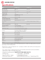
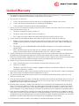
INSTALLATION &
OPERATION MANUAL
BCD605
DC Battery Charger
An ISO9001 and AS9100 Registered Company Battery Chargers • Inverters • Power Supplies • Voltage Converters
8128 River Way, Delta B.C. V4G 1K5 Canada T. 604.946.9981 F. 604.946.9983 TF. 800.668.3884 (US/CANADA)
www.analyticsystems.com
Copyright (2005-2014) Analytic Systems Ware (1993) Ltd.
IMPORTANT & SAFETY INSTRUCTIONS
SAVE THESE INSTRUCTIONS — This manual contains important safety and operating
instructions for the battery charger.
ALL BATTERY CHARGERS
1. CAUTION — To reduce risk of injury, charge only lead acid or sealed gel cell type
rechargeable batteries. Other types of batteries may burst causing personal injury and
damage.
2. Do not expose battery charger to rain or snow.
3. Use of an attachment not recommended or sold by the battery charger manufacturer may
result in a risk of fire, electric shock, or injury to persons.
4. Do not disassemble battery charger; take it to a qualified serviceman when service or
repair is required. Incorrect reassembly may result in a risk of electric shock or fire.
5. To reduce risk of electric shock, disconnect battery charger from batteries and AC supply
before attempting any maintenance or cleaning. Turning off controls will not reduce this
risk.
DC BATTERY CHARGERS
1. WARNING — RISK OF EXPLOSIVE GASES.
i.
WORKING IN VICINITY OF A LEAD-ACID BATTERY IS DANGEROUS. BATTERIES
GENERATE EXPLOSIVE GASES DURING NORMAL BATTERY OPERATION. FOR THIS
REASON, IT IS OF UTMOST IMPORTANCE THAT EACH TIME BEFORE SERVICING
EQUIPMENT IN THE VICINITY OF THE BATTERY, YOU READ THIS MANUAL AND FOLLOW THE INSTRUCTIONS EXACTLY.
ii. To reduce risk of battery explosion, follow these instructions and those published by
battery manufacturer and manufacturer of any equipment you intend to use in vicinity of battery. Review cautionary marking on these products and on engine.
2. PERSONAL PRECAUTIONS
i.
Someone should be within range of your voice or close enough to come to your aid
when you work near a lead-acid battery.
ii. Have plenty of fresh water and soap nearby in case battery acid contacts skin, clothing, or eyes.
iii. Wear complete eye protection and clothing protection. Avoid touching eyes while
working near battery.
iv. If battery acid contacts skin or clothing, wash immediately with soap and water.
If acid enters eye, immediately flood eye with running cold water for at least 10
minutes and get medical attention immediately.
3
v. NEVER smoke or allow a spark or flame in vicinity of battery or engine.
vi. Be extra cautious to reduce risk of dropping a metal tool onto battery. It might spark
or short-circuit battery or other electrical part that may cause explosion.
vii. Remove personal metal items such as rings, bracelets, necklaces, and watches when
working with a lead-acid battery. A lead-acid battery can produce a short-circuit current high enough to weld a ring or the like to metal, causing a severe burn.
viii. NEVER charge a frozen battery.
ix. If necessary to remove battery from service, always remove grounded terminal from
battery first. Make sure all accessories are off, so as not to cause an arc.
x. Be sure area around battery is well ventilated.
xi. Clean battery terminals. Be careful to keep corrosion from coming in contact with
eyes.
xii. Study all battery manufacturer’s specific precautions such as removing or not removing cell caps while charging and recommended rates of charge.
xiii. Add distilled water in each cell until battery acid reaches level specified by battery
manufacturer. This helps purge excessive gas from cells. Do not overfill. For a battery
without cell caps, carefully follow manufacturer’s recharging instructions.
3. BATTERY CHARGER LOCATION
i.
Never place battery charger directly above battery; gases from battery will corrode
and damage converter.
ii. Never allow battery acid to drip on battery charger when reading gravity or filling
battery.
4. DC CONNECTION PRECAUTIONS
Connect and disconnect all DC connections only after setting battery charger switch to
off position.
Analytic Systems does not recommend the use of the BCD605 Series Battery Chargers in life
support applications where failure or malfunction of this product can be reasonably expected
to cause failure of the life support device or to significantly affect its safety or effectiveness.
Analytic Systems does not recommend the use of any of its products in direct patient care.
Examples of devices considered to be life support devices are neonatal oxygen analyzers,
nerve stimulators (whether used for anesthesia, pain relief, or other purposes), autotransfusion devices, blood pumps, defibrillators, arrhythmia detectors and alarms, pacemakers,
hemodialysis systems, peritoneal dialysis systems, neonatal ventilator incubators, ventilators
for both adults and infants, anesthesia ventilators, and infusion pumps as well as any other
devices designated as “critical” by the U.S. FDA.
4
Introduction
This all new single board design incorporates state of the art switchmode technology for
unmatched efficiency and ultra-quiet operation. Multiple stages of filtering reduce radiated or
conducted noise to very low levels. Extra features include adjustable output voltage, audible
and visual indicators for low input voltage, low output voltage and over temperature. Safety
features include reverse input protection, over-temperature shutdown, current limiting, short
circuit protection with automatic recovery, input undervoltage shutdown, reverse battery
protection and output overvoltage crowbar. Optional features include a dry contact alarm relay
output, and remote panel monitoring with On/Off control.
We are confident that you will get many years of reliable service from this DC Battery Charger.
5
Specifications
Model
BCD605-12-12
BCD605-12-24
Input Volts (DC)
10.5 - 14
10.5 - 28
Input Amps (max)
50
Output Volts (DC)
13.6 ± 0.5 V
27.2 ± 0.5 V
Charging Amps
* 42
* 21
Output Crowbar
Output Volts x (1.3 ± 1%)
Input Fuses
AGC 30 x 2 Amp
Output Fuses
AGC 25 x 2 Amp
Low Input Voltage Alarm
10.5 VDC
Low Output Voltage Alarm
Output Voltage minus 2.5 VDC
Battey Banks
1
Stages
2
Battery Size (Amp Hours)*
168 - 252
Transient Response
< 1V for 15A Surge
Efficiency
> 85 % @ maximum output
Temperature Range
-25 to +40 deg° C @ maximum output
Isolation
Any Input or Output to Case 500VDC
Input to Output Common Negative
Length
9.1 in / 23.1 cm
Width
7.8 in / 19.8 cm
Height
4.3 in / 10.8 cm
Clearance
1 Inch (2.5 cm) all around
Material
Marine Grade Aluminum
Finish
Black Powder Epoxy
Fastenings
18-8 Stainless
Weight
6.0 lb / 2.7 kg.
2 (Only if the input voltage < 15 Vdc)
84 - 126
*The Actual charging rate depends upon the input/output voltage ratio. To obtain the charging capacity at any given
input voltage, use the following formula:
Charging Current = Input Volts/Output Volts x 40 For example, at 10.5VDC in and 13.6VDC out, the charging current
= 10.5/13.6 x 40 = 30.8 amps
* This is Analytic Systems’ suggested range. Please consult your battery manufacturer for their recommendations.
* Specifications subjects to change without notice.
Designed and manufactured by: ANALYTIC SYSTEMS WARE (1993) LTD.
8128 River Way
Delta, BC V4G 1K5 Canada
p. 604.946.9981 f. 604.946.9983 tf. 800.668.3884 US/Canada
www.analyticsystems.com
[email protected] Revised August 2014
6
Installation
MOUNTING
Mount the unit in a DRY location. Allow at least 1 inch of clearance for adequate cooling.
POWER CONNECTION
The unit is supplied with three foot power input leads. This should normally be adequate to
connect to a source of power. If you must extend the cable:
• Use the smallest extension length possible.
• Use no less than 10 gauge conductors.
• Splice and solder the joints.
• Protect the joints with heat shrink tubing.
Connect the wires as follows:
• Red to Positive
• Black to Negative
OUTPUT CONNECTIONS
Two positive output terminals and two negative output terminals are provided. Connect only
one wire to each terminal. A jumper externally connects the positive terminals of the BCD60512-24. This jumper may be removed and the BCD605-12-24 used as a dual bank charger if and
only if the input voltage is less than 15 volts.
Note that the current specifications are for input current. To obtain the maximum output
current capability at any given input voltage, use the following formula:
Output Current = Input Volts / Output Volts x 40
For example:
11 VDC in and 27 VDC out, the max output current = 11/27 x 40 = 16.3 Amps.
20 VDC in and 27 VDC out, the max output current = 20/27 x 40 = 29.6 Amps
Each output terminal can supply up to 25 Amps, therefore do not connect more than 25 amps
of load to either output terminal. If the load exceeds 25 Amps but not the continuous rated
output of the unit, do the following: The output terminals must be connected to the load in
parallel ensuring that the wiring used has sufficient capacity to handle the current.
PLEASE NOTE:
The BCD605-12-12 is a single bank charger ONLY and must be
hooked up as shown in the drawing to the right!
The BCD605-12-24 may be used as a dual bank charger if the
input voltage is less than 15 volts! If the input is greater than
15 volts the unit must be hooked up as shown in the drawing
to the right!
7
Operation
Turn the power switch on the front of the unit on to energize the outputs.
If you wish to adjust the output voltage, first attach a good digital voltmeter to the output
terminals to monitor the voltage. Next, remove the cover plate (secured by 2 screws) to
expose the output adjust potentiometer. Reach in with a very small flat blade screwdriver
to rotate the potentiometer. Clockwise increases the output voltage, and counter clockwise
decreases it. When you are done, replace the cover plate and securely tighten the screws.
Remove the voltmeter from the output terminals.
Troubleshooting
If the load exceeds the continuous rating for too long a period, the internal temperature sensor
will cause the unit to stop boosting the input voltage until the unit has cooled down. After the
unit has cooled down, normal operation will resume.
If the input voltage drops below the specified minimum input, the unit will sound the alarm.
If the output voltage drops below the specified minimum, the unit will sound the alarm.
If the current demanded by the devices connected to the unit exceed the maximum current
rating, the fuse will blow.
If the fuse blows with no load connected, check that the power leads are connected to the
battery with the correct polarity; if they are then the unit is damaged and must be returned for
repair.
Dry Contact Relay
To use your dry contact output fail relay you must connect a 9-pin D connector to the unit.
You must use pins one and six as is indicated on page 8 in the remote connector diagram.
The relay is factory preset to fail in the closed position when the low output LED and buzzer
come on. If you wish to have the relay fail in the open position when the low output LED and
buzzer come on, you must take the cover off the unit and move the jumper to the other position on J11. J11 is located next to the relay.
8
Remote Control Option
A remote control panel may be connected to the
converter using a 9-pin D-connector, which attaches
to the side of the battery charger. The remote control
panel and D connector are part of the remote control
option. The remote control panel allows the unit to
be operated remotely as well as duplicating all the
diagnostic indicators and audible alarm.
IMPORTANT: This remote is to be used only on Battery Chargers manufactured by
Analytic Systems.
REMOTE CONNECTOR
This connector is located on the side of the unit. Important: To prevent the possibility of High
Voltage Electrical Shock, do not power up the battery charger unless all wiring from the unit to
the remote is securely connected. Do not remove the dust cover from the DB-9 connector if the
remote is not being used.
9
Special Services & Options
Conformal Coating
INCLUDED ON ALL UNITS UNLESS REQUESTED NOT TO as of April 1, 2014
Option “c”
Ruggedization Package (EXTRA Conformal Coating and RTV Compound)
Option “v”
Marine / Industrial Pkg (EXTRA Conformal dipping and RTV Compound)
Option “MS”
Military Pkg
(incl. Wide Temp Components, Conformal Dipping and RTV Compound)
Option “w”
Wide Temperature Operation (-40 to +55 C, incl)
Option “SM”
High Voltage Protection on the DC Input Side
Option “d”
Paralleling Diodes
Option “FI”
Forklift Modifications
Option “F”
Open Frame - No chassis just heat sink bars (not for all products)
Special Input
Special Output
There is no charge for nominal output voltages (ie. 12.0, 24.0, 48.0), but this
must be noted at the time of order (Contact Factory for details)
Water tight options
IP66, IPS67, IPS68
10
Limited Warranty
1. The equipment manufactured by Analytic Systems Ware (1993) Ltd. (the “Warrantor”) is warranted to be free
from defects in workmanship and materials under normal use and service.
2. This warranty is in effect for:
a. 3 Years from date of purchase by the end user for standard products offered in our catalog.
b. 2 Years from date of manufacture for non-standard or OEM products
c.
1 Year from date of manufacture for encapsulated products.
3. Analytic Systems will determine eligibility for warranty from the date of purchase shown on the warranty card
when returned within 30 days, or
a. The date of shipment by Analytic Systems, or
b. The date of manufacture coded in the serial number, or
c.
From a copy of the original purchase receipt showing the date of purchase by the user.
4. In case any part of the equipment proves to be defective, the Purchaser should do the following:
a. Prepare a written statement of the nature of the defect to the best of the Purchasers knowledge, and
include the date of purchase, the place of purchase, and the Purchasers name, address and telephone
number.
b. Call Analytic Systems at 800-668-3884 or 604-946-9981 and request a return material authorization
number (RMA).
c.
Return the defective part or unit along with the statement at the Purchasers expense to the Warrantor;
Analytic Systems Ware (1993) Ltd., 8128 River Way, Delta, B.C., V4G 1K5, Canada.
5. If upon the Warrantor’s examination the defect proves to be the result of defective material or workmanship,
the equipment will be repaired or replaced at the Warrantor’s option without charge, and returned to the
Purchaser at the Warrantor’s expense by the most economical means. Requests for a different method of return
or special handling will incur additional charges and are the responsibility of the Purchaser.
6. Analytic Systems reserves the right to void the warranty if:
a. Labels, identification marks or serial numbers are removed or altered in any way.
b. Our invoice is unpaid.
c.
The defect is the result of misuse, neglect, improper installation, environmental conditions, non-authorized repair, alteration or accident.
7. No refund of the purchase price will be granted to the Purchaser, unless the Warrantor is unable to remedy the
defect after having a reasonable number of opportunities to do so.
8. Only the Warrantor shall perform warranty service. Any attempt to remedy the defect by anyone else shall
render this warranty void.
9. There shall be no warranty for defects or damages caused by faulty installation or hook-up, abuse or misuse of
the equipment including exposure to excessive heat, salt or fresh water spray, or water immersion except for
equipment specifically stated to be waterproof.
10.No other express warranty is hereby given and there are no warranties that extend beyond those described
herein. This warranty is expressly in lieu of any other expressed or implied warranties, including any implied
warranty of merchantability, fitness for the ordinary purposes for which such goods are used, or fitness for a
particular purpose, or any other obligations on the part of the Warrantor or its employees and representatives.
11.There shall be no responsibility or liability whatsoever on the part of the Warrantor or its employees and representatives for injury to any person or persons, or damage to property, or loss of income or profit, or any other
consequential or resulting damage which may be claimed to have been incurred through the use or sale of the
equipment, including any possible failure of malfunction of the equipment, or part thereof.
12.The Warrantor assumes no liability for incidental or consequential damages of any kind
11
An ISO9001 and AS9100 Registered Company Battery Chargers • Inverters • Power Supplies • Voltage Converters
8128 River Way, Delta B.C. V4G 1K5 Canada T. 604.946.9981 F. 604.946.9983 TF. 800.668.3884 (US/CANADA)
www.analyticsystems.com