1
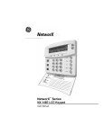
NetworX™ Series
NX-148E LCD Keypad
Installation and Setup
Includes models NX-148E, NX-148E-CF, and NX-148E-CF-W
© 2005 GE Security
All rights reserved.
These instructions do not purport to cover all details or variations in equipment nor to provide every
possible contingency to be met during installation, operation, and maintenance. If further information is
desired or if particular problems arise that are not covered sufficiently for the purchaser’s purpose, the
matter should be referred to GE Security, USA.
This document contains proprietary information of GE Security, USA and is furnished to its customer
solely to assist that customer in the installation, testing, operations, and/or maintenance of the equipment
described. This document shall not be reproduced in whole or in part nor shall its contents be disclosed to
any third party without the written approval of GE Security.
Please refer to the current GE Security product catalog for detailed warranty information.
Main
Outside the US
Main Fax
800-727-2339
903-845-6941
903-845-6811
Technical Support
888-437-3287
Sales & Literature
800-547-2556
Web: www.ge-security.com
SAFETY SYMBOL LEGEND
Indicates a procedure, practice, condition, or statement that, if not strictly observed,
could result in personal injury.
Warning
* This symbol indicates electrical warnings and cautions.
Indicates a procedure, practice, condition, or statement that, if not strictly observed,
could result in damage to or destruction of equipment or property.
Caution
** This symbol indicates general warnings and cautions.
Indicates an essential or important procedure, instruction, condition, or statement.
Note
Tip
Indicates a user tip. Provides helpful information that is not normally defined in
regular use, but from an experienced user.
Indicates a key or button should be pressed to enter data.
Enter
2
LCD KEYPAD
Table of Contents
1.
ENTERING THE PROGRAM MODE....................................................................................................... 4
2.
SELECTING THE MODULE TO PROGRAM ........................................................................................ 4
3.
PROGRAMMING A LOCATION .............................................................................................................. 4
3A. NUMERICAL DATA......................................................................................................................... 4
3B. BINARY DATA ................................................................................................................................. 5
3C. CHARACTER DATA ........................................................................................................................ 5
4.
LOADING FACTORY DEFAULTS........................................................................................................... 7
5.
ENROLLING................................................................................................................................................. 7
6.
PROGRAMMING THE KEYPADS ........................................................................................................... 8
6A. USING THE FUNCTION MENU ..................................................................................................... 8
6B. ADJUSTING THE VIEW & BRIGHTNESS OF THE LCD ............................................................ 9
6C. CUSTOM MESSAGES...................................................................................................................... 9
6D. CUSTOM MESSAGES IN LANGUAGE 2 .................................................................................... 10
6E. SET KEYPAD OPTIONS ................................................................................................................ 10
6F. SET KEYPAD NUMBER AND PARTITION ................................................................................ 11
7.
KEYPAD FUNCTIONS.............................................................................................................................. 12
7A. READING THE EVENT LOG ........................................................................................................ 12
7B. SET ELAPSED TIME IN MINUTES SINCE LAST AUTOTEST................................................. 13
7C. SET SYSTEM TIME AND DATE .................................................................................................. 14
7D. ADJUST KEYPAD TONE............................................................................................................... 14
7E. VIEW ZONE STATUS .................................................................................................................... 14
7F. VIEW ALARM MEMORY.............................................................................................................. 15
7G. TEST FUNCTION............................................................................................................................ 15
7H. DISPLAY TEST FUNCTION.......................................................................................................... 15
7I. LIGHT CONTROL FOR X-10 DEVICES....................................................................................... 15
7J. HOUSE CODES FOR X-10 DEVICES ........................................................................................... 16
7K. CHANGE LANGUAGES ................................................................................................................ 16
7L. CHANGING USER CODES............................................................................................................ 16
7M. ASSIGNING AUTHORITY LEVEL............................................................................................... 17
7N. RESET FUNCTION ......................................................................................................................... 18
7O. OTHER FUNCTIONS...................................................................................................................... 18
8.
PARTITIONED SYSTEMS OPERATION.............................................................................................. 19
8A. MASTER MODE ............................................................................................................................. 19
8B. “TEMPORARY” MASTER MODE ................................................................................................ 19
8C. LIGHTS IN PARTITIONING MASTER MODE............................................................................ 19
8D. DISPLAYS IN THE PARTITIONING MASTER MODE .............................................................. 20
9.
SERVICE DISPLAY................................................................................................................................... 21
10.
MAXIMUM WIRE RUN............................................................................................................................ 23
11.
SPECIFICATIONS ..................................................................................................................................... 24
LCD KEYPAD
3
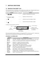
1. ENTERING THE PROGRAM MODE
ACTION
RESULT
[Go
To
Factory Default is
Enters the Program Mode.
Prompts for the programming code.
Program
Code
]
If the "Go To Program Code" is valid, the LCD
screen will prompt for the device address to program.
You are now in the Program Mode and ready to
select the module.
2. SELECTING THE MODULE TO PROGRAM
Tip: All modules connected to the NX control panel are programmed through the keypad. So the module
you are programming should be the first entry.
#
Programs the NX Control Panel
is the module number of the control and # is
the entry key. Other module entry numbers can
be found in their corresponding manuals.
3. PROGRAMMING A LOCATION
Once the number of the module to be programmed has been entered, the LCD screen will prompt you for
a location number. Any location can be accessed by directly entering the desired programming location
followed by the pound [#] key. If the location entered is a valid location, the top line of the LCD screen will
display the location number on the left and the segment number on the right. The bottom line of the
display will show the current data. This data will be displayed and entered according to the type of data
used (numerical, binary, or character data). Follow the instructions below for each type of data.
3a. NUMERICAL DATA
The top line of the display will show the current location number on the left and the segment number on
the right. The data will be displayed on the bottom line. The hex equivalent will be shown in parenthesis.
To change the data in the current location, enter the number followed by . The data will be entered and
the segment will be incremented by 1. The data for this segment will now be displayed. Continue this
process until the last segment is programmed. When the last segment is reached, the keypad will prompt
you for the next location. If you wish to exit this location before the last segment is reached, press #. This
keypress will not save the changes made to current segment, but will exit the location.
Shortcut keys:
4
Previous location.
Same location.
Next sequential location.
LCD KEYPAD
3b. BINARY DATA
The top line of the display will show the current location number on the left and the segment number on
the right. The data will be displayed on the bottom line with the numbers 1-8 in the first 8 characters. If
the number appears, this binary switch is on. If a minus sign (-) appears where the number should be, this
switch is off. Toggle numbers on or off using the corresponding number digit (1 to toggle 1; 8 to toggle 8).
When the numbers are in the desired state, enter . The data will be entered and the segment will be
incremented by 1. The data for this segment will now be displayed. Continue this process until the last
segment is programmed. When the last segment is reached, the keypad will prompt for the next location.
If you wish to exit this location before the last segment is reached, press #. This keypress will not save the
changes made to current segment, but will exit the location. “Shortcut Keys” shown in Numerical Data can
also be used for Binary Data.
3c. CHARACTER DATA
Character Data is used to enter LCD text when programming. (Refer to feature on page 9 for
custom messages.) Custom zone descriptions and messages are stored character or ASCII data type.
This information is programmed using the bottom line of the display as a text editor. Once a character
location has been entered, the current data will be displayed on the bottom line. As is always the case,
the top line will display the current location and segment number. The five (5) function keys, as well as the
up and down arrow to the right of the display, are now used to edit the message prior to saving it back to
the location storage. An underscore (_) in the display indicates the current cursor location.
Shortcut keys:
CANCEL
Saves character or word; moves cursor to right
Moves cursor to left.
or Scrolls through available characters. (SeeTip)
(In Library Mode) Scrolls through available
words.
STAY
CHIME
EXIT
BYPASS
Inserts blank space.
Deletes characters.
Accesses the Library (page 6)
Makes the character “flash”.
(In Library Mode) Makes the entire word “flash”.
#
Exits the edit mode.
Tip: An alternate method is to enter the 2-digit number found in Table 3-1 or Table 3-3 that
corresponds to the desired character. To accept this character, press . The character will remain and
the cursor will advance one space to the right.
LCD KEYPAD
5
Table 3-1 ENGLISH CHARACTERS
No.
No.
00
01
12
13
02
03
04
05
06
07
08
09
10
11
A
B
C
D
E
F
G
H
I
J
K
14
15
16
17
18
19
20
21
22
23
No.
L
M
N
O
P
Q
R
S
T
U
V
W
24
25
26
27
28
29
30
31
32
33
34
35
No.
36
37
X
Y
Z
0
1
2
3
4
5
6
7
8
38
39
40
41
42
43
44
45
46
47
No.
9
a
b
c
d
e
f
g
h
I
j
k
48
49
50
51
52
53
54
55
56
57
58
59
No.
l
m
n
o
p
q
r
s
t
u
v
w
60
61
62
63
64
65
66
67
68
69
70
71
No.
72
73
x
y
z
!
"
#
$
%
&
'
(
)
74
75
76
77
78
79
80
81
82
83
No.
r
+
,
.
/
:
;
<
=
>
?
84
85
86
87
88
89
90
91
92
93
94
95
@
[
ù
]
^
_
`
{
|
}
º
»
Table 3-2 ENGLISH LIBRARY
ALARM
DETECTOR
GARAGE
LIBRARY
PIR
SMOKE
VAULT
AREA
DINING
GLASSBREAK
LIGHT
PORCH
SOUND
WAREHOUSE
AUDIO
DOOR
GUEST
LIVING
ROOM
SOUTH
WEST
BACK
DOWN
HALL
MASTER
RUMPUS
STAIRS
WINDOW
BATHROOM
DURESS
HEAT
MICROWAVE
SAFE
STORAGE
WING
BEAM
EAST
HOLDUP
MOTION
SENSOR
STUDY
WIRELESS
BEDROOM
EMERGENCY
HOUSE
NORTH
SHOCK
TAMPER
YARD
BUTTON
EXIT
INFRARED
NURSERY
SHOP
TELEVISION
ZONE
CEILING
EXTERIOR
INSTANT
OFFICE
SIDE
TROUBLE
CLOSET
FIRE
INTERIOR
PANIC
SKYLIGHT
TV
DELAY
FRONT
JUNK
PANTRY
SLIDING
UP
DEN
GAME
KITCHEN
PHONE
SMALL
UTILITY
Table 3-3 AMERICAN SPANISH CHARACTERS
No.
No.
00
01
12
13
02
03
04
05
06
07
08
09
10
11
6
A
B
C
D
E
F
G
H
I
J
K
14
15
16
17
18
19
20
21
22
23
No.
L
M
N
Ñ
O
P
Q
R
S
T
U
V
24
25
26
27
28
29
30
31
32
33
34
35
No.
W
X
Y
Z
0
1
2
3
4
5
6
7
36
37
38
39
40
41
42
43
44
45
46
47
No.
8
9
a
á
b
c
d
e
é
f
g
h
48
49
50
51
52
53
54
55
56
57
58
59
No.
i
í
j
k
l
m
n
ñ
o
ó
p
q
60
61
62
63
64
65
66
67
68
69
70
71
No.
r
s
t
u
ü
ú
v
w
x
y
z
!
72
73
74
75
76
77
78
79
80
81
82
83
No.
"
#
&
'
(
)
r
+
,
.
/
84
85
86
87
88
89
90
91
92
93
94
95
:
;
<
=
>
@
[
ù
]
^
_
`
LCD KEYPAD
Table 3-4 AMERICAN SPANISH LIBRARY
ABAJO
CONTACTO
EXTERIOR
JARDIN
PRINCIPAL
SOTANO
ALARMA
CRISTAL
FACHADA
LABORATORIO
PUERTA
TALLER
ALMACEN
DESPACHO
FUEGO
LATERAL
RECEPCION
TECHO
ARRIBA
DETECTOR
GARAJE
LAVABO
RECIBIDOR
TERRAZA
AVERIA
DISPARO
GERENCIA
MAGNETICO
SABOTAJE
TIENDA
AZOTEA
DOBLE TECHNOLOGIA
GOLPE
OFICINA
SALA
TRASERO
BARRERA
DORMITORIO
HABITACION
PANICO
SALIDA
VALLA
CAJA FUERTE
EMERGENCIA
HUMO
PARED
SALON
VENTANA
CLARABOYA
ENTRADA
INFORMATICA
PASILLO
SENSOR
VESTIBULO
COCINA
ESTACIONAMIENTO
INFRARROJO
PERSIANA
SILENCIOSA
ZONA
COMEDOR
ESTUDIO
INTERIOR
PLANTA
SIRENA
4. LOADING FACTORY DEFAULTS
ACTION
RESULT
Follow procedures on page 4 (Sections 1 and 2) and enter the Program Mode for the module to default.
#
Keypad will beep 3 times (loading is in progress).
The loading takes about 6 seconds.
To load the factory defaults for the LCD keypad,
enter the Program Mode from a different keypad
(does not have to be LCD keypad), and follow the
same procedures.
The two-line Custom and two-line Shutdown Messages will not be defaulted.
5. ENROLLING
For supervision purposes, the NetworX control panel has the ability to automatically find and store in its
memory the presence of all keypads, zone expanders, wireless receivers, and any other module
connected to the data terminal. This allows these modules to be supervised by the control panel. NOTE:
All modules should be connected and set to unique addresses prior to enrolling modules. To enroll the
modules, enter the Program Mode of the NetworX control panel. When the Program Mode is exited, the
control will enroll the devices. The enrolling process takes about 12 seconds, during which time the
"Service Required" will be displayed. Once a module is enrolled, if it is not detected by the control, the
"Service Required@ will be displayed.
LCD KEYPAD
7
6. PROGRAMMING THE KEYPADS
This section describes how to program the address and partition of each keypad, as well as the available
options. The address of the keypad is important because this is how the panel supervises the keypads.
FACTORY DEFAULTS:
Master Code: when using a 4-digit code, or for a 6-digit code
Go To Program code: when using a 4-digit code, or for a 6-digit code
6a. USING THE FUNCTION MENU
ACTION
RESULT
Accesses the Function menu.
The display will begin scrolling though available
functions. (Table 6-1 shown below.)
Press the number(s) listed for that function.
Displays the next menu item.
#
Exits the Function Menu.
Tip: If you know the function numbers
simply press [ function number].
(example only)
These are samples of the displays that will scroll automatically
in the Function Menu.
Table 6-1 provides a list of the Function Menu items, as well as
page references for further instructions.
Select an Option
Press for help
Select an Option
= Zone Review
Table 6-1 FUNCTION MENU
FUNCTION
RESULT
Adjust keypad tone
PG
14
FUNCTION
Temp Master Mode
View zone status
19
14
Service menu
View alarm memory
Test function
Display test function
21
15
15
15
Light control for X-10
House codes for X-10
15
16
Change languages
8
RESULT
Reset function
PG
18
Log review
Adjust view / brightness of LCD
12
9
9
10
11
13
Programming custom messages
Set keypad options
Set keypad number and partition
Set elapsed time in minutes since
last autotest
Set system time and date
Call back for download
14
18
16
Seize phone line for download
18
Changing user codes
16
CHIME
Walk Test
18
Assigning user authority
17
EXIT
Silent Exit
LCD KEYPAD
6b. ADJUSTING THE VIEW & BRIGHTNESS OF THE LCD
ACTION
RESULT
Prompts to “Please Enter Your Code".
[master code]
Prompts to raise or lower the View angle.
or Using the scroll keys to the right of the LCD, you
can raise or lower the viewing angle of the text.
Advances to the Brightness option.
or Use the scroll keys again to adjust to desired
brightness.
Exits this mode.
Prompts to brighten or dim the LCD lighting.
6c. CUSTOM MESSAGES
IMPORTANT
1)
2)
3)
4)
NOTES
When using standard NX-148 keypad(s) and NX-148E keypad(s) in the same system, it is
necessary to use a NON-“E” keypad to program the custom messages. The NON-“E” keypads
can be identified by the fact that they do not display a menu when is pressed.
The messages (custom, zone, and shutdown) are transferred to other LCD keypads after this mode
is exited. All keypads must be addressed and enrolled for this to happen.
Use the function to set the keypad numbers prior to programming custom messages.
If a keypad is added after messages are programmed, you should either program ALL messages in
it, or enter custom message programming on an existing keypad and make changes. This is to
prevent accidentally overwriting existing messages. Refer to option to prevent overwriting
the custom message only.
ACTION
RESULT
[program code]
LCD KEYPAD
Prompts to “Please Enter Your Code".
The LCD will now prompt you to enter message
number followed by #.
Zones 1 through 192 custom messages are
message numbers 1-192 respectively.
Message 193 - Custom message top line.
Message 194 - Custom message bottom line.
Message 195 - Shutdown message top line.
Message 196 - Shutdown message bottom line.
9
[message number] #
The LCD will display the zone number on the top
line and the description will be on the bottom line.
Use the instructions on page 5 for editing
character data.
Any changes will automatically be copied to all
other LCD keypads in the system.
EXIT
If you desire an LCD keypad to have a different
custom message, you must enable Custom
Message Lock under the function (pg 10)
6d. CUSTOM MESSAGES IN LANGUAGE 2
Tip: Exit mode prior to changing languages.
ACTION
Proceed with steps for usual RESULT
Keypad is now toggled to the second language.
programming.
6e. SET KEYPAD OPTIONS
ACTION
RESULT
[program code]
Prompts to “Please Enter Your Code".
The LCD will now prompt you through the options
listed on the following chart.
The current state of the option will be shown in
the lower right corner of the display.
Advances to the next option without making
changes.
Otherwise, follow the instructions on the bottom
line of the LCD display to select the desired
option. This will also advance to the next option.
10
LCD KEYPAD
OPT
1
2
3
4
5
6
7
8
9
10
11
12
KEYPAD FEATURES
NOT USED
SILENT KEYPAD?
Enable Silent Keypad Option. If enabled, only the entry/exit and
sounder chime are silenced.
DING DONG CHIME?
Enable Ding Dong Sound for Chime. If off, chime will be a single
tone. (Refer to NX control panel installation manual, location 40)
5 SEC. SILENCE?
Enable Keypress Silence Option. Silences the pulsing keypad
sounder for 5 seconds when a key is pressed.
ARMED ZONE INFO?
Enable Armed Zone Information. If on, the LCD keypad will display
faulted or bypassed zone information when the system is armed.
BEEP ON PANICS?
Enable Panic, Fire, and Medical Beeptone. Will sound a short beep
to verify that the keypress was accepted.
DISABLE SERVICE?
Suppresses the "Service" Message. This will not allow the "Service
Required" message to be displayed for any reason. If there is a
system trouble, r will still show the "Service Required" menu.
MASTER KEYPAD?
Enable Multi-partition Mode
CUSTOM MESSAGE?
Enable Custom Message Display
CLOCK?
Enable Clock Display
CUSTOM MSG. LOCK? Enable Custom Message Lock. Prevents over-writing the custom
message during keypad copy.
SELECT AN OPTION: Programs special characteristics.
1=Display “Press r For Help”
2=Disable LED Extinguish on this keypad
3=On if PIN should be hidden when programming
4=On suppresses beeps when an RF transmission is lost
5-8=RESERVED (Do not program!)
6f. SET KEYPAD NUMBER AND PARTITION
ACTION
RESULT
Prompts to “Please Enter Your Code".
[program code]
Prompts for the keypad number.
The current keypad number will be displayed
in the lower right hand corner.
[keypad number] [partition number] LCD KEYPAD
Prompts for the partition number.
The current partition will be displayed in the
lower right hand corner.
Automatically exits this mode.
11
7. KEYPAD FUNCTIONS
7a. READING THE EVENT LOG
The control panel has an event log that can be retrieved using a master code. This log contains a listing
of the last 185 events along with date, time, and partition where the event occurred.
ACTION
RESULT
Prompts to “Please Enter Your Code".
[master code]
Shows the most recent event.
Views the events from newest to oldest.
Views the events from oldest to newest.
The display contains the following information.
User or Zone ID
Event
Open
Date
(Month/Day)
9/25
75
17:57
P3
Time shown in
24-hour format
Partition number
indicates an event
not reported
th
This screen shows an opening of Partition 3 on September 25 at 5:27 p.m. by user 75. The shows
that this event is not programmed to be reported to the central monitoring station.
POSSIBLE LOG MESSAGES
DISPLAY
TXlobat
ZN Lost
Duress
Man Fire
Aux 2
Panic
KP Tamper
BoxTamp
AC Fail
OverCur
Srn Tamp
Tel Flt
Exp Trb
Log Full
12
DESCRIPTION
Transmitter Low Battery - The transmitter has a low battery.
Zone Lost - A wireless or multiplexed zone device is not reporting to the control.
Duress - The control has been armed or disarmed with a Duress code.
Manual Fire - Keypad “Fire” has been activated.
Auxiliary 2 - Keypad “Medical” has been activated.
Panic - Keypad “Panic” has been activated.
Keypad Tamper - The keypad tamper has been activated.
Box Tamper - The box tamper circuit has been activated.
AC Fail - AC failure has been detected.
Over Current - A short circuit of a power supply has occurred.
Siren Tamper - A siren or speaker tamper has been detected.
Telephone Fault - A telephone fault or tamper has been detected.
Expansion Trouble - An expansion device or keypad is not reporting to the control.
Log Full - The event log is full.
LCD KEYPAD
DISPLAY
Open
Close
Exit Err
Rec Close
Autotest
Start Prog
End Prog
Start Dnld
End Dnld
Cancel
Gnd Flt
Man Test
Re-exit
Output Trip
Data Lost
Walk-test
End Test
Cross-Trip
Expansion
Event
Partial Arm
Listen In
Service Start
Service End
Code Entry
First Open
Last Close
Sprnklr
Clock Set
RF Jammed
CleanMe
DESCRIPTION
Open - Reports user number, date, time and partition of opening.
Close - Reports user number, date, time and partition of closing.
Exit Error - Entry/Exit zone was faulted at the instant the exit delay expired.
Recent Close - An alarm occurred within 5 minutes after the control was armed.
Auto Test - Sending a communicator test at a specified interval.
Start Programming - Local programming is started.
End Programming - Local programming is ended.
Start Download - Download session is started.
End Download - Download session is ended.
Cancel - System is disarmed; Cancel was initiated within 5 minutes of an alarm.
Ground Fault - A short to ground has been detected.
Manual Test - Bell and/or communicator test while system is in disarmed condition.
Re-Exit - The exit delay has been re-started without disarming the system.
Output Trip - A trip has occurred on an expander auxiliary output.
Data Lost - Communication of a signal has failed (log only event).
Walk-Test - A zone “Walk-Test” mode has been activated.
End Test - Test has been ended.
Cross Trip - The first zone of a cross zone has been tripped (log only event).
Expansion Event - An expansion module has created an undefined event.
Partial Arm - Reports a closing in the stay mode.
Listen In - A listen in function has been activated.
Service Start - Technician is on site.
Service End - Technician is off site.
Code Entry - A code has been entered.
First Open - Reports when the first partition is disarmed.
Last Close - Reports when the last partition is armed.
Sprinkler - Instant sprinkler supervisory report
Clock Set - Clock has been reset.
RF Jammed - A wireless expansion module is jammed
CleanMe - A smoke detector requires cleaning.
7b. SET ELAPSED TIME IN MINUTES SINCE LAST AUTOTEST
ACTION
RESULT
Prompts for a code.
[program code]
Displays the elapsed time screen.
[100's digit] [10's digit] [1's digit]
#
Saves and exits.
(example only)
LCD KEYPAD
13
7c. SET SYSTEM TIME AND DATE
ACTION
RESULT
[master code]
Displays date and time with the current hour
flashing.
or Scroll to select the proper hour.
Advances to the selection for the minutes.
Prompts to “Please Enter Your Code".
Repeat the last two steps until the entire time and date is set.
7d. ADJUST KEYPAD TONE
ACTION
RESULT
Prompts to use the scroll keys (right of the display)
to raise or lower the tone.
to raise the tone
to lower the tone
The keypad will emit a continuous tone to allow
you to hear the current selection.
#
Saves the tone and exits the mode.
7e. VIEW ZONE STATUS
ACTION
RESULT
Displays the zone status.
or Displays the list of ALL zones in sequential order
by zone number.
#
Exits the mode.
14
LCD KEYPAD
7f. VIEW ALARM MEMORY
ACTION
RESULT
Displays the zone descriptions.
or Displays the alarm memory list in sequential order
by zone number.
#
Exits the mode.
7g. TEST FUNCTION
ACTION
RESULT
Test will be performed as programmed.
If the siren test is performed, enter a user code
to silence the siren.
7h. DISPLAY TEST FUNCTION
ACTION
RESULT
All display pixels and LED indicators will flash.
Press any key to end test.
7i. LIGHT CONTROL FOR X-10 DEVICES
When used in conjunction with an X-10 output device such as the NetworX NX-507E, NX-508E, NX-534E
or NX-540E, this menu allows the user to control up to ten X-10 devices from each keypad.
ACTION
RESULT
Prompts to “Select Light Number 0-9”.
[device number]
Displays the light number on the left.
to turn ON
to turn OFF
#
LCD KEYPAD
Prompts to turn the light “On” or “Off” on the right.
Prompts to “Select Light Number 0-9”.
Repeat steps 2 and 3 until all devices have been
programmed.
Exits the function.
15
7j. HOUSE CODES FOR X-10 DEVICES
When used in conjunction with an X-10 output device such as the NetworX NX-507E, NX-508E, NX-534E
or NX-540E, this menu allows the installer to program the specific X-10 unit and house codes for the ten
X-10 devices for this keypad.
ACTION
RESULT
Prompts to “Please Enter Your Code".
[program code]
Displays Light number and Unit Code.
[X-10 unit code] Prompts for the House Code of the device.
[X-10 house code] Prompts for the House Code of the device.
Repeat steps 3 and 4 until all devices have been
programmed.
#
Exits the function.
7k. CHANGE LANGUAGES
ACTION
RESULT
Keypad toggles to the second language.
Keypad reverts to the first language.
7l. CHANGING USER CODES
Tip: For partitioned systems, someone changing the code of another person must have access to all or
more partitions than the user being changed.
ACTION
RESULT
Prompts “Please Enter Your Code".
[master code]
Prompts for a user number.
[user code]
Prompts for a new code.
2-digit ID if NX-4, NX-4V2, NX-6,
NX-6V2, NX-8, NX-8V2, NX-8-CF
3-digit ID if NX-8E, NX-8E-CF (use
leading zeros!! (i.e. for user 7)
16
LCD KEYPAD
[new user code]
Prompts for a user number. Repeat steps 3 and 4
if another user code needs to be programmed.
Keypad will beep 3 times if code is rejected.
#
Exits and saves data.
while display is prompting
for a user number.
7m. ASSIGNING AUTHORITY LEVEL
You must have authority to the partition you wish to add or remove from another person’s authority.
ACTION
RESULT
Prompts “Please Enter Your Code".
[master code]
Prompts for a user number.
[user code]
Prompts through the following list of attributes.
2-digit ID if NX-4, NX-4V2, NX-6,
NX-6V2, NX-8, NX-8V2, NX-8-CF
3-digit ID if NX-8E, NX-8E-CF (use
leading zeros!! (i.e. for user 7)
Outputs used?
If NO…
Master code?
Sched arm only?
Arm only?
Reserved
If YES…
Output 4 enable?
Output 3 enable?
Output 2 enable?
Output 1 enable?
Open / Close Rprt?
Bypass enable?
Arm / Disarm?
[partition number]
Saves data. Prompts for next user code. Return to
step 3 to program another user code.
#
Exits this mode.
Default allows access to ALL partitions.
The first keypress will remove access to the
partition. To reestablish access, press the partition
number again.
NOTE TO INSTALLER: Any master arm/disarm code can add or change a user code if the master
code has access to the same partitions as the code being added/changed. Consequently, when
programming the user codes for a partitioned system, leave at least one code access to all
partitions or you will not be able to add new users (can be "go to program code" if enabled in
location 43 of the control panel). If you desire the end user to be able to add new codes, you must
remove the partition authority from all blank codes.
LCD KEYPAD
17
7n. RESET FUNCTION
The system must be disarmed to perform this function.
ACTION
RESULT
The smoke detectors, zone troubles, and zone
tampers have now been reset.
If the keypad begins beeping, the reset did not execute properly. Enter your code to silence the keypad.
Wait a few minutes and repeat step 2 to attempt another reset.
7o. OTHER FUNCTIONS
(while system is disarmed) Causes the control to do a callback for a download.
A valid user code may be required if feature is enabled in location 41 of the
control panel. (Refer to the NX Control Panel Installation Manual)
(while system is disarmed) Causes the control to seize the phone line for a download.
A valid user code may be required if feature is enabled in location 41 of the
control panel. (Refer to the NX Control Panel Installation Manual)
CHIME
18
(must be enabled in the control panel) Entering r CHIME followed by a user code
will allow a walk-through zone test where all zones become silent and local (nonreporting). Each time a zone is faulted, the number of the faulted zone(s) will be
displayed on the keypad and the chime will sound. It will also be entered into alarm
memory and the internal log. To exit at any time during this mode, enter a user code.
Otherwise, the AWalk-Test Mode@ will automatically exit after 15 minutes.
LCD KEYPAD
8. PARTITIONED SYSTEMS OPERATION
8a. MASTER MODE
The LCD keypad can be programmed to operate all the system partitions simultaneously. To set the
multi-partition mode, use the function as described on page 10, and answer "YES" to the
question "Master keypad?"
8b. “TEMPORARY” MASTER MODE
Press [user code] to temporarily access the Master Mode.
The keypad will revert back to its
assigned partition 60 seconds after a key press or 10 seconds without a key press. Press # to exit.
8c. LIGHTS IN PARTITIONING MASTER MODE
#
ARMED will illuminate if ALL partitions are armed.
#
READY will illuminate if ALL partitions are "Ready". The ready light will flash if all areas are
Ready or Force armable.
#
FIRE will illuminate if ANY one area has a Fire condition. The fire light will flash if ANY area
has a Fire Trouble condition.
#
POWER will illuminate if the primary power is connected to the NX8-E control panel. It will
flash if the system has a low standby battery condition.
#
STAY will illuminate if ANY area has the stay light on.
#
CHIME will illuminate if ANY partition is in the "Chime" mode.
#
EXIT will illuminate if ANY area is timing an exit delay. It will flash if ANY area is in the last 10
seconds of an exit delay.
#
BYPASS will illuminate if ANY area has a zone bypassed.
#
CANCEL will flash during an abort delay time. If a code is entered followed CANCEL while
this light is flashing, all abortable reports will stop the communication process to the central
station. If a code is entered followed by CANCEL during or after an alarm report, the cancel
light will illuminate and remain constant until the central station has received the cancel
report.
#
SOUNDER will sound if ANY area has the sounder on. This includes Entry delay, Exit delay,
Chime, and Alarm.
LCD KEYPAD
19
8d. DISPLAYS IN THE PARTITIONING MASTER MODE
ARMED AND READY STATUS
The LCD screen will display the Armed and Ready status of ALL eight (8) partitions if any or all of the
areas is armed or not ready. Refer to the following examples:
All 8 areas are Ready, and areas 3 and 5 are disarmed.
Ready
Armed
12345678
12-4-678
Flashing number on the ready line = area is ready to be Force Armed.
Flashing number on the armed line = area is armed Instant.
System Ready
Type code to arm
ALL areas are disarmed and ready to arm.
ARMING AND DISARMING MULTIPLE PARTITIONS
12-45-78
Disarm º
--3
Arm
67-
º
To arm/disarm multiple partitions, enter a code that has arm/disarm
authority for ALL of the partitions to be armed/disarmed. A display
similar to the one on the left will appear on the LCD screen.
TOP LINE OF DISPLAY = disarmed areas to which this code has access
BOTTOM LINE OF DISPLAY = areas that are armed
Table 8-1 List of Possible Conditions
LCD DISPLAY
If area number is ….
Blank
Blank
Dash (-)
Dash (-)
Flashing
Dash (-)
Dash (-)
Flashing
Area #
Dash (-)
Dash (-)
Area #
20
CONDITION
Area Not Used or Authorized
Area Not Ready
Area Ready to Force Arm
Area Armed Instant
Area Disarmed & Ready to Arm
Area is Armed
To disarm all of the areas, press •.
To arm all of the areas, press –.
To toggle a single area between the armed and disarmed conditions, press [Area number]. For
example, if Area 4 is armed, will disarm Area 4. If Area 4 is disarmed, will arm it.
To control the individual areas, refer to the following section “Operating Individual Areas in the MultiPartition Mode”.
LCD KEYPAD
Operating Individual Areas in the Multi-Partition Mode
Enter a code that is a valid arm/disarm code for the area you wish to operate.
12-45-78
Disarm
--3-56--
Arm
º
º
Only the areas authorized by this user code will appear.
To toggle between the armed and disarmed states on an individual area, press [Area Number].
To operate an individual area, enter the number of the partition you wish to operate. The LCD keypad
will now operate as a single area keypad. All keys and functions entered will affect this individual
partition only. The lights and LCD display represent the status of that partition only. The word
"System" will be replaced with the word "Area #". The following is an example of this feature.
Press # to exit.
Area 5 Ready
Type code to arm
Area 5 is selected and Area 5 is ready to arm.
Press # # to exit the individual partition mode.
Silencing Alarms in the Multi-Partition Mode
If the keypad is sounding an alarm or the siren is running, it can be silenced by entering a code with the
authority for the area(s) that are in alarm.
The EXIT ,
BYPASS and Alarm Memory function keys will only work if an individual partition
is selected.
9. SERVICE DISPLAY
The following message will be displayed periodically if the security system requires service.
Service Required
If you see this display, press . One or more of the
following fault messages will be displayed. Use the scroll keys
Type r2 for help
to browse through them. Press #
Control
Over Current
Control
#
to exit the service menu.
A short circuit of a control=s power supply has occurred.
Open circuit has occurred on the bell or siren circuit.
Siren Trouble
Control
(Optional) The Box Tamper circuit has activated.
Box Tamper
Control
Phone Trouble
LCD KEYPAD
The Phone Line connected to the control is not operating
properly.
21
Control
Fail to Comm.
Control
The control attempted to communicate a message to the
Central Station, but was unsuccessful.
A short to ground has been detected on a control circuit.
Ground Fault
Control
Your system has lost total power and needs the clock reset.
Loss of Time
Control
The main power to your system is not on.
Power Trouble
Control
Low Battery
An auxiliary reporting device has failed to communicate, i.e.
NX-580E, NX-582E, etc.
Expansion
Aux Comm
The standby battery is low.
Fail
Expansion
A short circuit of an expansion device=s power supply has
occurred.
Over-current
Expansion
Power Trouble
Expansion
Low Battery
Expansion
Box Tamper
Expansion
RF Jammed
Expansion
Trouble
Expansion
Siren trouble
Zone
Tamper, Press 22
The main power to an expansion power supply is not on.
An expansion power supply has a low battery.
A box containing an expansion device has been opened.
A radio receiver is being jammed.
An expansion device or keypad is not reporting to the control
panel.
An expansion device has detected some form of trouble on the
bell or siren circuit.
A zone is tampered. Press to identify the tampered zone.
LCD KEYPAD
Zone
Low Battery, Press Zone
A wireless device has a low battery. Press to identify the
zone.
A wireless or multiplexed zone device is not reporting to the
control. Press to identify the zone.
Lost, Press r
Zone
A zone is experiencing some form of trouble (probably wiring).
Press to identify the zone.
Trouble, Press r
DEVICE NUMBERS FOR REPORTING
The following table provides the device numbers that will be reported for trouble conditions.
Table 9-1
KEYPAD
PARTITION
1
2
3
4
5
6
7
8
1
2
3
4
5
6
7
8
192
200
208
216
224
232
240
248
193
201
209
217
225
233
241
249
194
202
210
218
226
234
242
250
195
203
211
219
227
235
243
251
196
204
212
220
228
236
244
252
197
205
213
221
229
237
245
253
198
206
214
222
230
238
246
254
199
207
215
223
231
239
247
255
10. MAXIMUM WIRE RUN
These numbers are for one keypad at the end of the wire. When connecting more than one keypad
to the end of the wire, a heavier gauge wire will be required.)
FOR UL COMMERCIAL FIRE SYSTEMS, A MINIMUM 18 AWG WIRE SHALL BE USED.
WHEN CONNECTED TO
WHEN CONNECTED TO NX-320E
NX CONTROL PANEL
Length in feet
Wire Gauge
Wire Gauge
250'
24
22
500
20
18
1000
18
16
1500
16
14
2500
14
12
LCD KEYPAD
23
11. SPECIFICATIONS
OPERATING POWER
12 VDC Regulated
Supplied by NX control panel or NX-320E
OPERATING TEMPERATURE
32 to 120 degrees F
CURRENT DRAW
110 mA Maximum
75 mA without Sounder
LCD KEYPAD DIMENSIONS
6.4" Wide
5.3" High
1.0" Deep
SHIPPING WEIGHT
2 lbs.
COMPATIBLE NETWORX CONTROL PANELS
NX-4
NX-4V2
Main
Outside the US
Main Fax
NX-6
NX-6V2
800-727-2339
903-845-6941
903-845-6811
NX-148E INSTALLATION MANUAL
NX148EIC05
REV. C (APR 2005)
NX-8
NX-8V2
NX-8-CF
NX-8E-CF
Technical Support
888-437-3287
Sales & Literature
800-547-2556
Web: www.ge-security.com