1
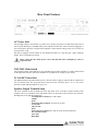
Clever Features, Contactor Friendly
AMIS250
250w Mixer Amplifier
Operating Manual
AMIS250, 250 Watt Mixer Amplifier
Product Description
The AMIS250 mixer amplifier is designed for commercial installations. It operates on 230 VAC, 50Hz and
may be desk or rack mounted (rack mount kit supplied). The AMIS250 delivers 250 watts into a load of 4
ohms, 70 or 100 volt line. As standard, the AMIS250 is supplied self standing with rubber feet. It features 6
microphone/line input channels as well as a host of unique features including multiple levels of muting and
24 VDC make the AMIS250 a very flexible amplifier.
.
Front Panel Features
Microphone/Line Level Controls
The 6 dual mic/line input controls are labelled Ch 1 through to Ch 6 and should be adjusted to provide the
required level mix for each individual channel. Start with the controls set to level 0 and turn the controls
clockwise until the desired mix level for each channel is reached.
Bass Control
Setting this control in the centre position will give an overall flat bass response. Adjusting the bass control
in a clockwise direction will provide up to 12 dB of bass boost @ 100 Hz. Adjusting the bass control in a
counter-clockwise direction will provide up to -12 dB of bass cut @ 100 Hz.
Middle Control
Setting this control in the centre position will give an overall flat middle response. Adjusting the mid
control in a clockwise direction will provide up to 12 dB of mid boost @ 600 Hz. Adjusting the mid
control in a counter-clockwise direction will provide up to -12 dB of mid cut @ 600 Hz.
Treble Control
Setting this control in the centre position will give an overall flat treble response. Adjusting the treble
control in a clockwise direction will provide up to 9 dB of treble boost @ 10kHz. Adjusting the treble
control in a counter-clockwise direction will provide up to -9 dB of treble cut @ 10 kHz.
Master Output Control
The Master level pot controls the overall output level of the amplifier depending on the levels set for the
individual input channels as detailed above. Start with the control set to level 0 and turn clockwise until the
desired output level of the amplifier is reached.
Power Switch
This switch controls the switching of AC power to the amplifier. A blue ‘On’ LED will indicate whether
the amplifier is switched on or off. This switch will not switch DC power on or off in DC operation. In DC
operation mode, the amplifier is always on and the blue power LED will always be illuminated.
Protect LED
A feature of the AMIS250 is high temperature protection. In most applications, the internal cooling fan will
most probably never switch on. When used with demanding speaker loads or in difficult operating
environments, the fan may regularly switch on to cool the amp down and then switch off again. This
switching on and switching off is quite normal. The “Protect” function is there to protect the amplifier from
a high temperature problems which would only occur if the fan stopped working or became clogged up. In
this very rare occurance, the amplifier will shut down and the protect LED will illuminate. The amplifier
will automatically restart once it’s internal temperature has fallen within “safe” limits. If the protect LED
illuminates, it is best to switch the amplifier off, let it cool down and then try it again. If the protect LED
illuminates again, please contact the company who supplied or installed the equipment.
Rear Panel Features
AC Power Inlet
The operating voltage is 230/240 VAC @ 50 Hz. The 3 pin IEC power inlet is located on the bottom left of
the rear panel and accepts a standard mains power lead fitted with an IEC connector. Before plugging in a
power lead, please check the rear panel of the amplifier to ensure that the voltage switch is set correctly for
your part of the world.
The inlet is equipped with an in-built AC fuse holder fitted with a 6.3 amp fuse plus a spare within the
holder. Power consumption is 400 VA.
Please ensure that the mains power cord is disconnected before attempting to check or
replace this fuse.
230V/240V Slide Switch
The operating voltage of the amplifier is user selectable between 230V and 240V via a slide switch located
on the right of the AC inlet. This switch should be set to match the AC voltage of your country
24 Volt DC Power Inlet
The AMIS250 features optional 24VDC power to run off a battery supply if required. This is connected via
the rear terminal strip. The front panel Power Switch will not switch DC power ‘on’ or ‘off’ in DC
operation. In this mode the amplifier is always ‘on’.
Speaker Output Terminal Strip
The screw terminals on the left hand side of the strip allow access to the direct speaker outputs of the
amplifier. The screw terminals on the right hand side are for activation of the in-built 4 tone generator.
Reading from left to right the terminals are:
Low Impedance Common (use with 4 ohms)
4 Ohms
Spare
Constant Voltage Common (use with 70v or 100v)
70 Volt Line
100 Volt Line
Spare
Tone Generator Common (use with one of the 4 tones listed below)
Pre-Announce Chime
Alert Tone
Bell Chime
Evacuation Tone
Note: The minimum impedance (or maximum load) at 100 Volt line should be no less than 40 Ohms.
Phantom Power
This button enables or disables the 18 volts DC phantom power which is available on all microphone inputs
(XLR’s). The “in” position indicates that phantom power is on for all mics. The “out” position means that
phantom power is switched off for all mics. Phantom power is required for electret condenser microphones
which require DC power to operate. While some of these microphones can operate from an internal battery,
having phantom power available on the amplifier eliminates the need to regularly change batteries in the
microphone. While phantom power is not required for the more common Dynamic microphones, it will not
damage them providing that they are balanced. Do not plug an unbalanced microphone in any amplifier or
mixer when phantom power is switched on.
Line Output
The balanced XLR line level output provides a maximum of 700mV to allow for connection to up to 6
power amplifiers. Simply run a balanced cable from the line out of the AMIS250 to the line input of the
power amplifier. Pin connections are: pin #1-earth; pin #2-signal (high, +); pin #3-signal (low, -).
Tape Output
Dual RCA output connectors provide a line level output with a maximum of 350mV into 10K Ohms which
is ideal for a connection to most standard tape recorders. This output is sourced before the master gain
control and as such, the tape output level is not influenced by the operation of the master gain control.
Microphone Inputs
The mic input sensitivity is 1mV @ 200 ohms. Pin connections are: pin #1-earth; pin #2-signal (high, +);
pin #3-signal (low, -). Phantom power of +15 volts is available on all microphone inputs. Reading from
left to right across the rear panel, the connection are for microphone inputs 6, 5, 4, 3, 2, & 1 respectively.
Line Inputs
Line inputs 1, 2, 3, 4, & 5 have an input sensitivity of 150mV @ 100K ohms. Input 6 has an input
sensitivity of 300mV @ 220K ohms making it suitable for high level inputs such as a CD player. Reading
from left to right across the rear panel, the connections are for inputs 6, 5, 4, 3, 2, & 1 respectively.
Other Features
Tone Generator
Four separate tones are available from the in-built tone generator board. All four tones can
be activated individually via a contact closure connected to the screw terminals on the rear
of the amplifier. To activate the bell chime for example, just run a pair of wires from the
Tone generator common and the Bell terminal to an external switch. Activating the switch,
or closing the pair of wires, will activate the bell. When any tone is activated, all inputs (except for inputs
one and two) will automatically mute. To adjust the level of the tone generator, disconnect the power lead,
remove the amplifier lid and locate the pot labeled R6. (located behind the Bass adjustment pot). This pot
adjusts the level for all 4 tones.
Tones available on the AMIS250 include:
Evacuation Tone
Alert Tone
Bell Tone
Pre-Announce Chime
Muting
A VOX muting card is installed in the AMIS250. This feature provides automatic muting
of some channels when others are active. It is normally used so that a paging microphone
can have priority (by muting) over background music. VOX muting is available from
channels 1 and 2 meaning that any signal on channels 1 and 2 (mic or line) will mute
channels 3, 4, 5 & 6. The muted channels will automatically ramp back up to normal
volume when the signal on channels 1 and/or 2 is no longer active. The amplifier ships with the VOX
muting function enabled. To disable the VOX muting, disconnect the mains power lead and remove the lid
of the amplifier. Looking down from the front of the amplifier, a three position jumper (labeled JP2) is
located just to the left and behind the level pot for channel 1. To disable VOX muting, move the jumper to
the middle and left pins.
(The factory setting is with VOX enabled with the jumper on the middle and right pins).
Insert Point
The AMIS250 includes an Insert Point to allow for connection of signal processors such as equalisers,
compressors or Feedback Exterminators. The Insert Point is located (electronically) between the mixer and
power amplifier sections of the AMIS250. It allows for the “mixed” output of the AMIS250 to be
processed externally and then returned to the power amplifier section of the AMIS250.
The Insert Point is a 3 conductor (Tip, Ring, Sleeve) socket which accepts a standard stereo 6.35mm (1/4”)
jack. The one jack allows for signals to be “sent” to the processor and then “returned” to the power
amplifier. The connections are:
Tip
Amplifier in. This is the return signal from the processor
Ring
Mix Output. This is the signal from the mixer stage which is to be sent to the processor
Sleeve This is the ground connection
When an external processor is used via the insert point, it only affects the power amplifier section of the
AMIS250. The tape output remains unprocessed.
Fuse Sizes
Mains, 230 VAC: 6.3 Amperes Slow Blow
DC: 10 Amperes Slow Blow
Notes:
The DC fuse is located on the circuit board. This is a feature of the AMIS series amplifier,
which is equipped with a current limiting circuit preventing excessive DC current, thus
eliminating the risk of blowing high tensions fuses. In the unlikely event that the DC fuse
actuates, the output transistors should be checked, as it is probable that the amplifier has been subjected to
very extreme conditions.
Important Safety Information
1. Save the carton and packing material even if the equipment has arrived in good condition. Should
you ever need to ship the unit, use only the original factory packing.
2. Read all documentation before operating your equipment. Retain all documentation for future
reference.
3. Follow all instructions printed on unit chassis for proper operation.
4. Do not spill water or other liquids into or on the unit, or operate the unit while standing in liquid.
5. Make sure power outlets conform to the power requirements listed on the back of the unit.
6. Do not use the unit if the electrical power cord is frayed or broken. The power supply cords should
be routed so that they are not likely to be walked on or pinched by items placed upon or against them,
paying particular attention to cords and plugs, convenience receptacles, and the point where they exit from
the appliance.
7. Always operate the unit with the AC ground wire connected to the electrical system ground.
Precautions should be taken so that the means of grounding of a piece of equipment is not defeated.
8. Mains voltage must be correct and the same as that printed on the rear of the unit. Damage caused
by connection to improper AC voltage is not covered by any warranty.
9. Have gain controls on amplifiers turned down during power-up to prevent speaker damage if there
are high signal levels at the inputs.
10. Power down & disconnect units from mains voltage before making connections.
11. Never hold a power switch in the “ON” position if it won’t stay there itself!
12. Do not use the unit near stoves, heat registers, radiators, or other heat producing devices.
13. Do not block fan intake or exhaust ports. Do not operate equipment on a surface or in an
environment which may impede the normal flow of air around the unit, such as a bed, rug, weathersheet,
carpet, or completely enclosed rack. If the unit is used in an extremely dusty or smoky environment, the
unit should be periodically “blown free” of foreign matter.
14. Do not remove the cover. Removing the cover will expose you to potentially dangerous voltages.
There are no user serviceable parts inside.
15. Do not drive the inputs with a signal level greater than that required to drive equipment to full
output.
16. Do not connect the inputs / outputs of amplifiers or consoles to any other voltage source, such as a
battery, mains source, or power supply, regardless of whether the amplifier or console is turned on or off.
17. Do not run the output of any amplifier channel back into another channel’s input. Do not
parallel- or series-connect an amplifier output with any other amplifier output.
Australian Monitor is not responsible for damage to loudspeakers for any reason.
18. Do not ground any red (“hot”) terminal. Never connect a “hot” (red) output to ground or to
another “hot” (red) output!
19. Non-use periods. The power cord of equipment should be unplugged from the outlet when left unused
for a long period of time.
20. Service Information Equipment should be serviced by qualified service personnel when:
A. The power supply cord or the plug has been damaged.
B. Objects have fallen, or liquid has been spilled into the equipment
C. The equipment has been exposed to rain
D. The equipment does not appear to operate normally, or exhibits a marked change in performance
E. The equipment has been dropped, or the enclosure damaged.
Engineered in Sydney, Australia
www.australianmonitor.com.au
International Sales & Corporate Head Office
Private Bag 149, Silverwater NSW 1811
149 Beaconsfield Street, Silverwater NSW 2128
Australia
Ph: 61-2- 9647 1411
Fax: 61-2-9748 2537
E-mail: [email protected]