1
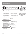
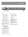
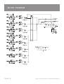
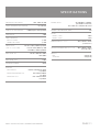
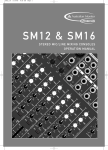
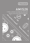
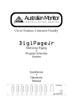
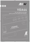
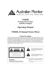
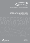
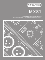
MX81
8 CHANNEL MIC/LINE MIXER
INSTALLATION AND OPERATION MANUAL
HEADING
1.
IMPORTANT SAFETY INFORMATION
Save the carton and packing material even if the equipment has
arrived in good condition. Should you ever need to ship the unit,
use only the original factory packing.
2. Read all documentation before operating your equipment.
Retain all documentation for future reference.
3. Follow all instructions printed on unit chassis for proper operation.
4. Do not spill water or other liquids into or on the unit, or operate the
unit while standing in liquid.
5. Make sure power outlets conform to the power requirements listed
on the back of the unit.
6. Do not use the unit if the electrical power cord is frayed or broken.
The power supply cords should be routed so that they are not likely
to be walked on or pinched by items placed upon or against them,
paying particular attention to cords and plugs, convenience
receptacles, and the point where they exit from the appliance.
7. Always operate the unit with the AC ground wire connected to the
electrical system ground. Precautions should be taken so that the
means of grounding of a piece of equipment is not defeated.
8. Mains voltage must be correct and the same as that printed on the
rear of the unit. Damage caused by connection to improper AC
voltage is not covered by any warranty.
9. Have gain controls on amplifiers turned down during power-up to
prevent speaker damage if there are high signal levels at the
inputs.
10. Power down & disconnect units from mains voltage before making
connections.
11. Never hold a power switch in the “ON” position if it won’t stay
there itself!
12. Do not use the unit near stoves, heat registers, radiators, or other
heat producing devices
13. Do not block fan intake or exhaust ports. Do not operate
equipment on a surface or in an environment which may impede
the normal flow of air around the unit, such as a bed, rug,
weathersheet, carpet, or completely enclosed rack. If the unit
is used in an extremely dusty or smoky environment, the unit
should be periodically “blown free” of foreign matter.
14. Do not remove the cover. Removing the cover will expose you to
potentially dangerous voltages. There are no user serviceable
parts inside.
15. Do not drive the inputs with a signal level greater than that
required to drive equipment to full output.
16. Do not connect the inputs / outputs of amplifiers or consoles to
any other voltage source, such as a battery, mains source, or
power supply, regardless of whether the amplifier or console is
turned on or off.
17. Do not run the output of any amplifier channel back into another
channel’s input. Do not parallel- or series-connect an amplifier
output with any other amplifier output.
Australian Monitor Inc is not responsible for damage to
loudspeakers for any reason.
18. Do not ground any red (“hot”) terminal. Never connect a “hot”
(red) output to ground or to another “hot” (red) output!
19. Non-use periods. The power cord of equipment should be unplugged
from the outlet when left unused for a long period of time.
20. Service Information Equipment should be serviced by qualified
service personnel when:
A.
B.
C.
D.
E.
The power supply cord or the plug has been damaged.
Objects have fallen, or liquid has been spilled into the
equipment
The equipment has been exposed to rain
The equipment does not appear to operate normally,
or exhibits a marked change in performance
The equipment has been dropped, or the enclosure damaged.
THIS SAFETY INFORMATION IS OF A GENERAL NATURE AND MAY BE SUPERSEDED BY INSTRUCTIONS CONTAINED WITHIN THIS MANUAL
INTRODUCTION AND CONTENTS
The MX81 is an 8 channel audio mixer that operates from 110/230-240
VAC @ 50/60 Hz or 24 VDC via an external 24VDC supply.
The MX81 offers high quality audio performance & a wide array of
features in a standard 1 RU size. For table mounting, rubber feet are
supplied but these can be removed if rack mounting is intended.
INTRODUCTION
3
FRONT PANEL
4
REAR PANEL
5
INTERNAL ADJUSTMENTS
6
There are eight dual purpose inputs consisting of balanced XLR inputs
switchable between mic & line level and dual RCA aux/line level
inputs. Each input has front panel trim control, status LED and bass
& treble controls.
INSTALLATION & TROUBLESHOOTING
7
BASIC SETUP & OPERATION
8
Priority muting is available as an optional addition as is remote
VCA master control and tone generation.
DIMENSIONS
9
The MX81 also features 4 segment LED output metering & the ability
to internally switch input 1 to be either pre or post master.
BLOCK DIAGRAM
10
SPECIFICATIONS
11
With both Headphone out & Record out also available the MX81
is extremely versatile & represents excellent value for money.
Thankyou for purchasing the Australian Monitor Installation
Series MX81.
AUS, EUR, USA
Copyright 24th Jan 2006
Rev A 24/01/06
This symbol is intended to alert the user to the presence
of uninsulated “dangerous voltage” within the product’s
enclosure that may be of sufficient magnitude to
constitute a risk of electric shock to persons.
This symbol is intended to alert the user to the presence
of important operation and maintenance (servicing)
instructions in the literature accompanying the appliance.
Caution:
MX81 INSTALLATION & OPERATION MANUAL
To prevent electric shock do not use this (polarised) plug
with an extension cord, receptacle or other outlet unless
the blades can be fully inserted to prevent blade exposure.
To prevent electric shock, match wide blade of plug to
wide slot, fully insert.
PAGE 3
FRONT PANEL
5
4
1
8
2
3
1 GAIN TRIM
This control is used to adjust the input
gain and affects both the XLR and the
RCA inputs. The input gain can be
adjusted by +/- 15dB. This allows a wide
rage of program sources to be set up with
optimum gain structure. With the gain trim
in the centre position, the boost/cut is set
to 0dB. See the block diagram on page 10
for details of the gain structure.
10
6
7
9
10 POWER ON LED
5 MIC / LINE
Each input has a switch which controls
the sensitivity of the XLR input. In the
off/out or "MIC" position the XLR input is
suitable for use with microphones; in the
on/in or "LINE" position the XLR input is
suitable for use with a balanced line level
signal. Note: The Mic/Line switches only
affect the XLR input.
This indicates there is power to the unit.
☛
NOTE: When using the 24VDC
socket the power LED will
always be on.
6 MASTER
2 LEVEL
This pot controls the overall mixed output.
Controls the level of the input signal.
3 INPUT STATUS LEDS
Each input has an LED status indicator.
The LED is green when there is signal
present and red if the signal is
approaching clip. If the LED begins to light
red this would indicate the internal signal
level is 6dB before clip. Note that the front
panel level control is post status LED and
as such, the status LED is NOT affected
by the level control. If an input channel is
clipping use the gain control to adjust
the correct amount of input level.
4 CHANNEL TONE CONTROLS
Each input has a 2 band EQ.
Bass – +/-12dB 100Hz shelving
Treble – +/-12dB 10kHz shelving
PAGE 4
7 HEADPHONE
This 1⁄4” jack socket allows headphones
to be used for monitoring. It can be set
as pre or post master volume control.
See “Internal Adjustments” on page 6.
Default factory setting is pre master
volume control.
8 MASTER VU DISPLAY
This VU display indicates output level.
9 POWER SWITCH
This switch switches power from the
mains. The up position is on.
☛
NOTE: When using the 24VDC
socket the unit is on regardless
of switch position.
MX81 INSTALLATION & OPERATION MANUAL
REAR PANEL
4
5
6
3
2
1 CHANNEL INPUTS
Channels 1 to 6 have two inputs, channels
7-8 only have an XLR input:
XLR input - This is a balanced input.
It accepts mic or line level signals
depending on the front panel gain
switch position. The XLR will also
have +15V phantom power if
selected on the switch.
RCA input - This is an unbalanced line
level input. The two RCA sockets are
summed to mono internally.
2 REC OUT
The REC OUT output is on unbalanced
RCA connectors. The output is dual mono
and is not affected by the MASTER volume
control or the EQ tone controls.
3 OUTPUT
1
5 IEC MAINS INPUT SOCKET
This is a standard IEC 3 pin socket. It
accepts a standard IEC mains cable,
provided. The fuse draw contains the
mains fuse and a spare. The mains fuse is
a time lag (slow blow) HRC 20mm x 5mm
ceramic type fuse.
The ratings are:
230V/240V model 63mA
115V model 120mA
Always replace the fuse with
one of the same value and type.
NOTE: Always disconnect
power to the amplifier before
replacing fuses.
6 OPTIONAL MODULE INPUTS
This socket is used with a tone module
and/or VCA module.
The OUTPUT XLR provides balanced line
level signal.
☛
NOTE: When wiring the LINE
output as unbalanced, Pin2
should be wired as hot and
Pin1 should be wired as
ground/shield. Do not wire Pin3.
4 24VDC SOCKET
This 2.1mm x 5.5mm barrel socket is
provided for 24V emergency systems and
is not switched by the front panel power
switch. Note:The 24VDC socket does not
provide trickle charge facility. Tip of the
connector is positive.
MX81 INSTALLATION & OPERATION MANUAL
PAGE 5
INTERNAL ADJUSTMENTS
1
2
4
1 P/P – PHANTOM POWER
This switch is accessible through the lid of
the MX81. 15V phantom power is available
for condenser or electret microphones on
the XLR input when this switch is in the
’ON’ position.
2 CHANNEL 1 ROUTING
If channel 1 is being used as a priority
input it can be routed so that the master
volume does not affect channel 1.
The default factory setting is pre master
fader meaning the master volume affects
channel 1 in the mix. The jumper header
is located mid way above channel 1 pot.
Move the jumper to link the two pins
nearer the channel 1 pot to set channel 1
to post master fader.
PAGE 6
4
4
3
3 HEADPHONE ROUTING
The headphone level can be routed so
that it is affected by the master volume.
The default factory setting is pre master
fader meaning the master volume does
not affect the headphone volume.
The jumper header is located just behind
the front panel above the master pot.
Move the jumper to link the two pins
nearer the inputs to set the headphone
to post master fader.
4 OPTIONAL MODULES
The MX81 can have installed:
a VCA module
a Tone Generator module
a Priority Muting module
See your local Australian Monitor dealer
for more information.
MX81 INSTALLATION & OPERATION MANUAL
INSTALLATION & TROUBLESHOOTING
INPUT CONNECTIONS
For wiring balanced in, pin 2 is hot. Unbalanced wiring on the
microphone inputs is not recommended. Balanced input wiring
(shielded pair cable) is recommended.
Unbalanced RCA wiring should be keep as short as possible.
Typically less than 3m.
LINE OUTPUT
The LINE output XLR can be used to connect up to 6 booster amplifiers.
Balanced wiring (shielded pair cable) is recommended.
☛
NOTE: When wiring the LINE output as unbalanced,
Pin2 should be wired as hot and Pin1 should be wired
as ground/shield. Do not wire Pin3.
RECORD OUTPUT.
The Record output wiring should be kept as short as possible.
Typically less than 3m.
TROUBLE
LIKELY CAUSE
REMEDY
Power LED not on
Power not reaching unit
Check mains connection
Check mains fuse
Check power switch is on
Poor S/N ration
Incorrect gain structure
See setup guide
Distorted sound
Input is overloaded
Reduce input gain
Reduce input level at source
Output is being over driven
Reduce output volume
No sound but unit is on
Volume turned down
Check volume controls
Tones and/or VCA control does not work
Module not installed
Purchase optional modules
Condenser microphone does not work
Phantom power not switched on
Switch on phantom power
MX81 INSTALLATION & OPERATION MANUAL
PAGE 7
BASIC SETUP & OPERATION
The inputs of the MX81 can accommodate a wide range of sources
including dynamic microphones, DVD and CD players. The output
may be used to drive power (booster) amplifiers, other mixers or
mixer amplifiers.
Each installation will require setting the appropriate relative mix of
levels between microphones and program. Because of the variation
in levels between the possible sources, the MX61 offers a number of
gain stage adjustments so you can set the correct levels for your
application. Also consider what the output is driving . . .
Setting up correct gain structure through the whole system is
important to achieve optimal results. The following step by step
procedure has been devised to assist during the setup process.
When the MX61 was shipped to you from the factory, it was set up
in a particular way. In the following procedure it is essential that
you are starting from these initial settings.
• Program Input Gain Controls – half (12 o’clock)
• XLR Mic/Line switch – MIC
• XLR Phantom power - on
• Input Level Controls – off
• Output Level Control – off
STEP BY STEP SETUP
1 CONNECT THE SOURCES
First connect all the required sources to the appropriate input
connectors. If the source is a microphone, set the MIC/LINE
switches to the "MIC" position. If the source is an electret or
condenser microphone, set the phantom switch to the "P/P on"
position.
2 CONNECT THE OUTPUTS
Turn the amplifiers off. Connect the MX81 output to the amplifiers'
line level input. Check that the MX81 is on, and then turn on the
amplifiers. If the amplifiers have a level control, set them it to a
sensitivity of 0dBu. If in doubt, set it to maximum.
3 TEST THE INPUT LEVELS
For each source, try to achieve the highest signal level possible.
i.e. for a CD player, cassette deck or other music source, put on
the loudest anticipated program music or for a paging mic make a
‘loud’ page. During this signal condition, the input status LED should
light green and may occasionally turn red for a short period.
If the status LED stays red (more than 10% of the time), you should
reduce the input gain trim. If the status LED never turns red at all,
you may wish to increase the input gain trim if required.
4 SET THE LEVELS
Turn the input levels up to 5. Turn up the output level until it is
at an appropriate level for the listening environment. You will
now have to adjust the relative levels of the inputs to achieve a
good balance. The aim of these adjustments is to have all level
controls at between 3 and 7. This may not be possible however.
A good rule of thumb is that input level controls should be higher
than the output level controls.
PAGE 8
MX81 INSTALLATION & OPERATION MANUAL
DIMENSIONS
MX81 INSTALLATION & OPERATION MANUAL
PAGE 9
BLOCK DIAGRAM
PAGE 10
MX81 INSTALLATION & OPERATION MANUAL
SPECIFICATIONS
20Hz - 20kHz (+0,-3dB)
FREQUENCY RESPONSE
TOTAL HARMONIC DISTORTION
SIGNAL TO NOISE RATIO
CROSSTALK
TONE CONTROLS
BASS @ 100HZ
TREBLE @ 10KHZ
SENSITIVITY
(Trim in centre 0dB)
MAX LEVEL IN
< 0.1% @ 1kHz
> 90dB (all pots at centre position)
>70dB
+/- 12dB
+/- 12dB
Mic Sens 4.36mV, -45dBu Imp 1k3ohm
Line Sens 0.775V, 0dBu Imp >100k
RCA 200mV, -12dBu Imp 30kohm
XLR mic -15dBu line +30dBu
RCA >30dBu
MAX LEVEL OUT
+21dBu
PHANTOM POWER
15V DC
OUTPUTS
MASTER OUT
MONO HEADPHONE OUT
MONO REC OUT
POWER INPUT
AC: 230V/50Hz or 115V/60Hz,
3 pin IEC320-C14 connector;
DC: 24 Volts via 2.1mmx5.5mm DC socket
POWER CONSUMPTION (MAX)
FUSES
MAINS (115V)
MAINS (230V)
7 VA
120mA
63mA
DIMENSIONS h x w x d
44mm x 482mm x 182mm
(1.75“x19”x7.2”)
SHIPPING DIMENSIONS h x w x d
90mm x 505mm x 270mm
(3.5“x19.9”x10.6”)
WEIGHT
NET
SHIPPING
2.75kg (6.1lb)
3.75kg (8.3lb)
Nominal Level 0dBu into 1kohm
Imp 100ohm
Nom -6dB into 200ohm
Imp 10ohm
Nom -12dB into 10kohm
Imp 10kohm
MX81 INSTALLATION & OPERATION MANUAL
PAGE 11
AUSTRALIA AND NEW ZEALAND
www.australianmonitor.com.au
SYDNEY
MELBOURNE
BRISBANE
ADELAIDE
PERTH
AUCKLAND
(NSW & ACT SALES)
(VIC & TAS SALES)
(QLD SALES)
(SA & NT SALES)
(WA SALES)
(NZ SALES)
149 Beaconsfield
Street Silverwater
NSW 2128
Private Bag 149
Silverwater NSW 1811
Phone: (02) 9647 1411
Fax: (02) 9648 3698
Email:
[email protected]
22/277
Middleborough Road
Box Hill VIC 3128
PO Box 151 Blackburn
South VIC 3130
Phone: (03) 9890 7477
Fax: (03) 9890 7977
Email:
[email protected]
42 Commercial Road
Fortitude Valley
QLD 4006
PO Box 871 Fortitude
Valley QLD 4006
Phone: (07) 3852 1312
Fax: (07) 3252 1237
Email:
[email protected]
31 Walsh Street
Thebarton
SA 5031
PO Box 157
Hindmarsh SA 5007
Phone: (08) 8352 4444
Fax: (08) 8352 4488
Email:
[email protected]
299 Fitzgerald Street
West Perth WA 6005
PO Box 404
North Perth
WA 6906
Phone: (08) 9228 4222
Fax: (08) 9228 4233
Email:
[email protected]
Unit B, 11 Piermark
Drive Albany 1331
New Zealand
PO Box 512
Albany 1331
Phone: (09) 415 9426
Fax: (09) 415 9864
Email:
[email protected]
EUROPE/ASIA/MIDDLE EAST
USA/SOUTH AMERICA
www.australianmonitor.com.au
www.australianmonitor.com
INTERNATIONAL SALES
SENNHEISER ELECTRONIC CORPORATION
149 Beaconsfield Street Silverwater NSW 2128 Australia
Private Bag 149 Silverwater NSW 1811
Phone: 61 2 9647 1411
Fax: 61 2 9648 3698
Email: [email protected]
1 Enterprise Drive
Old Lyme CT 06371 USA
Phone: 1 860 434 9190
Fax: 1 860 434 1759
Email: [email protected]