1
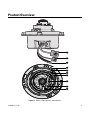
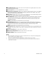
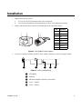
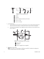
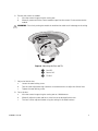
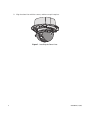
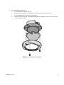
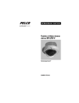
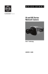
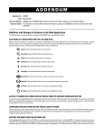
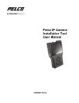
Q U I C K
S T A R T
IM-E/IM-V Series
Network Dome Camera
Sarix™ Technology
C2983M-A (12/10)
Contents
Product Overview . . . . . . . . . . . . . . . . . . . . . . . . . . . . . . . . . . . . . . . . . . . . . . . . . . . . . . . . . . . . . . . . . . . . . . 3
Installation . . . . . . . . . . . . . . . . . . . . . . . . . . . . . . . . . . . . . . . . . . . . . . . . . . . . . . . . . . . . . . . . . . . . . . . . . . . 5
Operation . . . . . . . . . . . . . . . . . . . . . . . . . . . . . . . . . . . . . . . . . . . . . . . . . . . . . . . . . . . . . . . . . . . . . . . . . . .
IP Address Settings . . . . . . . . . . . . . . . . . . . . . . . . . . . . . . . . . . . . . . . . . . . . . . . . . . . . . . . . . . . . . .
Minimum System Requirements . . . . . . . . . . . . . . . . . . . . . . . . . . . . . . . . . . . . . . . . . . . . . . . . . . . .
Live Page Icons. . . . . . . . . . . . . . . . . . . . . . . . . . . . . . . . . . . . . . . . . . . . . . . . . . . . . . . . . . . . . . . . . .
Settings Page . . . . . . . . . . . . . . . . . . . . . . . . . . . . . . . . . . . . . . . . . . . . . . . . . . . . . . . . . . . . . . . . . . .
System Tab . . . . . . . . . . . . . . . . . . . . . . . . . . . . . . . . . . . . . . . . . . . . . . . . . . . . . . . . . . . . . . . .
Network Tab . . . . . . . . . . . . . . . . . . . . . . . . . . . . . . . . . . . . . . . . . . . . . . . . . . . . . . . . . . . . . . .
Imaging Tab . . . . . . . . . . . . . . . . . . . . . . . . . . . . . . . . . . . . . . . . . . . . . . . . . . . . . . . . . . . . . . .
A/V Streams Tab . . . . . . . . . . . . . . . . . . . . . . . . . . . . . . . . . . . . . . . . . . . . . . . . . . . . . . . . . . .
Users Tab . . . . . . . . . . . . . . . . . . . . . . . . . . . . . . . . . . . . . . . . . . . . . . . . . . . . . . . . . . . . . . . . .
Events Tab . . . . . . . . . . . . . . . . . . . . . . . . . . . . . . . . . . . . . . . . . . . . . . . . . . . . . . . . . . . . . . . .
10
10
10
11
12
12
12
13
14
14
15
List of Illustrations
1
2
3
4
5
6
7
8
Camera Connections and Features . . . . . . . . . . . . . . . . . . . . . . . . . . . . . . . . . . . . . . . . . . . . . . . . . . .
Cat5 Cable Pin Descriptions. . . . . . . . . . . . . . . . . . . . . . . . . . . . . . . . . . . . . . . . . . . . . . . . . . . . . . . . .
Line-In Audio Wiring . . . . . . . . . . . . . . . . . . . . . . . . . . . . . . . . . . . . . . . . . . . . . . . . . . . . . . . . . . . . . .
Line-Out Audio Wiring . . . . . . . . . . . . . . . . . . . . . . . . . . . . . . . . . . . . . . . . . . . . . . . . . . . . . . . . . . . . .
Fixed Ceiling or Wall Installation . . . . . . . . . . . . . . . . . . . . . . . . . . . . . . . . . . . . . . . . . . . . . . . . . . . . .
Adjusting the Pan and Tilt . . . . . . . . . . . . . . . . . . . . . . . . . . . . . . . . . . . . . . . . . . . . . . . . . . . . . . . . . .
Installing the Dome Liner . . . . . . . . . . . . . . . . . . . . . . . . . . . . . . . . . . . . . . . . . . . . . . . . . . . . . . . . . . .
Installing the Lower Dome . . . . . . . . . . . . . . . . . . . . . . . . . . . . . . . . . . . . . . . . . . . . . . . . . . . . . . . . . .
3
5
5
6
6
7
8
9
The materials used in the manufacture of this document and its components are compliant to the requirements of
Directive 2002/95/EC.
This equipment contains electrical or electronic components that must be recycled properly to comply with
Directive 2002/96/EC of the European Union regarding the disposal of waste electrical and electronic equipment
(WEEE). Contact your local dealer for procedures for recycling this equipment.
2
C2983M-A (12/10)
Product Overview
Figure 1. Camera Connections and Features
C2983M-A (12/10)
3
ì RJ-45 Network Port: Connects the camera to the IP network. Also supplies power to the camera
through the network using PoE.
î Accessory Port: For use with compatible Pelco accessories.
ï Audio Line-In and Line-Out: Supplies line-in and line-out audio connections from a user-supplied
device. Audio functionality is only available for IM10-E and IM10-V Series models, and it can be
enabled or disabled using the Web browser.
ñ Microphone: Supplies built-in, line-in audio to a PC. Microphone is only available for IM10-V Series
models, and it can be enabled or disabled using the Web browser.
ó Reset Button (R): Reboots the camera or restores the camera’s factory default settings. This button
is recessed. Using a small tool, such as a paper clip, press and release the reset button once to
reboot the camera. Press and hold the reset button for 10 seconds to restore the camera to the
factory default settings.
NOTE: The lower dome must be removed to access this button.
r NTSC/PAL Button (V): Toggles the service port between NTSC and PAL formats. This button is
recessed. Using a small tool, such as a paper clip, press and release the NTSC/PAL button to toggle
between NTSC and PAL formats when using the service port. The default setting is NTSC.
NOTE: The lower dome must be removed to access this button
s Service Port: Outputs analog video. Use this port at the installation site to set up the field of view
and to focus the camera. When a service cable is connected to the camera, video to the IP stream is
disabled.
t Zoom Locking Screw: Sets the camera’s field of view.
u Manual Focus Adjustment: Manually adjusts the focus of the camera.
~í IMAGE UP Mark: Displays the position of the camera.
NOTES:
•
Pelco recommends connecting the camera to a network that uses a Dynamic Host Configuration
Protocol (DHCP) server to address devices.
•
Do not use a network hub when configuring the network settings for the camera.
•
To ensure secure access to the network camera, place the camera behind a firewall when it is
connected to a network.
4
C2983M-A (12/10)
Installation
1. Prepare the mounting surface:
a.
Cut a 4-inch (10.16 cm) diameter hole in the ceiling/wall.
b.
Pull all wiring through the hole and terminate all wires (if not already terminated).
2. Connect the network cable to the RJ-45 network port on the side of the camera.
Pin
1
1
8
8
2
3
4
5
6
7
1
8
8
7
6
Function
1
TX+
2
TX–
3
RX+
4
PoE 1-2
5
PoE 1-2
6
RX–
7
PoE 3-4
8
PoE 3-4
5
4
3
2
1
Figure 2. Cat5 Cable Pin Descriptions
3. If you are installing an IM10-V or IM10-E Series model, connect the necessary wiring for audio.
+
–
Figure 3. Line-In Audio Wiring
ì Microphone
î Amplifier
ï 600-Ohm Impedance Matching Transformer
ñ Line In – (White)
ó Line In + (Brown)
C2983M-A (12/10)
5
+
–
Figure 4. Line-Out Audio Wiring
ì Speaker
î Amplifier
ï 600-Ohm Impedance Matching Transformer
ñ Line Out – (Red)
ó Line Out + (Orange)
4. Install the back box:
a.
Insert the back box into the hole in the ceiling/wall. Be sure to angle the back box during this
step to ensure that the wiring is inserted into the hole first and is not bent or damaged.
b.
Use two 3/16-inch toggle bolts (not supplied) to attach the back box to the mounting surface
(refer to Figure 5).
Figure 5. Fixed Ceiling or Wall Installation
ì Ceiling/Wall
î Back Box
ï 3/16-inch Toggle Bolts (not supplied)
5. Apply power to the camera.
NOTE: If the camera is not connected to a DHCP server and DHCP is enabled, the configuration
sequence might take up to five minutes to complete.
6
C2983M-A (12/10)
6. Position the camera as needed:
a.
View the camera image using the service port.
b.
Manually rotate and tilt the camera module to position the camera. Do not over-rotate the
module.
WARNING: Excessively turning the module in one direction could result in damage to the wiring.
Figure 6. Adjusting the Pan and Tilt
ì Pan 355°
î Rotate 120°
ï Tilt 164°
7. Adjust the field of view:
a.
Loosen the zoom locking screw.
b.
Turn the zoom adjustment ring clockwise or counterclockwise to adjust the field of view.
c.
Tighten the zoom locking screw.
8. Focus the lens:
a.
View the camera image using the service port or a Web browser.
b.
Manually adjust the zoom and focus of the lens to the desired field of view.
c.
The focus can be adjusted further using the settings in the Web interface.
C2983M-A (12/10)
7
9. Align the dome liner with the camera, and then snap it into place.
Figure 7. Installing the Dome Liner
8
C2983M-A (12/10)
10. Install the bubble and trim ring:
a.
Place the bubble inside the trim ring.
b.
Align the trim ring screws with the three mounting screw holes on the back box.
c.
Push the bubble and trim ring onto the back box.
d.
Use the 1/8-inch hollow hex bit (supplied) to tighten the tamper-resistant screws to secure the
trim ring to the back box.
Figure 8. Installing the Lower Dome
C2983M-A (12/10)
9
Operation
IP ADDRESS SETTINGS
If the camera is connected to a Dynamic Host Configuration Protocol (DHCP) network and DHCP is set to
the On position, the server will automatically assign an IP address to the device; DHCP On is the default
setting for the camera. Set DHCP to the Off position to manually set the camera’s IP address.
NOTES:
•
If the camera is not connected to a DHCP server but DHCP is set to On, the default IP address
192.168.0.20 on subnet mask 255.255.255.0 is automatically assigned to the camera. After the first
camera is connected and assigned the default IP address, the system will automatically look for
other cameras on the auto IP address system and assign IP addresses in sequential order as
required.
For example, if three cameras are connected to a network without a DHCP server, the first camera is
assigned address 192.168.0.20, the second camera is assigned address 192.168.0.21, and the third
camera is assigned address 192.168.0.22.
•
•
Contact your network administrator to avoid network conflicts before setting or changing the
camera’s IP address.
If you do not know the camera’s IP address, install the Pelco Device Utility software available on the
resource disc supplied with the product. The utility will locate the assigned name, IP address, and
MAC address for devices connected to the same virtual local area network (VLAN) as your computer.
The Device Utility software is also available at www.pelco.com/software/downloads/.
MINIMUM SYSTEM REQUIREMENTS
The following minimum system requirements are needed to use a Web browser with the IP camera:
Processor: Intel® Pentium® 4 microprocessor, 1.6 GHz
Operating system: Microsoft® Windows® XP, Windows Vista®, or Mac® OS X 10.4
Memory: 512 MB RAM
Network interface card: 100 megabits (or greater)
Monitor: Minimum of 1024 x 768 resolution, 16- or 32-bit pixel color resolution
Web Browser: Internet Explorer® 7.0 (or later) or Mozilla® Firefox® 3.0 (or later)
NOTE: Internet Explorer is not supported by Mac OS X 10.4.
Media Player: Pelco’s Media Player or QuickTime® 7.6.5 for Windows XP, and Windows Vista, or
QuickTime 7.6.4 for Mac OS X 10.4 (or later).
NOTE: This product is not compatible with QuickTime version 7.6.4 for Windows XP, or Windows Vista.
If either operating system is installed on your computer, upgrade to QuickTime version 7.6.5.
10
C2983M-A (12/10)
LIVE PAGE ICONS
Viewable icons are based on group permissions.
Show Device List: Displays a list of viewable cameras connected to the same VLAN as the
camera to which you are logged on.
Disable Viewer: Closes the live view window.
1 x 1 Mode: Displays a single video pane.
2 x 2 Mode: Displays 4 video panes in rows of two.
3 x 3 Mode: Displays 9 video panes in rows of three.
4 x 4 Mode: Displays 16 video panes in rows of four.
Select Stream: Selects the viewable video stream that is displayed in live view (primary or
secondary) and selects unicast or multicast settings.
Maximize Viewing Area: Scales the image to the full size of the browser. To resize the video
pane to normal view, click the Show Toolbar button in the upper-right corner of the window.
Show Toolbar: Returns the window to normal view. This icon is only available after the
window has been set to maximize viewing area.
Open Stream in New Window: Opens the video in a scalable, independent window.
Opening the video in a separate window allows you to view the video while other applications
are running. This window can be minimized, maximized, or closed using the title bar buttons of
the active window. The window can also be resized to your specifications by dragging the
lower-right corner of the window.
Take a Snapshot: Captures the image displayed in the video pane and saves it as a JPEG file.
C2983M-A (12/10)
11
SETTINGS PAGE
Depending on user permissions, the Settings page allows you to manage camera system settings, set up
users and groups, and control the camera.
To access the camera settings:
1. Log on to the camera.
2. Click the Settings link in the navigation bar located in the upper-right corner of the page; a list of
menu tabs appear.
3. Place the mouse pointer over a tab to display a list of submenus.
SYSTEM TAB
General Settings: Includes configurable fields for the device name, time server, and text overlay settings.
You can also use the General Settings page to configure the Simple Mail Transfer Protocol (SMTP) server
to send an email notification when an event handler is activated.
System Information: Includes read-only fields for the firmware version, hardware version, model number,
and serial number of the system. This information is typically required by Pelco Product Support for
troubleshooting purposes.
NETWORK TAB
General: Displays the hardware address, hostname, DHCP settings, and IP address settings.
SSL: Secure Socket Layers (SSL) encrypts communications making it difficult for unauthorized users to
intercept and view user names and passwords.
SSH: Secure Shell (SSH) allows Pelco Product Support to log on to and service the camera for advanced
troubleshooting purposes.
802.1x: This standard authenticates devices that want to establish a point-to-point access through a wired
or wireless port using Extensible Authentication Protocol (EAP). This port-based authentication method
prevents unauthorized access to a Local Area Network (LAN) through a physical port.
SNMP: Simple Network Management Protocol (SNMP) manages TCP/IP-based networks from a single
workstation or several workstations. The camera supports SNMP versions 2c and 3 and can be configured
to send data using a trap.
12
C2983M-A (12/10)
IMAGING TAB
General: Includes camera orientation and digital processing settings. The orientation settings allow for
standard or inverted installation of the camera. The digital processing settings adjust the sharpness,
saturation, and contrast of the scene.
Exposure: Adjusts scene detail and contrast. A scene with correct exposure settings has adequate detail
and contrast between white and dark values. An image with too little or too much exposure eliminates
detail in the scene. The camera features auto and manual exposure settings.
Focus: Includes auto focus and manual focus settings (refer to Focus in the IM-E and IM-V Series
Installation/Operation manual for detailed instructions). Focus adjustment controls the focus of the lens.
Auto focus automatically adjusts the focus on a subject at the center of the scene. Manual focus turns off
the auto focus mechanism and locks the camera at a user-specified position. The manual focus setting is
recommended only for indoor applications that have a single, unchanging primary light source.
Tone Map: Balances the brightest and darkest sections of an image to produce a picture with more
balanced lighting and more detail.
White Balance: Defines how the camera processes video images to render true colors in a scene. White
balance is especially effective in scenes with changing lighting conditions or in scenes with more than one
type of light source.
Window Blanking: Conceals user-defined privacy areas. A blanked area appears on the screen as a solid
gray window. The camera can handle up to four blanked windows as long as the total blanked area does
not exceed 50 percent of the field of view.
C2983M-A (12/10)
13
A/V STREAMS TAB
Use the A/V Streams tab to configure the video and audio streams for the camera. The A/V Streams tab
includes a Video Presets page, a Video Configuration page, and an Audio Configuration page.
Video Presets: The Video Preset page includes three fully-configured video presets, which include
primary and secondary video stream settings for easy setup. These presets may also be used as a starting
point for a custom video configuration. These preset configurations vary depending on camera model.
Video Configuration: The Video Configuration page allows you to customize the compression, resolution,
image rate, and bit rate of the video streams. The default names for the streams are Primary Stream and
Secondary Stream. Although each stream can be configured independently, the settings of one stream can
limit the options available to the other stream, depending on the processing power used.
NOTE: Always configure the primary stream before the secondary stream. The primary stream should
always be the most resource-intensive of the streams.
Audio Configuration: The Audio Configuration page allows you to set up the internal audio device or an
external audio device. The default setting for Audio is disabled, which means that no audio is transmitted
from the camera. When enabled, audio is transmitted from the camera to the PC. Based on your system
configuration, images and audio may not be synchronized.
NOTES:
•
Improper use of audio/visual recording equipment may subject you to civil and criminal penalties.
Applicable laws regarding the use of such capabilities vary between jurisdictions and may require,
among other things, express written consent from the recorded subjects. You are solely responsible
for insuring strict compliance with such laws and for strict adherence to any/all rights of privacy and
personalty.
•
Not all camera models are equipped with an internal audio device. Refer to the specifications for
your camera model for information.
USERS TAB
General Settings: Changes the way the camera manages the users and groups settings. These settings
can be managed on a camera-to-camera basis or by using a centralized server to apply changes to multiple
cameras. Use the general settings page to set the public user access level. This access level is a
predefined set of user permissions that allow the camera to be accessed without logging on. The
permission levels are Operator, Viewer, and Disabled.
Users: Defines the permissions assigned to individuals logged on to the camera. The Users page also
includes four predefined access level settings: Administrator, Manager, Operator, and Viewer permissions.
14
C2983M-A (12/10)
EVENTS TAB
Sources: Defines the camera functions that are automatically triggered by an event source. The camera
supports Alarm, Analytics, System, and Timer event sources.
Handlers: Defines the actions that a camera takes when an event occurs. The camera supports four event
handlers: Send Email, Upload JPEG to FTP Server, and Open/Close Relay.
Analytic Configuration: Allows you to create custom profiles that contain different camera settings. The
IM-E and IM-V Series models are preloaded with Pelco’s Camera Sabotage behavior, which detects
contrast changes in the field of view. An alarm is triggered if the lens is obstructed with spray paint, a
cloth, or covered with a lens cap.
REVISION HISTORY
Manual #
C2983M
C2983M-A
Date
11/10
12/10
Comments
Original version.
Resized the document and added the access level settings to the Users Tab section.
Pelco, the Pelco logo, and other trademarks associated with Pelco products referred to in this publication are trademarks of Pelco, Inc. or its affiliates.
All other product names and services are the property of their respective companies.
Product specifications and availability are subject to change without notice.
© Copyright 2010, Pelco, Inc. All rights reserved.
C2983M-A (12/10)
15
www.pelco.com
Pelco by Schneider Electric 3500 Pelco Way Clovis, California 93612-5699 United States
USA & Canada Tel (800) 289-9100 Fax (800) 289-9150
International Tel +1 (559) 292-1981 Fax +1 (559) 348-1120