1
Dialogic® Diva® System Release 8.5LIN
Reference Guide
www.dialogic.com
Contents
Dialogic® Diva® System Release LIN Reference Guide
3
Syntax used throughout the guide........................................................................................ 3
Copyright and Legal Disclaimer
4
Software License Agreement
5
About the Dialogic® Diva® System Release Software
9
Features ............................................................................................................................. 9
System requirements......................................................................................................... 15
Installation and Configuration
15
Software installation .......................................................................................................... 16
Files included in the package ............................................................................................. 17
Configuring the Dialogic® Diva® System Release Software ................................................. 22
Loading the Dialogic® Diva® modules ............................................................................... 29
Dialogic® Diva® Media Board information.......................................................................... 29
Global fax configuration options ......................................................................................... 31
Special configuration features ............................................................................................ 33
Testing the Dialogic® Diva® Media Board functionality and connectivity............................... 33
Configuring the Dialogic® Diva® TTY ports
35
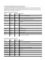
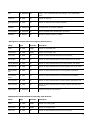
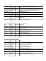
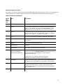
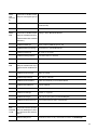
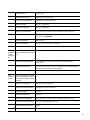
AT-command set............................................................................................................... 35
Supported TTY profiles ...................................................................................................... 52
Incoming RAS call type autodetection ................................................................................. 53
ASYNC/SYNC conversion module ........................................................................................ 54
Intelligent fax class 2 processing ........................................................................................ 54
Global Dialogic® Diva® TTY configuration options .............................................................. 57
Call parameter (BC/LLC) selection ...................................................................................... 57
TTY "channel pool" mode .................................................................................................. 58
"ESCAPE" sequence (+++) ................................................................................................ 59
AT-command responses..................................................................................................... 60
How to set up a dial-in server ............................................................................................ 64
How to set up a dial-in callback server ................................................................................ 66
How to set up a simple fax polling server (mgetty) .............................................................. 71
Uninstallation of the Dialogic® Diva® System Release Software
72
Unloading the Dialogic® Diva® driver modules:.................................................................... 72
Uninstalling the Dialogic® Diva® System Release Software ................................................... 72
1
Management interface
73
"divalogd" accounting utility ............................................................................................... 73
Management interface access and monitoring utility ............................................................ 74
Management interface structure ......................................................................................... 75
Dialogic® Diva® SNMPX extension agent
83
Requirements ................................................................................................................... 83
Configuration of the SNMP master agent............................................................................. 84
Activation of Dialogic® Diva® SNMP support ...................................................................... 84
Reference: Supported OIDs ............................................................................................... 85
Troubleshooting
88
Support procedure ............................................................................................................ 88
Dialogic® Diva® Trace Wizard .......................................................................................... 89
D-channel trace and health monitoring utility ...................................................................... 89
Dialogic® Diva® Media Board health monitoring utility........................................................ 93
XLOG trace and debug utility.............................................................................................. 93
tty_test utility ................................................................................................................... 95
Web interface
101
WEB server configuration..................................................................................................101
Login procedure ...............................................................................................................102
Context sensitive help.......................................................................................................102
Dialogic home page..........................................................................................................103
Reference Guide ..............................................................................................................103
Main page .......................................................................................................................104
Product Features
132
Supported interfaces ........................................................................................................132
Features of Dialogic® Diva® ISDN Media Boards via interface ............................................133
Supplementary services of Dialogic® Diva® ISDN Media Boards via interface ......................136
Supplementary services of Dialogic® Diva® ISDN Media Boards per switch .........................138
Features of Dialogic® Diva® Analog Media Boards.............................................................141
Use of the Dialogic® Diva® System Release Software in a Customized Environment
144
Base drivers.....................................................................................................................144
Dialogic® Diva® TTY driver .............................................................................................145
2
Dialogic® Diva® System Release LIN Reference Guide
This guide provides a detailed description of how to install and configure the Dialogic® Diva® System Release
software, and how to troubleshoot your ISDN connection, if necessary. This guide covers the following subject
matter:
•
The Diva System Release software features, supported hardware, and system requirements.
•
Installation and configuration of the Diva System Release software with Dialogic® Diva® PRI, BRI, and
Analog Media Boards. Loading Dialogic® Diva® modules: TTY driver (analog, fax, V.110, and V.120
capabilities) and CAPI 2.0 support. Testing Diva Media Board function and connection.
•
Configuring the Dialogic® Diva® TTY serial ports: AT commands to configure the Diva TTY serial ports,
setting up a Linux server to accept digital or analog connections.
•
Uninstalling the Diva System Release software.
•
Troubleshooting: ISDN trace utility and customer support procedure.
•
Management interface description: Directories and variables that can be read, written, or used to generate
events and to control board status and configuration.
•
Features: Overview of the functions provided by the various interfaces.
This guide does not describe the installation, configuration, and usage of the Dialogic® Diva® softSS7 software,
the Dialogic® Diva® SIPcontrol™ software, or the Dialogic® Diva® softIP software. The documentation for these
products can be viewed in separate documents.
Syntax used throughout the guide
<Variable>
Variables that must be entered are enclosed in angle brackets. Variables may consist of
numbers or other character strings.
[Opt]
Optional entries are enclosed in square brackets. They may consist of variables, e.g.,
<number> and character strings.
a1|a2
Alternative entries are separated by a vertical line (pipe character).
3
Copyright and Legal Disclaimer
Copyright © 1993 - 2008 Dialogic Corporation. All Rights Reserved. You may not reproduce this document in
whole or in part without permission in writing from Dialogic Corporation.
All contents of this document are furnished for informational use only and are subject to change without notice
and do not represent a commitment on the part of Dialogic Corporation or its subsidiaries ("Dialogic").
Reasonable effort is made to ensure the accuracy of the information contained in the document. However,
Dialogic does not warrant the accuracy of this information and cannot accept responsibility for errors,
inaccuracies or omissions that may be contained in this document.
INFORMATION IN THIS DOCUMENT IS PROVIDED IN CONNECTION WITH DIALOGIC® PRODUCTS. NO LICENSE,
EXPRESS OR IMPLIED, BY ESTOPPEL OR OTHERWISE, TO ANY INTELLECTUAL PROPERTY RIGHTS IS GRANTED
BY THIS DOCUMENT. EXCEPT AS PROVIDED IN A SIGNED AGREEMENT BETWEEN YOU AND DIALOGIC,
DIALOGIC ASSUMES NO LIABILITY WHATSOEVER, AND DIALOGIC DISCLAIMS ANY EXPRESS OR IMPLIED
WARRANTY, RELATING TO SALE AND/OR USE OF DIALOGIC PRODUCTS INCLUDING LIABILITY OR WARRANTIES
RELATING TO FITNESS FOR A PARTICULAR PURPOSE, MERCHANTABILITY, OR INFRINGEMENT OF ANY
INTELLECTUAL PROPERTY RIGHT OF A THIRD PARTY.
Dialogic products are not intended for use in medical, life saving, life sustaining, critical control or safety
systems, or in nuclear facility applications.
It is possible that the use or implementation of any one of the concepts, applications, or ideas described in this
document, in marketing collateral produced by or on web pages maintained by Dialogic may infringe one or
more patents or other intellectual property rights owned by third parties. Dialogic does not provide any
intellectual property licenses with the sale of Dialogic products other than a license to use such product in
accordance with intellectual property owned or validly licensed by Dialogic and no such licenses are provided
except pursuant to a signed agreement with Dialogic. More detailed information about such intellectual property
is available from Dialogic's legal department at 9800 Cavendish Blvd., 5th Floor, Montreal, Quebec, Canada H4M
2V9. Dialogic encourages all users of its products to procure all necessary intellectual property
licenses required to implement any concepts or applications and does not condone or encourage any
intellectual property infringement and disclaims any responsibility related thereto. These intellectual
property licenses may differ from country to country and it is the responsibility of those who develop
the concepts or applications to be aware of and comply with different national license requirements.
Dialogic, Dialogic Pro, Brooktrout, Cantata, SnowShore, Eicon, Eicon Networks, Eiconcard, Diva, SIPcontrol, Diva
ISDN, TruFax, Realblocs, Realcomm 100, NetAccess, Instant ISDN, TRXStream, Exnet Exnet Connect, EXS,
ExchangePlus VSE, Switchkit, N20, Powering The Service-Ready Network, Vantage, Connecting People to
Information, Connecting to Growth, Making Innovation Thrive, and Shiva, among others as well as related logos,
are either registered trademarks or trademarks of Dialogic. Dialogic's trademarks may be used publicly only with
permission from Dialogic. Such permission may only be granted by Dialogic's legal department at 9800
Cavendish Blvd., 5th Floor, Montreal, Quebec, Canada H4M 2V9. Any authorized use of Dialogic's trademarks
will be subject to full respect of the trademark guidelines published by Dialogic from time to time and any use of
Dialogic's trademarks requires proper acknowledgement.
This document discusses one or more open source products, systems and/or releases. Dialogic is not
responsible for your decision to use open source in connection with Dialogic products (including without
limitation those referred to herein), nor is Dialogic responsible for any present or future effects such usage
might have, including without limitation effects on your products, your business, or your intellectual property
rights.
The names of actual companies and products mentioned herein are the trademarks of their respective owners.
This Agreement does not grant you the right to practice the AMR-NB Standard. To seek a patent license
agreement to practice the standard, please contact VoiceAge Corporation at [email protected].
4
Software License Agreement
This is an Agreement between you, the Company, and your Affiliates (referred to in some instances as "You"
and in other instances as "Company") and all Your Authorized Users and Dialogic Corporation ("Dialogic").
YOU SHOULD CAREFULLY READ THE SOFTWARE LICENSE AGREEMENT ("AGREEMENT") ON THIS SEALED
PACKAGE BEFORE OPENING THE PACKAGE. BY OPENING THE PACKAGE, YOU ACCEPT THE TERMS AND
CONDITIONS OF THIS AGREEMENT. IF YOU DO NOT AGREE WITH OR ARE UNWILLING TO ACCEPT THESE
TERMS AND CONDITIONS, YOU MAY RETURN THE PACKAGE IN UNOPENED "AS NEW" CONDITION (INCLUDING
ALL DOCUMENTATION AND BINDERS OR OTHER CONTAINERS) FOR A FULL REFUND. BY DOWNLOADING,
INSTALLING, COPYING OR OTHERWISE USING THE ENCLOSED SOFTWARE ("PROGRAM"), YOU FURTHER AGREE
AND ACKNOWLEDGE THAT YOU HAVE READ THIS AGREEMENT AND UNDERSTAND IT, AND THAT BY TAKING
ANY ONE OR MORE OF SUCH STEPS/ACTIONS YOU AGREE TO BE BOUND BY SUCH TERMS AND CONDITIONS.
DIALOGIC IS UNWILLING TO LICENSE THE SOFTWARE TO YOU IF YOU DO NOT ACCEPT AND AGREE TO BE
BOUND BY THE TERMS AND CONDITIONS OF THIS AGREEMENT.
Intellectual Property
The enclosed Software ("Program") and all accompanying documentation are individually and collectively owned
by Dialogic Corporation ("Dialogic"), its subsidiaries and/or its suppliers and are protected by all applicable
intellectual property laws and international treaty provisions. Therefore, You and Your Authorized Users must
treat the Program and documentation like any other material so protected, except as expressly permitted in this
Agreement. In particular, but without limitation, You acknowledge that the Program and its accompanying
documentation constitute valuable intellectual property rights, including without limitation trade secrets and
copyrights, and confidential information of Dialogic. The Program and all programs developed thereunder and all
copies thereof (including without limitation translations, compilations, partial copies with modifications and
updated works) are proprietary to Dialogic and title to all applicable copyrights, trade secrets, patents and other
intellectual property rights therein remains in Dialogic, its subsidiaries, and/or its suppliers. Except as expressly
permitted in this Agreement, You shall not sell, transfer, publish, disclose, display or otherwise make available
the Program or copies thereof to others. You agree to secure and protect the Program, its accompanying
documentation and copies thereof in a manner consistent with the maintenance of Dialogic's rights therein and
to take appropriate action by instruction or agreement with Your employees and/or consultants who are
permitted access to the Program to satisfy Your obligations hereunder. Violation of any provision of this
paragraph shall be the basis for immediate termination of this Agreement. Because unauthorized use or transfer
of the Software or documentation may diminish substantially the value of such materials and irrevocably harm
Dialogic, if You breach the provisions of this Section of this Agreement, Dialogic shall be entitled to injunctive
and/or other equitable relief, in addition to other remedies afforded by law, to prevent a breach of this Section
of this Agreement.
Grant of License
Subject to the terms and conditions of this Agreement Dialogic grants to You a non-exclusive, personal, nontransferable license to use the Program in object code form only and solely in accordance with the following
terms and conditions:
•
You may make, install and use only one (1) copy of the Program on a single-user computer, file server, or
on a workstation of a local area network, and only in conjunction with a legally acquired Dialogic® hardware
or software product You may also make one copy solely for backup or archive purposes;
•
The primary Authorized User on the computer on which the Program is installed may make a second copy
for his/her exclusive use on either a home or portable computer;
•
You may copy the Program into any machine readable or printed form for backup or modification purposes
in support of Your use of one copy of the Program;
•
You may distribute the Program in object code only and only as part of, or integrated by You into, a
computer system that (i) contains a Dialogic hardware product, (ii) includes a substantial amount of other
software and/or hardware manufactured or marketed by You and (iii) is marketed and sublicensed to an end
user for the end user's own internal use in the regular course of business (a "Licensed System");
5
•
Each end user to whom a Licensed System is distributed must agree to license terms with respect to the
Program that are at least as protective of Dialogic's rights in the Program as those set forth in this
Agreement;
•
You shall receive one (1) Program master disk, and shall be solely responsible for copying the Program into
the Licensed Systems and for warranting the physical media on which it is copied
•
You may make one (1) copy of the documentation accompanying the Program, provided that all copyright
notices contained within the documentation are retained;
•
You may modify the Program and/or merge it into another Program for Your use in one computer; (any
portion of this Program will continue to be subject to the terms and conditions of this Agreement);
•
You may transfer the Program, documentation and the license to another eligible party within Your Company
if the other party agrees to accept the terms and conditions of this Agreement. If You transfer the Program
and documentation, You must at the same time either transfer all copies whether in printed or machine
readable form to the same party or destroy any copies not transferred; this includes all modifications and
portions of the Program contained in or merged into other Programs;
•
You shall not remove, and each copy of the Program shall contain, the same copyright, proprietary, patent
and/or other applicable intellectual property or other ownership notices, plus any restricted rights legends
that appear in the Program and/or this Agreement and, if You copy the Program onto media to which a label
may be attached, You shall attach a label to the media that includes all such notices and legends that
appear on the Program master disk and envelope;
•
You may not rent or lease the Program. You may not reverse engineer, decompile or disassemble the
Program. Except as is strictly necessary for You to integrate the Program with other software and/or
hardware to produce the Licensed Systems, You shall not copy, modify or reproduce the Program or
documentation in any way. You shall use Your best efforts to ensure that any user of the Program does not
reverse engineer, decompile or disassemble the Program to derive a source code equivalent of the Program;
•
If You transfer possession of any copy, modification or merged portion of the Program or documentation to
another party in any way other than as expressly permitted in this Agreement, this license is immediately
and automatically terminated;
•
The Program may be used only in conjunction with Dialogic hardware;
•
The Program shall not be exported or re-exported in violation of any export provisions of the United States
or any other applicable jurisdiction.
Upgrades
If the Program is provided as an upgrade and the upgrade is an upgrade from another product licensed to You
and Your Authorized Users by Dialogic, the upgrade is governed by the license agreement earlier provided with
that software product package and the present Agreement does not grant You additional license(s). If You and
Your Authorized Users choose to upgrade this Program or the product used together with the Program and such
upgrade requires the license of additional software (whether a charge is associated with such software or not),
the license agreement associated with such additional software shall govern the license of such additional
software to the exclusion of this Agreement.
Term
The Agreement is effective until terminated. You may terminate it at any time by notifying Dialogic and/or by
destroying the Program and all accompanying documentation together with all copies, modifications and merged
portions in any form. The Agreement will also terminate automatically upon the occurrence or lack of occurrence
of certain terms and/or conditions set forth in this Agreement, or if You fail to comply with any term or condition
of this Agreement. You agree that upon any such termination You shall destroy or return to Dialogic the
Program and all accompanying documentation supplied by Dialogic, together with any and all copies,
modifications and merged portions in any form. All provisions of this Agreement relating to disclaimers of
warranties, limitation of liability, remedies, or damages, and licensor's proprietary rights shall survive
termination.
6
Limited Warranty
Dialogic solely warrants the media on which the Program is furnished to You to be free from defects in materials
and workmanship under normal use for a period of ninety (90) days from the date of purchase by You as
evidenced by a copy of Your receipt. If such a defect appears within the warranty period, You may return the
defective media to Dialogic for replacement without charge provided Dialogic, in good faith, determines that it
was defective in materials or workmanship. Replacement is Your sole remedy with respect to such a defect.
Dialogic offers no warranty for Your reproduction of the Program. This Limited Warranty is void if failure of the
Program has resulted from accident, misuse, abuse or misapplication.
Disclaimers, Limitations of Liability and Customer Remedies
Except as set forth in the "Limited Warranty" Section of this Agreement, the Program and accompanying
documentation are provided to You "as is." Neither Dialogic, its subsidiaries, its suppliers, nor its licensor(s) (if
any) warrants that the Program will meet Your requirements or that its use will be uninterrupted or error-free.
Except as set forth in the "Limited Warranty" Section, EACH OF DIALOGIC, ITS SUBSIDIARIES, ITS SUPPLIERS
AND ITS LICENSOR(S) (IF ANY) DISCLAIMS ANY AND ALL REPRESENTATIONS AND WARRANTIES, EXPRESS OR
IMPLIED, WITH RESPECT TO THE PROGRAM AND ACCOMPANYING DOCUMENTATION, INCLUDING BUT NOT
LIMITED TO THE IMPLIED WARRANTIES OF NON-INFRINGEMENT, MERCHANTABILITY, FITNESS FOR A
PARTICULAR PURPOSE, OR AGAINST LATENT DEFECTS. Except as set forth in the "Limited Warranty" Section,
neither Dialogic, its subsidiaries, its suppliers, nor its licensor(s) (if any) shall have any liability to You or any
third party for any claim, loss or damage of any kind, including but not limited to lost business profits, business
interruption, loss of information, or other pecuniary loss and indirect, punitive, incidental, economic,
consequential or special damages, arising out of or in connection with this Agreement and/or the use, inability
to use the Program and/or the Program's performance or inability to perform nor from or in connection with the
Program's accompanying documentation, or any data or equipment related thereto or used in connection
therewith. In no event shall Dialogic's, its subsidiaries', its suppliers' or its licensor(s)'s liability for damages,
whether arising out of contract, negligence, warranty, or patent or copyright infringement, exceed the fees You
paid for the Program. No representation or warranty regarding the Program may be made without Dialogic's, its
subsidiaries', its suppliers', or its licensor(s)'s (if any) prior written consent, and any warranty or representation
made by You or Your customers regarding the Program shall not constitute an obligation of Dialogic, its
subsidiaries, its suppliers, or other licensor(s) (if any). This limited warranty gives You specific legal rights. You
may have other rights, which may vary from jurisdiction to jurisdiction. Also, as some jurisdictions do not allow
the exclusion or limitation for certain damages, some of the above limitations may not apply to You.
Right to Audit
If this Program is licensed for use in a Company, Your Company and You individually and collectively agree to
keep all usual and proper records and books of accounts and all usual proper entries relating to each installation
of the Program during the term of this Agreement and for a period of three (3) years thereafter. During this
period, Dialogic may cause an audit to be made of the applicable records in order to verify Your compliance with
this Agreement and prompt adjustment shall be made to compensate for any errors or omissions disclosed by
such audit. Any such audit shall be conducted by an independent certified public accountant selected by Dialogic
and shall be conducted during the regular business hours at Your offices and in such a manner as not to
interfere with Your normal business activities. Any such audit shall be paid for by Dialogic unless material
discrepancies are disclosed. For such purposes, "material discrepancies" shall mean three percent (3%) or more
of the Authorized Users within the Company. If material discrepancies are disclosed,
Your Company agrees to pay Dialogic for the costs associated with the audit as well as the license fees for the
additional licensed channels or additional authorized users. In no event shall audits be made more frequently
than semi-annually unless the immediately preceding audit disclosed a material discrepancy.
Supplementary Software
Any Supplementary Software provided with the Program and/or referred to in this Agreement is provided "as is"
with no warranty of any kind.
7
Miscellaneous
You acknowledge that You have read this Agreement, that You understand it, and that You agree to be bound by
its terms and conditions, and You further agree that this is the complete and exclusive statement of the
Agreement between the Dialogic and You ("the Parties"), which supersedes and merges all prior proposals,
understandings and all other agreements, oral and written, between the Parties relating to the Program. You
agree to indemnify and hold harmless Dialogic and its subsidiaries, affiliates, suppliers, officers, directors and
employees from and against any claim, injury, loss or expense, including reasonable attorneys' fees, arising out
of (i) Your failure to comply with the provisions of this Agreement, or (ii) any other wrongful conduct by or on
behalf of You. This Agreement applies to all updates, future releases, modifications and portions of the Program
contained in or merged into other programs. This Agreement may not be modified or altered except by written
instrument duly executed by Dialogic. No action, regardless of form, arising out of this Agreement or the use of
the Program may be brought by You more than two (2) years after the cause of action has first arisen. Except
as provided herein, neither this Agreement nor any rights granted are assignable or transferable, and any
assignment or transfer will be null and void. If You authorize any other person to copy the Program, You shall
obligate that person in writing to comply with all conditions of this Agreement. Dialogic shall have the right to
collect from You its reasonable expenses incurred in enforcing this agreement, including attorney's fees. The
waiver or failure of Dialogic to exercise in any respect any right provided for herein shall not be deemed a
waiver of any further right hereunder. All rights and remedies, whether conferred hereunder or by any other
instrument or law, will be cumulative and may be exercised singularly or concurrently. Failure by either Dialogic
or You to enforce any term or condition of the Agreement will not be deemed a waiver of future enforcement of
that or any other term or conditions. The terms and conditions stated herein are declared to be severable.
Should any term(s) or condition(s) of this Agreement be held to be invalid or unenforceable the validity,
construction and enforceability of the remaining terms and conditions of this Agreement shall not be affected. It
is expressly agreed that Dialogic and You are acting as independent contractors under this Agreement. These
terms and conditions will prevail notwithstanding any different, conflicting or additional terms and conditions
that may appear on any other agreement between Dialogic and You. Deviations from these terms and
conditions are not valid unless agreed to in writing in advance by an authorized representative of Dialogic. Any
notices sent to Dialogic under this Agreement must be sent by registered mail or courier to the attention of
Dialogic's legal department at the address below or such other address as may be listed on www.dialogic.com
from time to time as being Dialogic's Montreal headquarters.
U.S. Government Restricted Rights
The Program and all accompanying documentation are provided with RESTRICTED RIGHTS. Use, duplication or
disclosure by the U.S. Government is subject to restrictions as set forth in subparagraph (c)(1)(iii) of The Rights
in Technical Data and Computer Software clause at DFARS 252.227-7013 or subparagraph (c) (1) and (2) of the
Commercial Computer Software-Restricted Rights at 48 CFR52.227-19, both as applicable.
Governing Law
Any and all claims arising under this Agreement shall be construed and controlled by the laws in force in the
Province of Quebec, Canada, excluding its principles of conflict of laws and the United Nations Convention on
Contracts for the Sale of Goods. Dialogic is not obligated under any other agreements unless they are in writing
and signed by an authorized representative of Dialogic.
Contractor/ manufacturer is:
Dialogic CORPORATION.
9800 Cavendish Blvd., Montreal, Quebec, Canada H4M 2V9
This Agreement has been drafted in English at the express wish of the parties. Ce contrat a été rédigé en anglais
à la demande expresse des parties.
8
About the Dialogic® Diva® System Release Software
The Dialogic® Diva® System Release software enables you to use your Dialogic® Diva® Media Board with Linux,
such as to provide analog, digital, and fax modem emulation over TTY, a CAPI 2.0 interface for ISDN-based
applications, an ISDN Direct Interface (IDI) for access to the management interface, and B- and D-channel
tracing utilities. Additional software provides integrated support for the SIP and SS7 protocols.
Features
The features list includes information about:
•
General features on page 10
•
Fax and voice features on page 11
•
VoIP features on page 11
•
Q.SIG features on page 12
•
Dialogic® Diva® TTY driver on page 13
•
CAPI 2.0 support on page 13
•
Licensable features on page 14
9
General features
The Dialogic® Diva® System Release software offers the following features:
•
RAS connection to a Linux-based RAS server from digital, analog, and mobile networks with only one
telephone number
•
LAN-to-LAN connection with a transfer rate of 64/56 kbps or 128/112 kbps for Dialogic® Diva® BRI Media
Boards, 2 (E1) or 1.5 (T1) Mbps for Dialogic® Diva® PRI Media Boards, and 56 kbps for Dialogic® Diva®
Analog Media Boards
•
Fax, voice, or unified messaging server
•
Support for B-channel protocols: HDLC, X.75, X.75 with V.42bis, V.120, V.120 with V.42bis, ISO8208,
T.70/T.90NL, LAPD, X.25, V.110 (up to 56 kbps), PIAFS 1.0 and 2.1, SMS modem ETSI V1,V2 and autodetection, Dialogic® Diva® Fast Setup, SDLC
•
Change of used B-channel protocol on demand
•
Independent ports and channels, any combination of B-channel protocols possible
•
V.90 analog modem connections with V.42/LAPM (error correction) and V.42bis compression
•
Automatic synchronous/asynchronous conversion
•
Automatic detection of incoming call type (Generic modem only)
•
Support for the known D-channel protocols (switch types)
•
Support for Q.SIG protocol
•
Change of selected D-channel protocol or related parameters on demand via the management interface,
without driver and Dialogic® Diva® Media Board restart
•
Support for numerous supplementary services
•
Support for lines with a transfer rate of 64 and 56 kbps, e.g., USA
•
Support for fractional lines
•
Advanced call routing configuration to distribute incoming calls between applications
•
Automatic detection of Diva Media Boards during configuration
•
Dialogic® Diva® Configuration Wizard for easy Diva Media Board configuration
•
Up to 240 B-channels can be used simultaneously (up to 8 Dialogic® Diva® Media Boards in a system)
•
Dialogic® Diva® ISDN serial driver (modem emulation) provides a rich AT-command set and supports Fax
Class 1 and Fax Class 2 AT commands
•
Support for CAPI-based applications through CAPI 2.0.
•
Support for IDI (ISDN Direct Interface)
•
Management interface for access to call state, status, statistics, and line or interface events
•
B-channel and D-channel data trace (send and receive) capability through the management interface
•
M-Board: Middleware between Diva Media Boards and interfaces (CAPI and COM port)
10
Fax and voice features
•
Fax Class 1 and 2
•
Fax and voice support via CAPI
•
Fax sub-addressing (SUB), polled document selection (SEL), password (PWD), non-standard facility frames
(NSF)
•
Fax compression (MH, MR 2D coding, MMR T.6 coding) and error-correction mode (ECM)
•
SFF and plain text (ASCII) support
•
Fax connections up to 33.6 kbps (V.34)
•
Fax polling
•
Extended fax operation
•
Fax tone detection
•
Reversal of fax direction
•
Dynamic switching of B-channel protocols
•
DTMF/MF transmission and detection
•
DTMF/MF clamping
•
Extended tone processing (human talker detection, generation and detection of country-specific tones)
•
Cross-board switching via interline connect (DSP-based monitor, bridge, and mixer for voice connections:
supports multiline conference calls)
•
Page formats: ISO A4, ISO B4, ISO A3, special page formats
•
Standard, fine, super-fine, and ultra-fine resolution
•
Echo cancellation (G.168, up to 128 ms tail length)
•
Real time protocol (RTP)
•
Dynamic anti-jitter buffering
•
Comfort noise generation (CNG)
•
Voice activity detection (VAD)
•
Support for color fax (JPEG format) via CAPI
VoIP features
•
Echo cancellation (G.168, up to 128 ms tail length)
•
G.711 (A-Law and u-Law), G.723 (low and high rate), G.726, G.GSM voice compression on the digital signal
processor (DSP)
•
Transcoding
•
MCU functionality (conference, mixer, interconnection)
•
Real time protocol (RTP) processing on the Dialogic® Diva® Media Board's RISC CPU
•
Dynamic anti-jitter buffer processing on the Diva Media Board's RISC CPU
•
Comfort noise generation (CNG)
•
Voice activity detection (VAD)
•
DTMF/MF tone processing (in band, out of band)
•
Enhanced tone processing (e.g., 390 Hz for VoIP answering machine, country-specific tones)
11
Q.SIG features
•
Basic call (64 kbps unrestricted, 3.1 kHz audio and speech bearer services) ECMA 142/143
•
Line identification presentation ECMA-148
•
Name identification presentation ECMA-163/164
•
Generic functional procedures ECMA-165
•
Call deflection (call rerouting) ECMA-173/174
•
Call transfer ECMA-177/178 (only with working path replacement)
•
Path replacement ECMA 175/176
•
Advice of charge ECMA-211/212 (incl. configuration "while/end of call")
•
Message waiting indication ECMA-241/242
•
Common information ANF ECMA-250/251
•
Single step call transfer ECMA-299/300
•
Simple dialog ECMA-310/311
•
Redirected number translation from Q.SIG to Q.931
•
Several Q.SIG derivatives (ECMA-QSIG, ISO-QSIG, Alcatel, Ericsson)
•
Indefinite length of IEs (to support more switches like Lucent)
•
Segmented message up to 8 segments incoming and 8 Rev.2, 2 Rev.1 outgoing
•
Physical and logical CHI format for PRI trunks
•
Configuration of Q.SIG settings (CHI, CR, CHI format) for BRI trunks
•
Physical and logical CHI format for PRI trunks
•
Redirecting Number Emulation
•
T1-Q.SIG (Q.SIG for PRI T1 trunks)
•
Siemens-specific protocol dialects, tested with Siemens Hicom 150/300 BRI & PRI
•
Ericsson-specific protocol dialects. MD110: Path replacement QSIG-PR (ISO/IEC 13863/13874) with
software version BC 11 (latest version), CTPR, MWI in UUI on MD110 (BC10/CNI138(=SP)- ECMA,
BC11/SP4-ECMA+ISO) (without or with CLC analog). BP250: ETSI trunk MWI in UUI (CLC analog)
•
Alcatel-specific protocol dialects, tested with Alcatel 4200/4400/4410 BRI and PRI
•
Nortel-specific protocol dialects, tested with opt11 Rev23, Nortel Meridian PRI
•
Matracom-specific protocol dialects, tested with Matra 6500
•
Lucent-specific protocol dialects, tested with Lucent Definity
12
Dialogic® Diva® TTY driver
The Dialogic® Diva® ISDN serial driver provides access to analog, digital, fax (FAX CLASS 1 and FAX CLASS 2
with ECM, compression, and polling support), V.110, B-channel protocol detection, caller ID, and voice
capabilities of the Dialogic® Diva® Media Boards by providing a standard serial driver interface. This allows for
using Diva Media Boards in a variety of configurations:
•
As a "one number" Remote Access Server (RAS) with automatic protocol detection and ASYNC/SYNC
framing conversion, allowing multiple incoming analog, digital, and wireless connections. These connections
may be simply login sessions or IP (Internet Protocol) over PPP (Point-to-Point protocol) connections.
•
As a fax polling server, in combination with third party fax software that works with fax modems. Supports
polled document selection and protection.
•
As a WAP (Wireless Application Protocol) gateway or WAP application server, using the V.110 protocol (or
combined with a RAS server).
•
As a wireless application server, using the PIAFS protocol (or combined with a RAS server).
The status of the exposed driver ports by the Diva TTY can be controlled using the Dialogic® Diva® TTY
management interface directory (Port Manager) on page 79 of the driver, that is accessible using WEBbased management interface browser or using the mantool command line utility, see Management interface
access and monitoring utility on page 74 for more information.
CAPI 2.0 support
The CAPI 2.0 (Common ISDN Application Programming Interface) driver allows CAPI-based applications to be
used with Dialogic® Diva® Media Boards. It also provides a mechanism for the development of customized
applications enabling you to use the capabilities of ISDN. For full information on the CAPI interface specification,
refer to the CAPI Association http://www.capi.org web site.
Supplementary services supported by the Dialogic® Diva® CAPI 2.0 driver [1] :
The availability of supplementary services depends on your switch or PBX.
•
Call offering services: TP, CFU, CFB, CFNR, call deflection
•
Call completion services: CW, HOLD, ECT, CCBS, CCNR
•
Charging services: AoC
•
Three-party conference
•
Others: User-to-user signaling
•
Hunt-group support
13
Licensable features
For the following features you need to purchase a license:
Licensable features for the Dialogic® Diva® Media Boards, except the Dialogic® Diva® 2FX Media Board
Support for G.729 incl. Annex A and Annex B voice codec
Licensable features for Dialogic® Diva® V-2PRI and V-4PRI Media Boards
•
Support for RTAudio voice codec with default bit rates: 24 kbps for 16 kHz and 8.8 kbps for 8 kHz
•
Support for AMR-NB voice codec
•
Support for G.729 incl. Annex A and Annex B voice codec
•
Support for the following fax and modem features. These licensable features are divided into three groups:
1. TDM fax support, up to V.34 (33.600 bps and lower bit rates)
- Support for Fax G3, T.30, V.34 HDX, V.17, V.29, V.27ter, V.21, V.34
- Fax Compression MH, MR, MMR
- Error Correction Mode ECM
- Fax Polling
- Reversal Fax Direction
- Fax Password, Sub Addressing, "new header line"
- Page Formats A4, B4, A3
- Resolutions fine, super fine, ultra fine
- Color Fax JPEG format
- T.38 FoIP (PSTN - IP Gateway mode)
2. TDM fax support, up to V.17 (14.400 bps and lower bit rates)
- At the most, half of the available channels can be licensed for these fax features.
- Support for Fax G3, T.30, V.17, V.29, V.27ter, V.21
- Fax Compression MH, MR, MMR
- Error Correction Mode ECM
- Fax Polling
- Reversal Fax Direction
- Fax Password, Sub Addressing, "new header line"
- Page Formats A4, B4, A3
- Resolutions fine, super fine, ultra fine
- Color Fax JPEG format
- T.38 FoIP (PSTN - IP Gateway mode)
3. Data modem support, up to V.90
- modem modulations POS up to V.90 (Client and Server side)
- V.21, V.23, V.22, V.22bis, Bell 103, Bell 212A, V.32, V.32bis, V.34, V.90, including error correction
MNP, V.42, SDLC and compressions V.42bis, MNP 5
- POS modulations V.22 FC, V.22bis FC, V.29 FC
- Text telephone modem: V.18, V.21, Bell 103, V.23, EDT, Baudot 45, Baudot 47, Baudot 50, DTMF
14
- Extended modulations V.23 half duplex, V.23 on hook (SMSC mode), V.23 off hook, Bell 202 (POS),
Telenot
System requirements
The following requirements have to be met for the installation of the Dialogic® Diva® System Release software:
•
A PC-compatible computer (pentium processor or higher with at least 500 MHz and 128 MB RAM). Verify
specific requirements for your Dialogic® Diva® Media Board at the Dialogic web site www.dialogic.com
http://www.dialogic.com.
•
An installed Linux system
•
At least 80 MB of free space on the drive on which your Linux system is installed
•
An installed Diva Media Board or valid licenses for the Dialogic® Diva® softIP software
Installation and Configuration
Note: If you upgrade from the Dialogic® Diva® System Release software v8.3, the existing configuration cannot
be used due to structural changes. A backup of the configuration is stored under divas_cfg.rc.8.3.
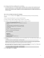
The following steps provide an overview of the installation and configuration procedure for the Dialogic® Diva®
System Release software:
1. Install your Dialogic® Diva® Media Board and connect it to the network. For further information on the
hardware installation, refer to the Dialogic® Diva® Media Board Installation Guide that came with your Diva
Media Board.
2. Install the Diva System Release software package. For further information, see Software installation on
page 16.
3. Configure the Diva System Release software using the Config Configuration Wizard located in the
/usr/lib/opendiva/divas directory. For further information, see Configuring the Dialogic® Diva® System
Release Software on page 22.
4. Confirm the operation of your Diva Media Board. For further information, see Testing the Dialogic®
Diva® Media Board functionality and connectivity on page 33.
5. Configure the Diva System Release software TTY devices. For further information, see Configuring the
Dialogic® Diva® TTY ports on page 35.
15
Software installation
The Dialogic® Diva® System Release software can be installed on a wide range of Linux distributions.
The software consists of an integrated installer, providing automatic detection of the presence and type of the
system package manager:
•
On RPM-based systems, the packages are automatically installed using rpm
•
On Debian-based systems, the packages are automatically converted to a .deb-format and installed using
dpkg
To install the software follow these steps:
1. Ensure that you are logged in as "root" user (or use "su -").
2. Run the following command in a terminal window to start the installation: sh <download
path>/Diva4Linux_installer_<nnn>.bin
•
Where <download path> is the path where you stored the downloaded installer package. and <nnn> is
the software version and build number.
•
Using the command line switch -t <path> you can specify the temporary working directory for the
installer. The default is /tmp/divas.
3. Follow the instructions on the screen. The installer will search for previous versions of the software and
allow uninstallation prior to installing the packaged versions. The configuration files and licenses will be
retained.
4. Move into the source directory where the files have been extracted into: cd /usr/lib/opendiva/divas/src
5. Start the build process: ./Build
16
Files included in the package
The following files are included in the package:
17
•
Device driver for active Dialogic® Diva® Media Boards (divas.[k]o, divadidd.[k]o, diva_idi.[k]o)
•
CAPI 2.0 interface (divacapi.[k]o, kernelcapi.[k]o, capi.[k]o)
•
Dialogic® Diva® TTY (COM port) interface (Divatty.[k]o)
•
The divactrl utility is used to download the protocol code of active Dialogic® Diva® Media Boards, to
configure, and to start Diva Media Boards, to read and translate messages from the board's XLOG interface,
to create a core dump of the board's memory, to control the board via the management interface and to
read and translate messages from the board's MLOG interface (divactrl).
•
Protocol code for Dialogic® Diva® PRI Media Boards and Dialogic® Diva® Multi-PRI Media Boards (*.pm,
*.pm2, *.qpm files and *.bin files)
•
Protocol code for Dialogic® Diva® BRI Media Boards (*.sm, *.sm.4, *.2q0 files, *.bit files and *.bin files)
•
Protocol code for Dialogic® Diva® 4BRI Media Boards (*.qm?, *.2q? files, *.bit files and *.bin files)
•
The tty_test utility allows you to test the TTY interface, to monitor link quality and Dialogic® Diva® Media
Board performance, and to test the hardware (tty_test). This utility uses the TTY interface.
•
ISDN file server, client, and remote management application that uses the ACOPY protocol and allows you to
transfer files, create, remove, or list directories and execute commands on a remote station (acopy2). This
utility uses the CAPI 2.0 interface.
•
A fax application that allows you to transfer and poll fax documents in text and SFF formats with various
transmission speeds and various ECM/compression settings (testfax). This utility uses the CAPI 2.0
interface.
•
Dialogic® Diva® Configuration Wizard detects the hardware and automatically creates the configuration script
(menu driven tools, includes the files Config, Start, Stop, Config.dlg, cfg_util.sh and others). The Diva
Configuration Wizard is started by executing the Config shell script.
•
Shell script used by RPM to create or delete the symbolic links that enable the Dialogic® Diva® System
Release software drivers to be started automatically at system startup (cfg_util.sh) and to enable/disable
the configuration web server.
•
Dummy Dialogic® Diva® configuration file. This file is used to generate warnings if the user forgets to
configure the Diva System Release software after installation (divas_cfg.rc). This file is overwritten by the
Diva Configuration Wizard once the configuration procedure is invoked.
•
Shell script to capture information about your system, hardware, or installation if you have problems to
install, configure, or start the Diva System Release software (Support). This shell script generates a file
named report.txt. You can examine and modify this shell script if it registers information, e.g., phone
numbers that you do not want to pass on to the Dialogic Customer Support. If you change the script, please
send us the modified version together with the report.txt file.
•
Trace shell script that can be used to read driver and Diva Media Board traces for debug purposes.
•
Shell script stops and unloads Dialogic® Diva® drivers (divas_stop.rc).
•
xlog that contains divactrl load -ReadXlog $* and can be used to read XLOG traces from the Diva Media
Board.
•
mlog shell script that contains divactrl mlog $* and can be used to read MLOG traces from the Diva Media
Board.
•
mantool shell script that contains divactrl mantool $* and can be used for management interface access.
•
divaload shell script that contains divactrl load $* and can be used to control the Diva Media Board.
•
divalogd call journal/monitor application. The call journal created by this utility can be used for accounting
purposes and for controlling the quality of service (every call record is stored together with information
about the connection quality).
•
divasnmpx SNMP extension agent providing interface and call statistics. Supports AgentX protocol and trap
generation.
•
Documentation (*.txt and *.html files) extracted to the /usr/doc/packages directory.
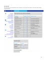
18
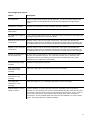
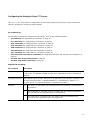
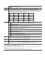
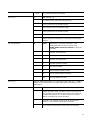
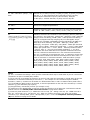
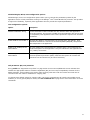
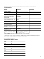
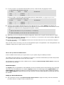
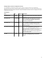
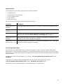
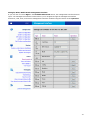
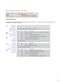
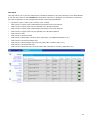
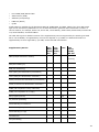
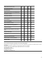
After you have installed your Dialogic® Diva® product, you might need to generate a license and activate it in
the web interface to unlock the required functionality in the product.
You need to generate a license if you have installed one of the following products and purchased a license for
one of the following functionalities:
Product
Functionality
Dialogic® Diva®
System
Release LIN
•
Dialogic® Diva® softIP for SIP v2.2 software
•
Dialogic® Diva® SIPcontrolTM v1.6 software
•
Dialogic® Diva® softSS7 v1.5.2 software
Dialogic® Diva® Media
Boards, except the
Dialogic® Diva® BRI2FX Media Board
G.729 speech compression
•
Data modem support up to V.90
•
AMR-NB voice codec
•
TDM fax support up to V.17
Note: If you have purchased a V.17 fax license, the number of
simultaneous fax calls is limited to half the number of channels the
Dialogic® Diva® Media Board offers. The Diva V-4PRI/E1/T1 Media Board
offers 120/96 channels but enables only 60/48 simultaneous fax calls. The
Diva V-2PRI/E1/T1 Media Board offers 60/48 channels but only 30/24
simultaneous fax calls. Furthermore, the simultaneous fax calls per port are
reduced to half the number of channels the line offers, thus to 15 or 12
V.17 fax calls on one port.
Dialogic® Diva® V-2 or
V-4PRI Media Board
•
TDM fax support up to V.34
Note: V.34 fax is only available if you have purchased 60/48 fax channels
for a Diva V-2PRI/E1/T1 Media Board or 120/96 fax channels for a Diva V4PRI/E1/T1 Media Board and bound the licenses to the Diva Media Board.
Device Unique ID (DUID)
The DUID binds the installed Dialogic® Diva® product to your PC (PC fingerprint).
To get the DUID:
1. Open the Dialogic® Diva® web interface and click License Management.
2. The DUIDs of the installed Diva products are displayed.
3. To use your DUID for the generating a license, select it, right-click it, and select Copy.
4. If you need to do web activation using another computer, open an editor, paste the DUID, and save the file.
See To register your PPC and DUID on page 20 for information about generating a license.
19
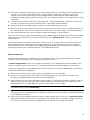
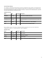
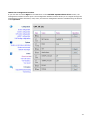
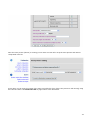
Proof of Purchase Code (PPC)
When you purchase the license, you will receive a PPC either in printed form or via email. By registering this
PPC, you represent and warrant that you lawfully purchased the license.
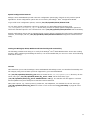
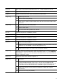
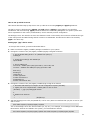
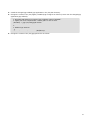
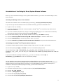
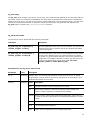
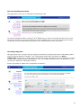
To register your PPC and DUID
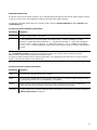
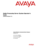
1. Open the following web site: http://www.dialogic.com/activate
2. Enter your PPC and click Check.
20
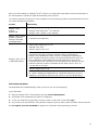
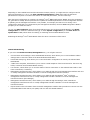
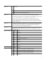
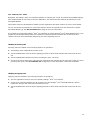
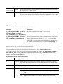
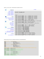
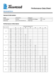
3. If your PPC is valid, the following web site will open:
4. Paste your Device Unique ID (DUID) that you copied from the Diva web interface and enter your email
address to which the license file should be sent.
5. Click Activate to generate the license file that will be sent to the email address you have entered.
6. Save the license file and activate it. For more information, see To activate the license on page 22.
21
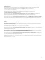
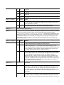
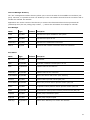
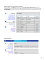
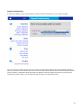
To activate the license
The date set in the system settings of your computer must be correct. Otherwise, you cannot add your license
file.
1. Open the Dialogic® Diva® web interface and click License Management on the lower left side of the
interface.
2. Go to the product for which you want to activate the license and click Browse next to Upload <product>
license file.
3. Go to the directory where you saved the license key file, select it, and click Open.
4. Click Upload to activate the license file.
5. The license file is shown for each product under Installed license files.
Now, the functionality is unlocked for the feature set you acquired with your license.
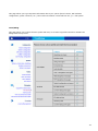
Configuring the Dialogic® Diva® System Release Software
The Config script (located in the /usr/lib/opendiva/divas directory) is a setup wizard that detects the
installed Dialogic® Diva® Media Boards and additional applications.
The setup wizard generates the divas_cfg.rc file (located in the /usr/lib/eicon/divas directory) that is
used to start the Diva Media Boards, interface drivers, and additional software at system startup or to start the
components manually. You can use the script /usr/lib/opendiva/divas/Start to load and
/usr/lib/opendiva/divas/Stop to unload the software manually.
The setup wizard creates the necessary device nodes in the /dev directory:
•
/dev/capi20 is used to access the CAPI 2.0 interface
•
/dev/ttyds01 ... /dev/ttyds<n> is used to access the Dialogic® Diva® TTY interface, where <n> is the sum of
B-channels of the installed Diva Media Boards.
You can either use the Config script or the web-based Dialogic® Diva® Configuration Wizard to configure the
settings for your Diva Media Boards. The following description of configuration options is based on the webbased Diva Configuration Wizard. It is structured as follows:
•
Post installation settings: Steps to be performed immediately after the installation.
•
System and Diva Media Board configuration: Configuration of the major parts of the product that depend on
the type of your application and the switch type that the Diva board is using. Configuration of application
and switch type-dependent parameters that allow you to increase the performance of the system or access
switch-specific services. Configuration of number ranges, peers, protocol-specific settings and startup
options.
•
Control and monitoring: Control Diva Media Board configuration, status and performance data.
•
Maintenance: Initiate trace process, create, view, and download trace files.
22
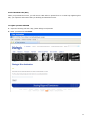
Post installation settings
The Dialogic® Diva® System Release software installs and configures the Dialogic® Diva® WEB Configuration
Wizard (lightweight HTTP server, started via xinetd) that allows you to access and configure the Diva System
Release software via an HTTP browser.
The installation procedure selects a free TCP port number between 10005 ... 10050, modifies your
/etc/services and xinetd configuration files, and restarts the currently active xinetd application.
The installation procedure informs you about the selected port number in the initial "splash" screen that follows
the installation procedure. If you miss this information, which can happen, for example, if you use a graphical
RPM manager, you can obtain this information with the command: grep "diva-cfg" /etc/services.
If you do not want to use the Dialogic® Diva® WEB Configuration Wizard, you can disable it with the command:
cd /usr/lib/opendiva/divas && sh cfg_util.sh 4. To re-activate the Diva WEB Configuration Wizard, use
the command cd /usr/lib/opendiva/divas && sh cfg_util.sh 3.
To access the Diva WEB Configuration Wizard you need to edit the
/usr/lib/opendiva/divas/httpd/login/login file and configure your password.
Note that the "login2 file must meet the following requirements, otherwise the password will be ignored:
•
The file must be owned by root.
•
Permissions must be 600 or 400.
•
The password must be located in the first line of the file, contain printable characters only and consist of not
less than 7 characters.
System and Dialogic® Diva® Media Board configuration
The system and Diva Media Board configuration is divided in two parts:
•
System configuration on page 23 to configure the type of application, the system startup mode, and
global parameters.
•
Board configuration on page 24 to configure parameters of the installed Diva Media Boards in accordance
with the information required by the service provider or the PBX to which the Diva Media Board is
connected.
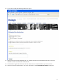
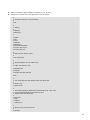
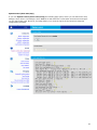
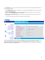
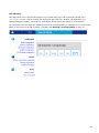
System configuration
Online help is available for any system configuration option. To open the online help for a specific parameter,
click the parameter and a window with the help text pops up.
1. In the system configuration, select the applications and activate the interfaces that meet your requirements.
For example, if you want to set up a fax polling server that is based on the TTY interface, select "TTY
interface" and "fax/voice support for TTY".
2. Depending on the selected application scenario, you can set FAX CLASS 2 options like ECM, compression,
etc. For further information, see the online help or Intelligent FAX CLASS 2 processing on page 54.
23
3. The system configuration also allows you to specify startup options for your Dialogic® Diva® Media Boards. If
you plan to clone your system configuration on other computers, disable the verification of the serial
numbers. If you want to view debug or trace messages that are issued during the Diva Media Board
configuration, enable "Debug code for microcode load". For further information on these parameters, see the
online help.
4. To write detailed call log records to the /var/log/divalog.../var/log/divalog.N file, activate the "call history".
The call log records can be used for accounting and for generating different statistics.
5. Specify if the divasnmpx SNMP extension agent should be started during driver load.
6. Specify if the driver load should be forced even if the driver's kernel version does not completely match your
Linux kernel version. Note that you cannot force a driver load if your Linux system uses kernel checksums.
7. Specify if the Dialogic® Diva® drivers should be loaded automatically on system startup.
At the end of the system configuration, the Dialogic® Diva® WEB Configuration Wizard will prompt you to restart
the Diva drivers if necessary.[2] To restart the Diva drivers, go to System control, where you can stop and
start the drivers.
Some of the changes, for example, "Start driver on system boot" or "Debug mode for microcode load" do not
affect the state of the currently running drivers and change only the driver behavior at system or Dialogic®
Diva® Media Board start. The Dialogic® Diva® WEB Configuration Wizard ignores changes of these parameters
and does not prompt you to restart the Dialogic® Diva® Media Board drivers.
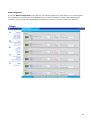
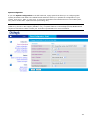
Board configuration
Context-specific online help is available for most configuration options. To open the online help for a specific
parameter, click the parameter and a window with the help text pops up.
The Board configuration allows you to configure the Dialogic® Diva® Media Boards that are installed in your
system as required by your service provider or by the PBX to which the Diva Media Boards are connected.
To start the configuration of a Diva Media Board, select its "board" icon in the Diva Media Board list. The basic
configuration parameters are displayed.
1. Specify the D-channel protocol (switch type) as provided by your service provider.
2. Specify if you want to operate your board as terminal equipment (TE) or as network termination (NT).
Normally, Diva Media Boards are operated as terminal equipment.
3. Specify whether you are using a direct dial in (DDI) interface. A direct dial in interface provides you with an
ISDN line with a basic phone number that is able to accept any extension digits and to pass them to the
ISDN applications. If you select Yes, also specify the direct dial in number length.
Note: This option is not available for D-channel protocols. A better control of incoming called party numbers
is available using the option Call Routing.
4. Specify the layer 1 framing type. The National default setting automatically sets the correct layer 1
framing type for the selected switch type. Change this setting only if you are using your Diva Media Board in
a non-standard environment.
5. Specify the voice companding type that is used to transmit analog data on your line. The National default
setting automatically sets the correct voice coding for the selected switch. You need to change this setting
only if the voice coding required by your PBX does not correspond to the coding of the switch.
24
Depending on the installed board and the selected D-channel protocol, you might need to configure various
advanced parameters. To do so, set View extended configuration to Yes and modify the advanced
parameters as required. For further information on advanced parameters, see the online help.
After the board configuration is complete, the Dialogic® Diva® WEB Configuration Wizard stores the parameters
list, generates a startup shell script and tries to update the modified parameters via the management interface.
If updating via the management interface is not possible, for example, the board is not running or the
configuration parameter is not supported by the management interface, the Diva WEB Configuration Wizard
prompts you to restart the board.
You can use Start hardware option from the dropdown menu next to the Diva Media Board in the Board
configuration to restart the selected board [3] or under System configuration you set Start driver on
system boot to Yes, which allows for starting or restarting the Diva Media Boards at once.
Restarting the Dialogic® Diva® Media Board clears the active connections of this board.
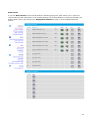
Control and Monitoring
If you select the Hardware status/management icon, you will gain access to:
•
Current status of the Dialogic® Diva® Media Board hardware, which allows you to view hardware-related
settings and to control the state of the Diva Media Board hardware.
•
Diva board startup log, which allows you to view the board's configuration as seen by the selected Diva
Media Board.
•
"XLOG" trace snapshot, which allows you to receive a small snapshot of the board traces for the trace ring
buffer, located in the Diva Media Board memory.
•
Line monitor, which allows you to view the status of active connections on the selected board and to clear
these connections, if necessary.
•
Management interface browser, which allows you to walk through the board management interface and view
or modify management interface variables or execute management interface functions.
•
Management interface browser, which allows you to walk through the Dialogic® Diva® TTY driver
management interface and view or modify management interface variables or execute management
interface functions (Port Manager).
•
Management interface browser, which allows you to walk through the Dialogic® Diva® CAPI driver
management interface and view or modify management interface variables or execute management
interface functions.
•
Report based on the information from the board management interface that provides an overview over the
Diva Media Board's link status, link quality and over the call-related statistics.
25
Maintenance
The Dialogic® Diva® WEB Configuration Wizard provides access to the following maintenance functions:
•
System environment on page 26 allows for viewing hardware-related settings of the host system.
•
Trace/Debug on page 27 allows for creating debug and trace files of the Dialogic® Diva® Media Board or
the system.
•
Support/Troubleshooting on page 27 allows for capturing information required for the support request in
case of installation problems.
•
System messages on page 27 allows for viewing the latest system messages (dmesg).
•
View trace file on page 28 allows for decoding, viewing, and filtering debug and trace files.
•
View call history on page 28 allows for viewing the latest call history file.
•
View statistics on page 28 allows for generating and viewing statistics, based on the call history files.
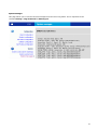
System environment
The system environment browser allows for viewing information about:
•
Kernel version
•
CPU(s)
•
PCI bus configuration
•
I/O memory configuration
•
I/O port configuration
•
DMA configuration
•
Interrupt configuration
•
APM configuration
•
Loaded modules
•
Installed devices
•
Memory usage
26
Trace/Debug
The Dialogic® Diva® Trace Wizard allows for selecting various trace profiles and thus enables you to trace
everything or to suppress unnecessary information in certain scenarios. Detailed information on the various
trace profiles is given in the online help. To display the online help for a profile, click its name.
The Diva Trace Wizard also allows you to set the size of the trace ring buffer - a binary file where the trace
information is stored - and to start the trace process in the background.
After the trace process is started, you can leave the Diva Trace Wizard or close your HTML browser without
affecting the running trace process.
While the trace process is running (and after the trace process is stopped), you can decode, filter, and view the
content of the trace ring buffer file with the trace file browser (View trace file).
To stop a running trace process, enter the Diva Trace Wizard again; the Diva Trace Wizard will remember that
the trace process is still running, and stop it. After stopping the trace process, you can download the
compressed binary trace file.
Support/Troubleshooting
If you should experience any problems after the installation of the Dialogic® Diva® System Release software, for
example, no Dialogic® Diva® Media Boards can be detected, use the Dialogic® Diva® Support Wizard to capture
and download in compressed form the information that is required to process your support request. Select one
of the following options:
•
Capture the necessary information about your system (kernel version, PCI-bus configuration, system
configuration files).
•
Capture the necessary information about your system (kernel version, PCI-bus configuration, system
configuration files) and a binary image of the installed kernel and related modules. With this option, the
Dialogic Customer Support can reproduce your environment if this should be necessary to process your
support request. Select this option only if requested by the Dialogic Customer Support.
System messages
The system log viewer allows you to view the latest kernel messages. You can use this information to control
the load and operation of Dialogic® Diva® drivers and to check your system for unexpected errors, driver
failures, or exceptions ("Oops").
27
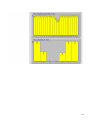
View trace file
The trace file browser allows for decoding, filtering, and browsing the trace file without downloading this file to
your machine and without stopping the trace process.
The trace file viewer displays a list of the Dialogic® Diva® debug and trace sources information contained in the
trace file and it allows you to select the sources of information that you want to view, decode, and display.
The trace viewer highlights messages in the trace information window by the following colors:
•
Yellow - highlights messages related to initial call establishment
•
Green - highlights messages related to the call establishment progress and completion
•
Red - highlights messages related to the call disconnect procedure
To get detailed decoded information on trace and debug messages, click the "highlighted" links in the trace
information window.
View call history
The call history (call journal/log) is stored as a sequence of files named divalog,divalog.1...divalog.N, where
N is the integer number in the /var/log directory. The divalog.N file contains the oldest trace information
while the divalog file contains the latest (current) information about the call activities.
You can use the call history viewer to decode the divalog file (call time, duration, type, speed) and view this
information without downloading the call history file to your local machine.
To download call history files, click Download. You will receive a text file that displays the various components
of the call history information separated by commas. The first line of the file contains the description of the
components.
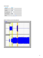
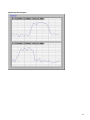
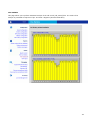
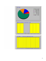
View statistics
The Dialogic® Diva® Statistics Viewer analyzes the call history files found in the /var/log directory and creates
various statistics based on these files. The statistics show the total number of calls related to various periods of
time, the ratio of incoming and outgoing calls, the ratio of call types, call duration charts, a peak board load
chart, etc.
The statistic information is presented in a graphical format (jpeg) and can be used to analyze the system load
and reliability.
If you want to create your own statistics, download the call history files in the call history viewer and apply your
own spread-sheet application.
28
Loading the Dialogic® Diva® modules
During installation and configuration, the divas_cfg.rc script is automatically generated. This script is used to
load protocol, CAPI, and TTY interfaces. On system startup, the Dialogic® Diva® Media Boards will be started by
symbolic links named S03DIVAS4LINUX and S06DIVAS4LINUX_NETWORK. These links are created as part of the
installation process and are located in the runlevels 2, 3, and 5 of the following directories (system and version
dependent): /etc/rc.d/ directories for Red Hat, in the /sbin/init.d/ or /etc/init.d/ directories for SuSE
and in the /etc/rcX.d/ directories for Debian and others.
•
If you wish to remove these links, execute: sh /usr/lib/opendiva/divas/cfg_util.sh 2. If you wish to
restore these links, execute: sh /usr/lib/opendiva/divas/cfg_util.sh 1).
•
If you have changed the configuration or wish to restart or stop the Diva Media Boards without restarting
your system, you can use the /usr/lib/opendiva/divas/Stop script to stop the Diva Media Board and
unload the Dialogic® Diva® drivers.
•
You can run the /usr/lib/opendiva/divas/Start script to load the Diva drivers and start the Diva Media
Boards.
•
If you wish to restart only one specific Diva Media Board, you can do so without unloading the drivers by
executing the /usr/lib/opendiva/divas/divas_cfg.rc restart <x> command, where <x> is the logical
board number.
•
If boards support multiple interfaces (e.g., 4BRI), the board number should be the number of the master
board. After the board was stopped, you can load and start it again without affecting other boards.
•
If boards support multiple interfaces, the logical boards that belong to the same physical board are affected.
•
An updated configuration can be written to the drivers by executing the
/usr/lib/opendiva/divas/divas_cfg.rc restart -1 command.
Dialogic® Diva® Media Board information
To interpret the Diva Media Board, driver, and trace data the following information is necessary:
•
Physical and logical Dialogic® Diva® Media Board number on page 29
•
"/proc" file system on page 30
Physical and logical Dialogic® Diva® Media Board number
Every Dialogic® Diva® Media Board that is installed in the system is a "physical" board. Every physical board
contains one or more ISDN or analog interfaces. Each interface is represented in the system by a "logical"
board. Example: Three physical Diva Media Boards are installed in the system: a Dialogic® Diva® BRI Media
Board, a Dialogic® Diva® PRI Media Board, and a Dialogic® Diva® 4BRI Media Board. The Diva BRI Media Board
and the Diva PRI Media Board add one logical board each. The Diva 4BRI Media Boards adds four logical boards
to the system. If one physical board contains multiple logical boards, a continuous block of board numbers is
allocated to these boards. The first logical Diva Media Board is the "master" board. This board is responsible for
the hardware resources of the physical board and for loading, starting, and stopping the logical boards provided
by the physical board. In the other aspects (functionality, configuration, selected protocol, debug buffers, and
features) the logical boards are independent from the location of their physical boards: on different physical
boards or on the same physical board.
29
"/proc" file system
After being started, the DIDD (divadidd.[k]o) driver creates the directory /proc/net/isdn/eicon for kernel 2.4.x
and the directory /proc/net/eicon for kernel 2.5.x and higher in the proc file system. You can read the file
divadidd in this directory (for example by executing cat divadidd) to get version information on the DIDD
driver.
After being started, the XDI driver (divas.[k]o) creates the file divas in the /proc/net/[isdn/]eicon directory.
You can read this file (for example by executing cat divas) to get version information on the XDI driver. A
subdirectory named adapter<no> (<no> is the logical Dialogic® Diva® Media Board number) is created in the
directory /proc/net/[isdn/]eicon for every logical Diva Media Board present in the system.
Each adapter<no> directory contains the following files:
info
You can read this file (cat info) to get information on the Diva Media Board: board name,
serial number, number of channels supported by the board, hardware resources assigned to
the board, board state. Possible board states are: ready (ready to download and start
firmware or fpga), active (operating), trapped (firmware problem, core dump should be
generated), unknown (hardware problem), and slave (slave board of a Diva Media Board
that supports multiple logical boards)
group_optimization You can read this file (cat group_optimization) to get the current state of this feature
(on|off - 1|0). You can write "1" to this file to turn this feature on (echo 1 >
group_optimization). You can write "0" to this file to turn this feature off (echo 0 >
group_optimization). For further information on this feature, see the online help.
dynamic_l1_down
You can read this file (cat dynamic_l1_down) to get the current state of this feature
(on|off - 1|0). You can write "1" to this file to turn this feature on (echo 1 >
dynamic_l1_down). You can write "0" to this file to turn this feature off (echo 0 >
dynamic_l1_down) for further information on this feature, see the online help.
30
Global fax configuration options
Global fax configuration options allow for overwriting parameters passed by the fax application to the Dialogic®
Diva® Media Board and to control parameters running on the Diva Media Board's T.30 protocols. This provides a
high level of flexibility, especially if the fax application does not provide the required parameters.
31
Fax configuration options
Option
Description
Fax speed limit
Allows to limit the transmission speed. Normally, you do not need to limit the fax
speed because the Diva Media Board automatically negotiates the appropriate
speed.
Disable fine resolution
Disables the transmission of fax messages with high resolution.
Disable Error Correction
Mode (ECM)
Disables the transmission of fax messages using ECM (Error Correction Mode).
Use ECM frame length of
64 bytes
Forces usage of HDLC frames with a maximum length of 64 bytes if transmitting fax
messages using ECM (Error Correction Mode).
Disable 2D fax document
compression
Disables usage of 2D fax document compression. This option also disables the
automatic (transparent to application) fax document compression provided by the
Diva Media Board in order to increase the effective transfer speed of fax messages.
Disable T.6 fax document
compression
Disables usage of T.6 fax document compression. This option also disables the
automatic (transparent to application) fax document compression provided by the
Diva Media Board in order to increase the effective transfer speed of fax messages.
Disable uncompressed T.6 In some cases, compression of a fax document line results in a line that is longer
fax document lines
than the uncompressed original. The T.6 protocol allows you to reduce the fax
transmission time by transmitting such lines without compression. This option
disables the line compression optimization.
Refuse incoming polling
requests
Disables incoming polling requests.
Hide "total pages"
information in fax
message
Hides the "total pages" information field in the fax message.
Hide "head line"
information in fax
message
Hides the "headline" information field in the fax messages.
Hide "page info"
information in fax
message
Hides the "page info" (i.e. message head) field in the fax messages.
Disable fallback to lower
speed on failure
"Feature fallback" is used to prevent excessive resending of fax documents if
working over poor quality lines. The Diva Media Board internally saves the fax ID of
the last peer and the results of the fax transmission from this peer. If the results of
the last fax transmission were negative and the application starts message retransmission, the Diva Media Board will detect this and fallback to a lower transfer
speed. This setting allows for disabling fallback.
32
Special configuration features
Dialogic® Diva® Media Boards provide numerous configuration options part of which are only used in special
applications. These configuration options are not covered by the Dialogic® Diva® Configuration Wizard.
To get a full list of configuration options, execute /usr/lib/opendiv/divas/divactrl load.
You can apply special configuration options by modifying your Diva Media Board's startup script
/usr/lib/opendiva/divas/divas_cfg.rc. In this case, you have to specify special configuration options as
well as the standard options in the command line of the /usr/lib/opendiva/divas/divactrl board load utility.
Special configuration options can be changed during run time without restarting the board via the management
interface, for example, with the /usr/lib/opendiva/divas/divactrl mantool management interface access
utility.
Testing the Dialogic® Diva® Media Board functionality and connectivity
The following procedures will help you to verify if the Dialogic® Diva® Media Board and the service are working
properly. After configuring and loading the drivers, it is recommended that you use one or more of the following
methods for testing.
TTY test
This test allows you to test the Dialogic® Diva® Media Board and Dialogic® Diva® TTY interface functionality and
link integrity using various bearer protocols supported by your Diva Media Board.
The /usr/lib/opendiva/divas/tty_test utility is located in the /usr/lib/opendiva/divas directory. On the
server side, type: /usr/lib/opendiva/divas/tty_test 1 s auto. On the client side, type:
/usr/lib/opendiva/divas/tty_test 2 <ISDNnumber> x75 [4]. The transfer rate will appear in real time
and be updated every time 64 Kbytes of data have been transferred.
Many other options, e.g., bearer protocol, packet size, rate adaptation, are available for the TTY test. Type
/usr/lib/opendiva/divas/tty_test for a full list or refer to the section tty_test utility on page 95 in this
document.
33
ACOPY2 file server
This tool allows you to test the Dialogic® Diva® Media Board and CAPI 2.0 interface functionality and link
integrity using the X.75/T.70NL bearer protocol. The acopy2 [5] utility is located in the
/usr/lib/opendiva/divas directory.
Many other options, e.g., packet size, CPN, SubAddress, and commands are available. Type
/usr/lib/opendiva/divas/acopy2 for a full list.
On the server side, type: /usr/lib/opendiva/divas/acopy2 -c<X> -serve /p2048, where 2048 is the
packet size for beneficial results and <X> is the CAPI board number that will receive the call.
On the client side, type: /usr/lib/opendiva/divas/acopy2 -c<Y> - n<ISDNnumber>:file2 file1 /p2048,
where 2048 is the packet size for beneficial results and <Y> is the CAPI board number that will issue the call.
Testfax
This tool allows you to test Dialogic® Diva® Media Board and CAPI 2.0 interface functionality and link integrity
using the Fax G3 bearer protocol.
The TESTFAX utility is located in the /usr/lib/opendiva/divas directory.
On the server side, type: /usr/lib/opendiva/divas/testfax -serve -c<X> [6], where <X> is the CAPI board
number that will receive the call.
Many other options, e.g., packet size, transmission speed, ECM, SEP/SUB/PWD, compression, fax ID, headline,
and commands are available. Call /usr/lib/opendiva/divas/testfax for a full list.
On the client side, type: /usr/lib/opendiva/divas/testfax file.sff|file.txt <ISDNnumber> -c<Y>, where
<Y> is the CAPI board number that will issue the call.
TESTFAX will transmit the file.txt text file or the file.sff SFF file as fax document. The received document
will be saved in the rcv.sff file.
34
Configuring the Dialogic® Diva® TTY ports
The /dev/ttydsxx ports must be configured by AT commands (parameters enclosed in square brackets are
optional. Variables are enclosed in angle brackets).
AT-command set
The following commands are supported by the Dialogic® Diva® System Release software:
•
AT commands see "Supported AT commands" on page 35
•
AT\ commands see "Supported AT\ commands" on page 39
•
AT% commands see "Supported AT% commands" on page 40
•
AT# commands see "Supported AT# commands" on page 41
•
AT& commands see "Supported AT& commands" on page 41
•
AT$ commands see "Supported AT$ commands" on page 43
•
AT+ commands see "Supported AT+ commands" on page 43
•
Class Fax1 and class Fax2 AT commands see "Supported Class Fax1 and class Fax2 AT commands" on
page 49
•
AT+FTD. Set current time and date on page 50
•
AT+FPH. Page header generation on page 50
Supported AT commands
AT command
Description
AT A
ANSWER. Accepts an incoming call that has been indicated by a "RING". If the S0 register
is set to zero, TTY indicates a RING until the call is answered by the AT A command or
released.
AT D[T|P]<number>
DIAL. Dials the given number. Dial tone (T) or dial pulse (P) are ignored. <number> can
have the following format: <CalledPartyNumber>[| <Subaddress>][^56k][+i<y> |
+p=btx] where <y> is the Diva-specific +I command (see below).
AT E[0|1]
<n> Echo mode. In echo mode, the commands sent to the modem are echoed back to
the terminal.
0
Echo mode OFF. In command mode, the modem does not reflect the data that it
has received from the application back to the application.
1
Echo mode ON. In command mode, the modem reflects the data that it has
received from the application back to the application.
35
AT I[<n>]
INFO. Returns the modem identification string. <n> : integer ranging from 0 to 9
AT H[0]
HANGUP. Disconnects the line.
AT O[1]
ONLINE. Switches the modem from command mode to data mode.
AT Q[<n>]
<n> Modem response mode
AT V[<n>]
0
Returns result codes (default)
1
Quiet mode. In quiet mode the modem driver does not return result codes for the
commands.
<n> Modem response (result code) format
0
Numeric result codes.
1
Plain text result codes (verbal mode, default).
AT L<n>
Command accepted for compatibility reasons.
AT N<n>
Command accepted for compatibility reasons.
AT M<n>
Command accepted for compatibility reasons.
AT Y<n>
Command accepted for compatibility reasons.
AT X<n>
<n> Result code reporting option
0
Enables minimum information only (plain CONNECT in case of successful connection
establishment, NO CARRIER in case of dialing/answer error).
4
Enables full information (the result codes are reported, default).
AT Z[<n>]
Soft reset. Drops the connection if the modem is in ESCAPE mode. Resets the modem
and restores the selected predefined modem configuration profile <n>. See Supported
TTY profiles on page 52 for more information. See AT&F below for the list of predefined
modem configuration profiles.
AT S<r>=?
Displays the value of the selected S-register <r>.
AT S0=<n>
<n> Description
0
Disables auto answer. Incoming calls are answered with an ALERT message and
indicated by RING messages (every 4 sec). The user can investigate the call
parameters, select the appropriate profile or settings and accept the call by the AT
A command. The user can issue the AT H command to reject the incoming call.
1 ... Enables auto answer. Incoming calls are indicated by a RING and accepted
254 automatically.
255
Ignores the incoming calls (default).
36
ATS2=<n>
ATS7=<n>
<n> Description
(0
...
255)
127
Disables the escape sequence process, i.e. no escape character is recognized.
43
The default value of the ESCAPE character ("+").
Default value is set to zero (e.g., modem will use protocol-specific default value).
Modem mode: time to wait for carrier. Sets the time in seconds that the modem will wait
for a carrier before hanging up. <n> is a range from 0 to 255 seconds.
Fax mode: time to wait for connect. Sets the time in seconds that fax will wait for
connection before hanging up. Suggested value is 200 seconds. Values less than 10
seconds are ignored. The carrier waiting time starts after the connection was established
and is set to 60 seconds.
ATS9=<n>
Carrier Detect Response Time. Sets the time in tenths of a second that a carrier must be
present before the modem considers it valid. <n> is a range from 0 to 255 tenths of a
second. This register is only implemented for compatibility reasons. Writing to this
register does not affect the Carrier Detect Response time.
ATS10=<n>
Delay between carrier loss and hang up. Sets the time in tenths of a second that the
modem waits before hanging up after a loss of carrier. <n> is a range from 0 ... 255
tenths of a second.
ATS27=<bitmask>
Bit
Value
Result
0
1
Reserved
1
2
Reserved
2
4
Reserved
3
8
Disables 2100 Hz answer tone
4
16
Reserved
5
32
Reserved
6
64
Reserved
7
128
Reserved
Bit
Value
Result
0
1
Disables error correction for 1200 bps connections
1
2
Disables error correction for V.22bis connections
2
4
Disables error correction for V.32bis connections
3
8
Reserved
ATS51=<bitmask>
37
ATS91=<bitmask>
4
16
Reserved
5
32
Reserved
6
64
Reserved
7
128
Reserved
Bit
Value
Result
0
1
Use reverse SDLC establishment (SNRM sent by answerer and not by
caller). Mandatory for POS.
1
2
Poll on each SDLC frame. Required by some POS terminals.
ATS92=<n>
SDLC Address A (default 0x30)
ATS128
S-register 128 is a read-only register. Reading this register allows to retrieve information
on the current (last) incoming call. It returns a message in the following format:
;<calling party number>;<destination_address>. If calling party or destination subaddresses are present, they are separated by a slash "/" from the called party number or
the destination address. For example, the calling party number 800, calling party subaddress 900, destination address 400, destination sub-address 500 are presented as:
;800/900;400/500.
ATS172=<bitmask>
Bit
Value
Result
0
1
Enable transmission and reception of empty frames.
1
2
Enable "multimoding", i.e. a trailing byte (modulation tag) in every
frame specifies which modulation has to be used to send this frame or at
which modulation it was received. Valid modulation tags are 0x27 for
V.23 HDX off hook and 0x28 for V.23 HDX on hook.
2
4
Shield empty frames. This mode enables a tty application to send and
receive empty frames. Since a frame with a length of 1 byte is invalid in
the V.23 SMS and V.23 Caller ID protocol, it is used to carry the
information that an empty frame occurred and which modulation was
detected. The data byte in a real 1 byte frame is replaced by a unique
value 0xff. A single byte frame 0x27 indicates or issues an empty frame
in V.23 HDX off hook. A single byte frame 0x28 indicates or issues an
empty frame in V.23 HDX on hook.
ATS253=<n>
<n> (0 ...
127)
Description
Set
Write allows to set coded in accordance with Q.931 cause value to be
used to disconnect this call (for example by ATH/ATZ commands or by
DTR drop operation). The Dialogic® Diva® Media Board provides
conversion between used national dependent values/in band procedures
and Q.931.
Read
Read after disconnect provides coded in accordance with Q.931 value of
disconnect cause. The Dialogic® Diva® Media Board provides conversion
between used national dependent values/in band procedures and Q.931.
38
ATS254=<bitmask>
Bit
Value
Result
0
1
Allows to reject incoming call using ATH, ATZ commands or using DTR
drop procedure.
1
2
Activate TIES (Time Independent Escape Sequence). The TIES procedure
switches to command mode if "+++AT<CR>" (where <CR> represents
hex digit 0x0D) sequence is detected in the data stream after a 20 ms
pause and is followed by a 40 ms pause.
ATS1001=<number> Second origination address. This number is placed as the second origination address.
ATS1002=<number> Specifies the numbering plan identifier for the second origination address. Number should
be in the range 0...255. If number is set to 128 or larger then octet 3a (presentation and
screening indicator) is not used.
ATS1003=<number> Specifies the presentation (bits [7:6] in octet 3a of origination address) and screening
(bits [2:1] in octet 3a of origination address) for the second origination address. Number
should be in the range 0...127.
Supported AT\ commands
AT
command
Description
AT \V[<n>]
<n> CONNECT message format
0
Plain CONNECT message without any connection parameters.
1
Full CONNECT message including connection parameters (modulation, compression,
transmit/receive rate).
2
Full CONNECT message in multi-line format: CONNECT, TX/RX, CARRIER, PROTOCOL,
COMPRESSION.
AT
Inactivity timeout (s). TTY releases the connection if there was no data traffic on the interface for
\T[0...65535] the time interval specified here.
AT \D[<n>]
Debug level. Reserved for use by Dialogic Corporation.
AT \N[<n>]
<n> Error correction control
0|1
Turn off error correction, error correction detection, and data compression (i.e. connect in
transparent mode only).
2
Disable V.42 error correction and V.42 error correction detection (i.e. MNP only). In case of
failure, connect in transparent mode.
3
Try to establish error correction; try to detect error correction (any supported). In case of
failure, connect in transparent mode.
4
Force V.42 error correction. Disconnect in case of failure.
39
5
Force MNP error correction. Disconnect in case of failure.
6
Force V.42 or MNP error correction. Disconnect in case of failure.
7
Try to establish V.42 error correction; try to detect V.42 error correction. In case of failure,
connect in transparent mode.
8
Try to establish MNP error correction; try to detect MNP error correction. In case of failure,
connect in transparent mode.
10
Force SDLC error correction. Disconnect in case of failure.
11
Try to establish SDLC error correction. In case of failure, connect in transparent mode.
12
Try to establish SDLC or MNP error correction. In case of failure, connect in transparent
mode.
13
Try to establish SDLC or V.42 error correction. In case of failure, connect in transparent
mode.
14
Try to establish SDLC or V.42/MNP error correction. In case of failure, connect in
transparent mode.
Supported AT% commands
AT
command
Description
AT
%C[<n>]
<n>
Data compression control
0
Turn data compression off
1
Turn data compression on
40
Supported AT# commands
AT
command
Description
AT #CID=?
Displays CID (Caller ID) setting. The short form of this command is "CID?".
AT
#CID=<n>
<n> Sets CID mode. The TTY indicates the origination (CID) and destination (DAD) number in the
RING and/or CONNECT message. This enables a server application for example to forward
incoming calls directly to their destination. [a]
0
No CID indication
1
CID indication in RING message [a]
2
CID indication in CONNECT message [b]
3
CID indication in RING and in CONNECT messages
5
CID and DAD (Destination Address [a]) indication in RING message [c]
6
CID and DAD [a] indication in CONNECT message [d]
7
CID and DAD [a] indication in RING and in CONNECT messages
9
Use an mgetty friendly format for CID indication in RING message [e]
15
Use an mgetty friendly format for CID and DAD [a] indication in RING message [f]
Notes:
[a] CID (Calling Party Number) is indicated as: RING CID: <number>
[b] CID (Calling Party Number) is indicated as: CONNECT ... CID: <number>
[c] Indicated as: RING CID: <number> DAD: <number>
[d] Indicated as: CONNECT ... CID: <number> DAD: <number>
[e] Indicated as: RING;<number>
[f] Indicated as: RING;<number>;<number>
Supported AT& commands
AT
command
Description
AT &C[<n>] Accepted for compatibility reasons. <n> : any integer
AT &G[<n>] <n>
Guard tone options
0
Turns guard tone off (default).
1
Turns 550 Hz guard tone on.
41
2
Turns 1800 Hz guard tone on.
AT &D[<n>] Data Terminal Ready (DTR) options. <n> ranges from 0 to 3. See AT&Q command below.
AT &Q[<n>] Communication options. <n> ranges from 0 to 3. Data Terminal Ready (DTR) options and
Communication (COM) options determine the behavior of the virtual modem when DTR switches
from ON to OFF in accordance with the following table:
AT &K<n>
&Q
&D0
&D1
&D2
&D3
&Q0
N [a]
B
C
D
&Q1
A [b]
B [c]
C [d]
D [e]
&Q2
C
C
C
D
&Q3
C
C
C
D
<n>
Terminal flow control options. Defines the flow control mechanism.
0
Disables flow control.
1
Enables RTS/CTS local + remote flow control (obsolete).
2
Enables XON/XOFF flow control (obsolete).
3
Enables RTS/CTS local + remote flow control.
4
Enables XON/XOFF flow control.
5
Enables transparent XON/XOFF flow control.
6
Enables both XON/XOFF and RTS/CTS flow control (voice).
AT &V
Displays the current configuration, the last number that has been dialed (last DIAL to), and the
calling party number of the last incoming call (last RING from).
AT &V1
Displays current settings and settings of the available profiles.
AT &F[<n>] Resets the modem and restores the selected predefined modem configuration profile. AT&F sets
factory defaults for current profile. See Supported TTY profiles on page 52 for details.
Notes:
[a] No action is taken, the DTR drop is ignored.
[b] If the modem is online, it hangs up and responds with OK.
[c] If the modem is online, it switches to command mode (as if an ESCAPE sequence was detected) and sends
OK.
[d] If the modem is online, it hangs up and responds with OK.
[e] If the modem is online, it hangs up and the current profile defaults are restored.
42
Supported AT$ commands
AT command
Description
AT $F<number>
Controls Dialogic® Diva® FastSetup. 0 - Normal connection (default), 1 - FastSetup
without answer/calling tone, 3 - FastSetup with answer tone. The AT+MS command can
be used to control the allowed FastSetup modulations: AT+MS=V90a,1 - v.22 and
v.22bis FastSetup, AT+MS=v22 - v.22 FastSetup, AT+MS=v22b,0 - v.22bis FastSetup.
Supported AT+ commands
AT command [a] [b]
Description
AT +iA<number>
Accepted address. Incoming calls are only accepted if the called party
number equals the phone number configured here. Addresses are
compared backwards. So, if you set the accepted address to 12, the called
party numbers that end with 12, e.g., 12, 812, 384012, match the
configured address. [c]
AT +iO<number>
Origination address. This number is placed as the origination address. [c]
AT +iB<n>
<n>
B-channel data adaptation rate [d]
2
1200 bps
3
2400 bps
4
4800 bps
5
9600 bps
6
19200 bps
7
38400 bps
8
48000 bps
9
56000 bps
<n>
Determines whether the modem stays in command mode
after call setup.
0
Stays in command mode.
1
Switches to data mode.
<n>
Delay for AT-command response (ms).
0
AT-command response is sent immediately.
AT +iC[<n>]
AT +iD<n>
43
AT +iF<n>
AT +iG<bitmask>
1 ... 255
AT-command response is delayed.
<n>
RNA Framing. [e]
0
No framing check (pass data transparently).
1
Force synchronous conversation (PPP).
2
Force asynchronous conversation (PPP).
3
Force synchronous conversation (RAS).
4
Force asynchronous conversation (RAS).
5
Detects required conversation by analyzing incoming data
packets.
Bit
Value
RNA patches. Controls the behavior of the
ASYNC/SYNC PPP conversion module. See
ASYNC/SYNC conversion module on page 54
for details.
1
1
Reserved, should be zero.
2
2
Reserved, should be zero.
3
4
Reserved, should be zero.
4
8
Pass IPCP (default is track).
5
16
Force patch of IPCP.
6
32
Keep RX ACCM (default is add).
7
64
Keep TX ACCM (default is delete).
8
128
Pass LCP (default is track).
AT +iL<n>
Maximum data frame length. <n> should be in the range of 0 ... 2048. 0
defaults to the maximum frame length supported by the Dialogic® Diva®
Media Board.
AT +iM<n>
<n>
Working mode
1
Normal operation mode. TTY does not try to preserve the
protocol data unit boundaries (streaming). This mode fully
emulates the behavior of a "classic" modem or terminal
adapter connected via a serial interface.
2
Fax mode. TTY switches to this mode as soon as a Fax
CLASS 1 or Fax CLASS 2 command is detected.
3
Voice mode (bit-transparent access to B-channel data).
44
AT +iN<Format>
AT +iP<n>
4
RNA mode. TTY operates in framing mode, investigates
protocol data units, and provides ASYNC/SYNC conversion if
necessary.
5
BTX over ISDN mode.
6
Frame mode. The TTY preserves the frame boundaries of the
ISDN data frames. Note that the Linux TTY interface will
stream the data again.
Format
Numbering plan for destination/origination address and
presentation/screening indicators for origination address.
Number1[/N
umber2[/Nu
mber3[/Nu
mber4]]]
Specifies the numbering plan identifier for the destination
address (Number1), origination address (Number2),
presentation indicator - bits [7:6] in octet 3a of origination
address (Number3) and screening indicator - bits [2:1] in
octet 3a of origination address (Number4). Number1 and
Number2 should be in the range 0...127. Number3 and
Number4 should be in the range 0...3.
<n>
Specifies the protocol stack used to transfer bearer data.
1
L1 - HDLC, L2 - X.75SLP and V.42bis data compression
autodetection in case of incoming connection, L3 transparent
2
L1 - V.110 synchronous mode, L2 and L3 - transparent
3
L1 - V.110 asynchronous mode, L2 and L3 - transparent
4
L1 - analog modem (synchronous mode), L2 - V.42+V.42bis
autodetect, L3 - transparent
5
L1 - analog modem with full negotiation, L2 - V.42+V.42bis
autodetect, L3 - transparent
6
L1 - HDLC, L2 - V.120, L3 - TA
7
L1 - Fax, L2 - transparent, L3 - T.30 with ECM, T.6, MR,
MMR, polling
8
L1, L2, and L3 - transparent
9
L1 - HDLC, L2, and L3 - transparent
10
L1 - HDLC, L2 - X.75SLP, L3 - BTX
11
external device 0
12
L1 - HDLC, L2 - X.75SLP and data compression
autodetection in accordance with V.42bis, L3 - transparent
45
AT +iS<Format>
Format
Service Indicator/Additional Service Indicator
Number
Sets the Service Indicator to the provided value. The
Additional Service Indicator is set to zero. The number
should be in the range 1 ... 7.
Number1/N
umber2
Number 1: Service Indicator. It should be in the range of 1
... 7. Number 2: Additional Service Indicator. It should be in
the range of 0 ... 255. [f]
At +iT<n>
ISDN trace options. Reserved for use by Dialogic. <n> ranges from 0 to
255.
AT +iH[<n>]
<n>
Erases/sets slow application workarounds.
0
Erases workarounds. Equivalent to AT command:
AT+IW=0+IX=0+IY=0+iZ0
1
Sets workarounds. Equivalent to AT command:
AT+IW=1+IX=81+IY=8+iZ80
AT +iW<n>
Defers receive notifications to <n> bytes/millisecond. <n> should be in
the range of 0 ... 64000.
AT +iX<n>
Respects read block size and defers receive notifications. <n> should be in
the range of 0 ... 64000.
AT +iY<n>
Defers transmission to <n> bytes/millisecond. <n> should be in the range
of 0 ... 8.
AT +iZ<n>
Splits large frames into <n> byte segments. <n> should be in the range
of 0 ... 2048.
AT +iU=<BC>|<BC/LLC>
Sometimes the Service Indicator and Additional Service Indicator are not
flexible enough to indicate the necessary information in bearer capabilities
(BC) and low-layer compatibility (LLC) that the user wants to provide for
an outgoing call. In this case, the user can set these values directly. For
example, to indicate a V.110 call with 38400 bps and the appropriate flow
control option, the user can enter the command:
AT+IU=<8890214d00bb> to specify the BC value. The provided BC and
LLC values are used without any verification (except max. length of
information element) to create the SETUP message sent over the Dchannel. This allows the use of proprietary BC/LLC values not yet covered
by standards. See Call parameter (BC/LLC) selection on page 57 for
details.
AT +iI
Reserved.
AT +iE=<Mode>
Mode
Global TTY mode. See Incoming RAS call type
autodetection on page 53 for details.
AT&F16+IE=piafs
32k
China 32K PIAFS link
AT&F17+IE=piafs
64k
China 64K PIAFS link
46
AT +iQ=<binding>
AT +iK=<binding>
AT&F18+IE=piafs
China variable speed PIAFS link
AT+IE=none
Resets the tty interfaces to "default" mode (i.e.
signaling information will be used to determine the call
type)
String
Binding. See TTY "channel pool" mode on page 58
for details.
oX
Bind TTY to board X for outgoing calls
iX
Bind TTY to board X for incoming calls
aX
Bind TTY to board X for the calls
o0
Erase TTY binding for outgoing calls
i0
Erase TTY binding for incoming calls
a0
Erase TTY bindings for incoming and outgoing calls
?
Display current bindings
String
Binding. See TTY "channel pool" mode on page 58
for details.
oY
Bind TTY to line Y for outgoing calls
iY
Bind TTY to line Y for incoming calls
aY
Bind TTY to line Y for the calls
o0
Erase TTY binding for outgoing calls
i0
Erase TTY binding for incoming calls
a0
Erase TTY bindings for incoming and outgoing calls
?
Display current bindings
Note: This command must be used in conjunction with the AT+iQ
command to first set the controller number that the tty interface is bound
to
47
AT +MF=<data bits><parity>,<top Data bits: 8,7,5. Parity: N (none), O (odd), E (even), S (space), M (mark).
bits>
Stop bits: 1, 2. The transmission rate is derived from the currently
selected Rx/Tx transmission speed (+MS command). Example:
AT+MF=8,N,1 - select 8 data bits, no parity and one stop bit.
AT +MF?
Returns currently selected framing.
AT +MF=?
Returns list of supported parameters.
AT +MS?
Modulation Selection Query. The response to the query has the following
format: AT +MS: <mod>,<auto>,<min>,<max>,<min_rx>,<max_rx>.
AT
+MS=[<mod>][,[<auto>][,[<min
>][,[<max>][,[<min_rx>][,[<max
_rx>]]]]]]
Modulation Selection Set. Modulation: B103 (300 bps), B212A (1200 bps),
V21 (300 bps), V22 (1200 bps), V22B (1200 - 2400 bps), V22F (1200 bps
Dialogic® Diva® Fast Setup), V22BF (1200 - 2400 bps Diva Fast Setup),
V23C (Tx:75 bps/Rx:1200 bps outgoing call, Tx:1200 bps/Rx:75 bps
incoming call), V23HDX, V23HDXON (1200 bps half duplex for SMS over
PSTN, off/on hook standard), V32 (4800 - 9600 bps), V32B, (4800 14400 bps), V34 (2400 - 33600 bps), V90 (28000 - 56000 bps download
client <- server, 28000 - 32000 bps upload client -> server), V90a (28000
- 56000 bps upload client -> server, 28000 - 32000 bps download client
<- server). Auto: 0 - use only the specified modulation, 1 - try other
modulations with lower data rates if the specified modulation cannot be
used. min: Minimum transmit data rate. max: Maximum transmit data
rate. min_rx: Minimum receive data rate. max_rx: Maximum receive data
rate. Only V90 modulation has different transmit/receive rates. Rate = 0
means no minimum or maximum limitation. Valid Rate Values (in bps):
75, 300, 600, 1200, 2400, 4800, 7200, 9600, 12000, 14400, 16800,
19200, 21600, 24000, 26400, 28000, 28800, 29333, 30667, 31200,
32000, 33600, 33400, 34667, 36000, 37333, 38000, 38667, 40000,
41333, 42000, 42667, 44000, 45333, 46000, 46667, 48000, 49333,
50000, 50667, 52000, 53333, 54000, 54667, 56000, 0
Notes:
[a] "AT+" commands are Dialogic® Diva®-specific commands which may be used either as part of a normal AT
command or as part of a called party number.
[b] If you use this AT command in sequence (in one line) with other AT commands, it should either be the last
command or it should be followed by a semi-colon ";". For example: the AT-command sequence AT&F14,
AT#CID=7, ATS0=1, AT+IA12 can be written as: AT&F14#CID=7S0=1+IA12 or AT&F14+IA12;#CID=7S0=1
[c] If a subaddress (SUB) needs to be entered, it must be separated from the rest of the number by a vertical
character [|] (also called the pipe symbol).
[d] If supported by used bearer protocol (for example V.110).
[e] Determines if the ASYNC/SYNC conversion module is inserted on top of OSI Layer 3 and which mode this
module assumes. See ASYNC/SYNC conversion module on page 54 for details.
[f] Commonly used values are: 1/1 - ISDN voice call 3.1 kHz, 1/2 - Analog voice call, 1/3 - ISDN voice call 7
kHz, 2/1 - Fax group 2, 2/2 - Fax group 3, 2/3 - Data over modem connection, 2/4 - BTX over modem
connection, 7/0 - 64 kbps Data, 7/170 - 56 kbps Data, 7/197 - V.110 rate adaptation. See Call parameter
(BC/LLC) selection on page 57 for details.
48
Supported Class Fax1 and class Fax2 AT commands
The following list is an excerpt of the complete list.
Command
Description
AT +FCLASS?
Queries the configured modem class.
AT +FCLASS=?
Displays the supported modem classes.
AT
+FCLASS=<n>
Configures the modem for modem class <n>. 0 - Data mode, 1 - EIA class 1, 2 - EIA class
2
AT +FMFR?
Returns the name of the modem manufacturer.
AT +FMDL?
Returns the name of the modem model.
AT +FREV?
Returns the product version.
AT +FLPL=<n>
Control class 2 polling capability. 0 - Normal operation. 1 - Document available for polling.
AT +FTD
See AT+FTD. Set current time and date on page 50.
AT +FPH
See AT+FPH. Page header generation on page 50.
49
AT+FTD. Set current time and date
The AT+FTD command is used to set the current date and time. The current time and date should be set before
each fax transmit session. The syntax of the command is:
AT+FTD=year,month,hour,minute,second,zone,dtsdelta
Parameter
Description
year
The current year. Range: 1970 to 65535
month
The current month number. Range: 1 to 12. January is 1.
day
The current day of the month. Range: 1 to 31.
hour
The current hour. Range: 0 to 23.
minute
The current minute. Range 0 to 59.
second
The current second. Range 0 to 59.
zone
Reserved. Should be set to zero.
dtsdelta
Reserved. Should be set to zero.
AT+FPH. Page header generation
The AT+FPH command is used to enable automatic generation of a Fax page header. There are three allowable
formats for the syntax of this command:
1. AT+FPH=mode,"left"
2. AT+FPH=mode,"left'middle'right"
3. AT+FPH=mode,"left'right"
50
AT+FPH command parameters
Parameter Description
mode
Reserved. Should be set to 1.
string
The string defines the page header itself. Only ASCII printable characters are allowed in the string
(0x20 thru 0x7e). Escape sequences that are introduced with the percent (%) character are
allowed. The string can be partitioned into one, two, or three parts by using single quote characters
(') in the command expression.
An escape sequence is a % followed by an optional width, which may include a leading left-justification signifier,
and then by the escape character itself. It is of the form %[numbers][-]character. The dash (-) denotes left
justification. When the dash is absent, right justification is used. If the width specification starts with a zero and
the escape sequence is expanded, the value will be left-padded with zeroes. Otherwise, it will be left-padded
with spaces.
Recognized escape sequences
Sequence
Description
%d (or %D) The day of the month as a decimal number (range 01 to 31).
%h (or %H) The hour as a decimal number using a 24-hour clock (range 00 to 23).
%i (or %I)
The hour as a decimal number using a 12-hour clock (range 01 to 12).
%m
The month as a decimal number (range 01 to 12).
%M
The minute as a decimal number (two digits).
%p
Either "am" or "pm" according to the given time value or the corresponding strings.
%P
The current page number of the fax being sent, as computed by the padding. Please note that
page number is printed at the right upper corner of the page and not at the location where %P tag
was found.
%r (or %R)
The ID of the remote fax machine. Leading and trailing blanks are stripped. A printf-style field
width specifier such as %20r or %-20r can be used to print this in a fixed width field.
%s (or %S)
The second as a decimal number (two digits).
%t (or %T)
The ID of the transmitting fax machine. Leading and trailing blanks are stripped. A printf-style
field width specifier such as %20t or %-20t can be used to print this in a fixed width field.
%y
The year as a decimal number without the century.
%Y
The year as a decimal number including the century.
%C
C - unrecognized format character. Printed as C.
51
Supported TTY profiles
You can use the AT&F[<profile>] and ATZ[<profile>] commands to select a TTY profile.
Supported TTY profiles
Profile
Description
14
Autodetection of B-channel protocol. See Incoming RAS call type autodetection on page 53 for
details.
1
X.75/Transparent/Transparent protocol stack. Data compression in accordance with V.42bis is
detected automatically for incoming calls.
2
V.110 synchronous mode.
3
V.110 asynchronous mode.
4
Synchronous modem with V.42/V.42bis.
5
Asynchronous modem (up to V.90) with full negotiation and V.42/V.42bis/MNP.
6
V.120, 64 kbps, V.42bis compression auto-detection for incoming connections
7
V.120, 56 kbps, V.42bis compression auto-detection for incoming connections
8
Bit-transparent access to B-channel data [a]
9
HDLC/Transparent/Transparent protocol stack that is widely used for PPP connections [b].
10
Same as profile 9, but with 56000 bps
11
BTX
12
BTX
15
X.75 with data compression in accordance with V.42bis. This profile should be used for outgoing calls if
you wish to use data compression in accordance with V.42bis. If the opposite side does not support
data compression, the connection will be established without data compression.
16
PIAFS 1.0 32 kbps [c]
17
PIAFS 2.0 64 kbps [c]
18
PIAFS 2.1 32/64 kbps [c]
Notes:
[a] By default, this profile does not switch to data mode after the connection was established.
[b] This profile switches to numeric mode (ATV0) and "echo off" (ATE0) by default.
[c] You can use the AT+iE command to activate the CHINA PIAFS protocol extension.
52
Incoming RAS call type autodetection
For incoming calls, you can use autodetection of the B-channel protocol. The call autodetection procedure
detects the call type, uses the right framing and ASYNC/SYNC conversion module on page 54 if necessary in
order to present the data to the RAS PPP application like it comes from an analog modem (ASYNC PPP framing).
This allows you to use a standard RAS application that serves the incoming calls on the same port, independent
from the call type.
In autodetection mode, the TTY proceeds as follows:
1. It analyzes the BC/LLC if present. If enough information is given in BC/LLC, the appropriate protocol is
selected.
2. If not enough information is given in BC/LLC, the first frame that is received over the B-channel is analyzed
and the appropriate protocol is selected.
3. B-channel data is analyzed and the ASYNC/SYNC PPP conversion module is inserted if necessary.
The following protocols can be autodetected in this way:
1. HDLC/Transparent/Transparent
2. HDLC/X.75/Transparent
3. HDLC/X.75 with V.42bis data compression/Transparent
4. HDLC/V.120/Transparent
5. HDLC/V.120 with V.42bis data compression/Transparent
6. V.110/Transparent/Transparent
7. Analog Modem with full negotiation (up to V.90 central office)/V.42+V.42bis or V.42 or Transparent buffered mode/Transparent
8. PIAFS/PIAFS/Transparent
If the Dialogic® Diva® Media Board is operated on broken ISDN links that provide wrong call-type information
over the signaling channel, it might be necessary to force the Dialogic® Diva® TTY driver to handle the incoming
calls in a specific way independent of the signaled call type. This functionality is provided by the AT+iE
command that affects the virtual TTY interfaces exposed by the Diva TTY driver and can be changed only by
unloading the driver or issuing another AT+IE command. See AT-command set on page 35 for more
information on the commands.
53
ASYNC/SYNC conversion module
The ASYNC/SYNC conversion module is inserted on top of OSI layer 3 and is used for automatic framing type
detection and conversion. Together with the B-channel autodetection, this module enables automatic
discrimination of the incoming call type and thus allows to set up a RAS server that is able to accept digital,
analog, wireless, and PIAFS calls on the same number by a standard ASYNC PPP application. See Incoming
RAS call type autodetection on page 53 for more information.
The ASYNC/SYNC conversion module is controlled by the AT+iF and AT+iG commands. If you select modem
profile 14 (AT&F14 or ATZ14), correct values will be set for most applications and B-channel protocol detection
will be enabled. See AT-command set on page 35 for more information.
At the beginning, the ASYNC/SYNC conversion module escapes every control character when it explodes a sync
frame because this is the initial state for PPP over asyncronous lines (expected by RNA). Thus 0xffffffff is set as
the initial receive ACCM. If the peer does not send an ACCM with its configuration request, a null ACCM added to
such a request by default, to prevent the overhead of escaping every control character.
The ASYNC/SYNC conversion module assumes that such frames will never contain unescaped control characters
for asynchronous RNA frames. Thus, 0x00000000 is set like the initial transmit ACCM. Because some routers
(for example Cisco and NetGW) reject an ACCM on synchronous links, the ASYNC/SYNC PPP conversion module
removes (but remembers) the ACCM from outgoing configuration requests by default.
Intelligent fax class 2 processing
The fax class 2 AT-command set provides an easy way to access fax-related functionality.
If you use fax class 2 for fax document processing, you need to be aware of the following problems, that might
occur:
•
It is necessary to maintain a constant data stream between the application and the fax class 2 device. Any
interruption in this data stream will affect the quality of the fax document.
•
It is necessary to deal with various low-level T.30 protocol settings like scan line time, compression, error
correction, etc.
•
Not every applications or devices support the command-set features provided by fax class 2. This limits the
functionality and may require modification of the existing application.
•
The usage of fax document compression forces you to deal with compressed data (reception), or to be able
to generate compressed data stream on demand, or to provide documents in different compression formats
(transmission).
•
The "classic" fax class 2 application is unable to deal with transmission speeds higher than 14400 bps. To be
able use V.34 fax transmission speeds of up to 33600 bps, the application needs to be modified.
This section explains how the Dialogic® Diva® Media Board can overcome these drawbacks and allows you to use
the fax class 2 AT-command set to process fax documents with a comparable level of reliability and flexibility as
a sophisticated high-level fax API.
54
Reliable data transfer between application and Dialogic® Diva® Media Board
Dialogic® Diva® Media Boards provide a high-performance block-oriented IDI (ISDN Direct Interface) between
the board hardware and the host CPU. The data transfer is performed via a BUS master DMA. This enables a
reliable data transfer between the host CPU and the Diva Media Board memory that is not affected by the host
CPU load. At the same time, using the BUS master DMA reduces the host CPU load.
The Dialogic® Diva® TTY interface does not perform data processing. It is only used to forward the data stream
between the application and the IDI interface, i.e., the virtual or emulated TTY interface. The entire data
processing is performed on the RISC CPU of the Diva Media Board. The reliability of the data stream is ensured
by the board hardware through buffering (up to 64 Kbytes for every channel) and block-oriented data transfer
(blocks of up to 2 Kbytes) via the BUS master DMA.
Automatic T.30 protocol parameter adjustment
The FAX CLASS 2 application can ignore low-level T.30 protocol settings. The T.30 protocol stack that runs on
the RISC CPU of the Dialogic® Diva® Media Board is able to perform the required adjustment of transmission
parameters to provide reliable and fast document transmission without requiring application intervention.
You can overrule the automatic T.30 protocol parameter adjustment with FAX CLASS 2 commands. If your
application does not support the appropriate command set or the required features are not part of the
FAX CLASS 2 command set, you can use Global fax configuration options on page 31 or Global Dialogic®
Diva® TTY configuration options on page 57 to overrule the automatic parameter adjustment.
Support for SEP/SUB/PWD
SEP/SUB/PWD commands are used to address the document recipient and to select or protect the polled
document.
The Dialogic® Diva® Media Board's support for SEP/SUB/PWD is transparent to the application. The appropriate
features can be activated via Global Dialogic® Diva® TTY configuration options on page 57 without any
application intervention. The received SEP/SUB/PWD frames are delivered to the application via "+FSA:",
"+FPA:", and "+FPW:" indications.
55
ECM (Error Correction Mode) support
You can control ECM support via the FAX CLASS 2 AT-command set or via Global Dialogic® Diva® TTY
configuration options on page 57.
If you use global Diva TTY configuration options to enable ECM support, the Dialogic® Diva® Media Board will use
ECM mode for document transfer, if supported by the opposite side.
Diva Media Boards use their internal memory to store document data. They retrieve data for ECM retransmissions from this internal buffer (up to 64 Kbytes for every channel). This reduces the host CPU load and
increases the reliability of the fax transmission.
Document compression support
Dialogic® Diva® Media Boards use MR, MMR, T.6 fax document compression. In order to reduce transmission
time, Diva Media Boards select the best compression algorithm supported by the opposite side. The Diva Media
Board's RISC CPU is used to re-compress 1D-coded page data from the application to the format requested by
the opposite side (transmission) and to convert received data to 1D-coded page data that is sent to the
application (reception).
The re-compression process is handled internally by the board's RISC CPU and happens fully transparent to the
application that deals only with 1D (MH) coded data.
You can adjust the compression-related T.30 protocol settings via Global fax configuration options on page
31.
V.34 (33600 bps) fax support
The V.34 fax support can be activated via Global Dialogic® Diva® TTY configuration options on page 57. If
the Dialogic® Diva® Media Board is able to establish a connection with a transmission speed higher than 14400
bps (V.34), it handles this transparent to the application. In order to avoid incompatibility with FAX CLASS 2
applications, the Diva Media Board never indicates transmission speeds higher than 14400 bps to the
application. This means that transmission speeds higher than 14400 bps are mapped to 14400 bps.
You can use the "divalogd" accounting utility on page 73 that uses the Diva Media Board Management
interface on page 73 to get information on the real transmission speed and the used compression algorithm.
56
Global Dialogic® Diva® TTY configuration options
Global Dialogic® Diva® TTY configuration options allow you to overwrite the parameters passed by the
application and to control parameters running on the Dialogic® Diva® Media Board's fax protocols. This provides
a high level of flexibility, especially if the application does not provide the required parameters.
TTY configuration options
Option
Description
Default initialization string
This AT command is used to initialize the TTY interface when the application
opens this interface. This process is hidden from the application and can be used
for compatibility with applications that cannot provide the required TTY-interface
initialization.
Enable ECM for FAX CLASS 2
Use ECM, MR, MMR T.6 if supported by the opposite side. The Dialogic® Diva®
Media Board handles the conversion between MR/MMR (MMR/MR) compressed
data transparent to the application.
Enable V.34 (33600) fax for
FAX CLASS 2
Use V.34 (33600) fax if supported by the opposite side. V.34 connections are
handled transparent to the application. They are indicated to the application as
V.17 (14400) connections.
Enable SEP/SUB/PWD for
FAX CLASS 2
Activate support for sub-addressing (SUB), polled document selection (SUB) and
document password protection (PWD). Note that this option will increase fax
connection time and should only be used if necessary.
Call parameter (BC/LLC) selection
Every profile see "Supported TTY profiles" on page 52 has its own service/additional service indicator that
enables the appropriate selection of Bearer Capabilities (BC) and Low-Layer Compatibility elements for the
SETUP message. These indicators are used to filter incoming calls and to tell the remote site which kind of
connection the user wants to establish for outgoing calls.
To change these default values for outgoing calls, use the AT commands AT+iS (specify service/add service
indicator) or AT+iU (specify BC/LLC values). See AT-command set on page 35 for more information on the AT
commands.
57
TTY "channel pool" mode
By default, the Dialogic® Diva® TTY interface operates in "channel pool" mode. It presents the available Dialogic®
Diva® Media Boards as one board to the user application. This board owns the channels provided by the real
Diva Media Boards.
This feature hides the call distribution details from the application and allows creation of servers such as RAS.
You can use the AT+iQ command to control this behavior and to bind specific Diva TTY interfaces to specific
Diva Media Boards [7]. See AT-command set on page 35 for more information.
It is possible to bind specific Dialogic® Diva® TTY interfaces to specific Dialogic® Diva® Media Boards. But it is not
possible to bind specific Dialogic Diva TTY interfaces to specific B-channel numbers due to the fact that Bchannel resources are automatically assigned by the active signaling protocol.
Handling of incoming calls
Incoming calls are handled in the following sequence of operations:
1. The Dialogic® Diva® Media Board receives a call.
2. The Diva Media Board uses the active signaling protocol to select the B-channel that will be used for this
call.
3. The Diva Media Board delivers the call to the Dialogic® Diva® TTY driver.
4. The Diva TTY driver delivers the call to the first application that matches the call type and is ready to receive
incoming calls (ATS). See AT-command set on page 35 for more information on the ATS commands.
Handling of outgoing calls
Outgoing calls are handled in the following sequence of operations:
1. The user application issues a call on an arbitrary Dialogic® Diva® TTY interface.
2. The Diva TTY interface transfers the call request to the first Dialogic® Diva® Media Board that is able to
handle this call type and owns free B-channel resources.
3. The Diva Media Board uses the active signaling protocol to select the B-channel that will be used for this
call.
58
"ESCAPE" sequence (+++)
The ESCAPE sequence enables you to switch from ONLINE mode (data transfer mode) to ESCAPE mode
(command mode with the connection established in the background).
The ESCAPE sequence includes the following procedure:
1. No data is sent to TTY for 2 seconds.
2. Three "+" characters are sent. The time interval that passes between two "+" characters should not exceed
1 second.
3. No data is sent to TTY for 2 seconds.
4. TTY switches to ESCAPE mode and sends OK response. The response format depends on the ATV and ATQ
commands. See AT-command set on page 35 for more information on these commands.
To switch from ESCAPE back to ONLINE mode, issue the ATO command. To drop the connection and return to
COMMAND mode, issue the "ATH" command.
In ESCAPE mode, you can read the S-registers, view the modem profile, and change port timeout and TTY
interface related values, but you cannot issue DIAL and ANSWER commands.
To change the ESCAPE character or to disable or enable the ESCAPE sequence, use the S2 S-register.
59
AT-command responses
Depending on the response code format that is selected by the ATV command, the result code can be delivered
as plain text message (direct form) or as numeric code.
60
The format of the plain text CONNECT command response can be controlled by the AT\V command.
Command responses
Meaning
Direct form
Numeric form
Command accepted
OK
0
CONNECT 300 bps
CONNECT, CONNECT 300
1
Ring indication
RING
2
Carrier lost, switched back to
command mode
NO CARRIER
3
Invalid command, command was
not accepted
ERROR
4
CONNECT 1200 bps
CONNECT, CONNECT 1200
5
Dial attempt failed (L1 error, L2
error, no free B-channel)
NO DIALTONE
6
Opposite side has rejected the call
or is busy
BUSY
7
No equipment on the opposite side
has answered the call
NO ANSWER
8
Successful connect to the opposite
side
CONNECT, CONNECT + speed and
norm. Depends on AT\V
9
See AT-command set on page 35 for more information on these commands.
If you select the numeric response format (ATV0), CONNECT will be indicated in numeric form in accordance
with the numeric CONNECT responses as described in the table below.
Numeric CONNECT responses
Connection speed
Numeric response
14400
9
1200
10
2400
11
4800
12
9600
13
19200
14
38400
15
48000
16
61
56000
17
64000
18
11111
19
75
20
110
21
150
22
300
23
600
24
2400
26
4800
27
7200
28
9600
29
12000
30
14400
31
16800
32
19200
33
21600
34
24000
35
26400
36
28800
37
31200
38
33600
39
36000
40
38400
41
40800
42
43200
43
45600
44
48000
45
62
50400
46
52800
47
55200
48
56000
49
57600
50
60000
51
62400
52
64000
53
28000
54
29333
55
30666
56
32000
57
33333
58
34666
59
37333
60
38666
61
40000
62
41333
63
42666
64
44000
65
45333
66
46666
67
49333
68
50666
69
52000
70
53333
71
54666
72
63
How to set up a dial-in server
This section describes step-by-step how to set up a dial-in server using mgetty and pppd applications.
The dial-in server is built using the mgetty and pppd utilities. mgetty is responsible for TTY interface
initialization and call answering. pppd provides a method for transmitting datagrams over point-to-point links
and is responsible for link control, authentication, and for network protocol configuration.
The Dialogic® Diva® TTY interface is set in auto-detection mode. In this mode, the TTY driver will detect the type
of the used protocol and PPP framing and will convert it to ASYNC PPP. This allows the calls to be served by
pppd in the same way.
Setting up a "ppp" dial-in server
To set up a dial-in server, proceed as described below:
1. Make sure that the mgetty+sendfax package is installed on your system.
2. Change the context of the /etc/mgetty+sendfax/mgetty.config file as follows:
# set the global debug level to "4" (default from policy.h)
#debug 9
# access the modem(s) with 38400 bps
speed 38400
# This is 33600 only
#init-chat "" AT&F14;S0=0;E0;\\V1#CID=1;+ms=v34,1 OK
init-chat "" AT&F14+IF5+IM4;S0=0;E0;\\V1#CID=1 OK
data-only y
blocking no
toggle-dtr no
modem-type data
modem-check-time 0
autobauding no
answer-chat-timeout 180
3. Change the context of the /etc/mgetty+sendfax/login.config file as follows:
# Automatic PPP startup on reception of LCP configuration request (AutoPPP).
# mgetty has to be compiled with "-DAUTO_PPP" for this to work.
/AutoPPP/ - a_ppp /usr/sbin/pppd modem
#
# Disable login sessions
#
*
-
/bin/false @
4. Add the following lines to the /etc/inittab file, one for every Diva TTY interface that you plan to use for your
dial-in server.
SXX:2345:respawn:/usr/sbin/mgetty ttydsXX
"XX" is the Dialogic® Diva® TTY device number (01, 02, etc.). For example, if one Dialogic® Diva® BRI Media
Board with 2 channels is installed in the system, you should add two entries:
S01:2345:respawn:/usr/sbin/mgetty ttyds01 S02:2345:respawn:/usr/sbin/mgetty ttyds02
64
5. Make sure that the ppp package is installed on your system.
6. Change the context of the /etc/ppp/options file as follows:
#
# Common options for TTY interfaces
#
lock
#
# Debug
#
#debug 9
#kdebug 9
#
modem
noipx
noccp
nodeflate
nobsdcomp
asyncmap 00000000
lcp-echo-interval 10
lcp-echo-failure 5
#
# Set the local system name
#
user roadrunner
#
# Provide address of your DNS server
#
ms-dns 192.168.212.130
nodefaultroute
proxyarp
netmask 255.255.255.255
auth
#
# Two following lines will disable CHAP and allow PAP
#
#require-pap
#refuse-chap
#
# The following option disables the identification via "clear text"
# user name and password transmission and
# enable CHAP and derivates
#
refuse-pap
+chap
+chapms
+chapms-v2
#
# Allows to set idle link timeout
#
#idle 900
65
7. In case you plan to use the PAP authentication protocol, create the file /etc/ppp/pap-secrets:
# Secrets for authentication using PAP
# client
server
secret
test1
test2
*
*
pwdtest1
pwdtest2
IP addresses
*
*
In case you plan to use the CHAP authentication protocol, create the file /etc/ppp/chap-secrets:
# Secrets for authentication using CHAP
# client
server
secret
test1
test2
*
*
pwdtest1
pwdtest2
IP addresses
*
*
8. Create for every ttydsxx interface that you use for dial-in server (i.e. where mgetty was started) one
/etc/ppp/options.ttydsxx file that contains the IP addresses for local and remote ends of the PPP link. In this
example, the configuration file /etc/ppp/options.ttyds01 contains:
#
# Options that differ for every TTY interface (i.e. IP address)
#
# LOCAL IP:REMOTE_IP 192.168.212.240:192.168.212.241
9. Optionally, you can use dynamic IP address assignment. Please refer to "pppd" documentation for details.
10. If you plan to allow access from the router to your network, it is necessary to allow IP forwarding: echo 1 >
/proc/sys/net/ipv4/ip_forward.
11. Execute "kill -HUP 1" to start mgetty processes (this command will inform "init" process about changes in
the /etc/inittab file).
Now, the dial-in server is running. You can use name/password pairs "test1/pwdtest1" and "test2/pwdtest2" and
CHAP/MS- CHAP protocol to gain access to the system.
How to set up a dial-in callback server
A dial-in callback server allows you to gain access to your system using the callback procedure.
The callback procedure allows you to establish the connection, invoke the authentication procedure and provide
phone number where the dial-in server will call you back.
The description for setting up a dial-in callback server is based on How to set up a dial-in server on page 64
and provides only changes.
General Description
The mgetty utility is responsible for the initialization of the TTY interface and for the answering of the incoming
calls. Once the call establishment is complete, mgetty will start the modified pppd utility pppd.callback. The
pppd.callback will establish the PPP link, invoke the authentication procedure and obtain callback parameters.
Finally, pppd.callback will disconnect the link and execute the user-provided application (script) that will issue
the call back.
Setting up a dial-in callback server
1. Set up the dial-in server using How to set up a dial-in server on page 64. Finally, follow the described
procedure below to configure a dial-in callback server.
66
2. Install the changed ppp.callback ppp application in the /usr/sbin directory.
3. Change the context of the /etc/mgetty+sendfax/login.config file as follows (it uses now the changed ppp
application ppp.callback):
# Automatic PPP startup on receipt of LCP configure request (AutoPPP).
# mgetty has to be compiled with "-DAUTO_PPP" for this to work.
/AutoPPP/ - a_ppp /usr/sbin/pppd modem
#
# Disable login sessions
#
*
-
/bin/false @
4. Change the context of the /etc/ppp/options file as follows:
67
#
# Common options for TTY interfaces
#
#
# Debug
#
#debug 9
#kdebug 9
#
#
# Allow callback operation and set-up callback script
#
callback 211
callbackscript /etc/ppp/callback.sh
modem
noipx
noccp
nodeflate
nobsdcomp
asyncmap 00000000
lcp-echo-interval 10
lcp-echo-failure 5
#
# Set the local system name
#
user roadrunner
#
# Provide the address of your DNS server
#
ms-dns 192.168.212.130
nodefaultroute
proxyarp
netmask 255.255.255.255
auth
#
# The two following lines will disable CHAP and allow PAP
#
#require-pap
#refuse-chap
#
# the following option disables the identification via "clear text"
# user name and password transmission and
# enable CHAP and derivates # refuse-pap +chap +chapms +chapms-v2
#
# Allows to set idle link timeout
#
#idle 900
68
Note: The "lock" option was removed and two new parameters were added: "callback", which activates
callback and provides default callback number, and "callbackscript", which provides the name of a callback
application.
5. Create a callback script /etc/ppp/callback.sh as follows:
69
#! /bin/sh
set -e
# Parameter 1 - Callback Address
# Parameter 2 - TTY device name
# Parameter 3 - peer auth name
if [ $(($#)) -lt $((3)) ]
then
logger -i -t callback.sh Parameter missing > /dev/null 2>&1
exit 1
fi
mantool="/usr/lib/eicon/divas/divactrl mantool -b -Exclusive -WDog -c 1001"
#
# Read the callback parameters from the management interface
# phone=$1 tty_dev=$2 tty_nr=$2 name=$3
# parameter is passed as "/dev/ttydsXX"
tty_nr=$(($(echo ${tty_nr} | sed -e "s/^.*ttyds//" -)))
if [ $((tty_nr)) -lt $((1)) ]
then
logger -i -t callback.sh Invalid tty name $1 > /dev/null 2>&1
exit 1
fi
#
# Set up the dial script file name
#
dial=/etc/ppp/diva_dial.$((tty_nr))
tty_nr=$(($tty_nr-1))
dir_start=$(($tty_nr/50))
dir_start=$(($dir_start*50))
dir_start=$(($dir_start))
dir_end=$(($dir_start+50))
offset=$(($tty_nr-$dir_start))
offset=$(($offset+1))
atinit=$(${mantool} -rTTY\\TTY$(($dir_start+1))-$((dir_end))\\T$((offset))\\AtInit | sed -e
"/^$/d" - | sed -e "s/^.* = //" -)
protocol=$(${mantool} -rTTY\\TTY$(($dir_start+1))-$((dir_end))\\T$((offset))\\ProtocolName |
sed -e "/^$/d" - | sed -e "s/^.* = //" -) txspeed=$(${mantool} -rTTY\\TTY$(($dir_start+1))$((dir_end))\\T$((offset))\\TxSpeed | sed -e "/^$/d" - | sed -e "s/^.* = //" -)
if [ -z "$atinit" ]
then
atinit="AT&F9"
fi
atinit="${atinit}E1V1"
#
# Check for V.110 (GSM) callback and set the connection parameters
#
baud=""
if [ "$protocol" = "V.110" ]
then
if [ $((txspeed)) -eq $((38400)) ]
then
baud="+ib7+iu=<8890214d00bb>"
else
70
6. Change the permissions of callback.sh file to "executable".
7. The callback script receives the callback number, the Dialogic® Diva® TTY device name and the peer name
from the command line, i.e., from pppd.callback instance that was responsible for the callback procedure
and retrieves the information about used bearer protocol and framing from the management interface of
Dialogic® Diva® TTY driver. Finally, "callback.sh" uses the available information to construct dial script and to
issue the callback.
How to set up a simple fax polling server (mgetty)
The mgetty+sendfax package contains mgetty a daemon that allows processing of incoming fax polling
requests.
To set up a simple fax polling server, proceed as described below:
1. Make sure that the mgetty+sendfax package is installed on your system.
2. Change the context of the /etc/mgetty+sendfax/mgetty.config file as follows:
# Select your preferred debug level here.
# The current global debug level is "4" (default from policy.h).
debug 4
# Set any interface. The exact value is not important
# because the Dialogic® Diva® TTY interface is virtual.
speed 38400
init-chat "" AT?F;S0=0;E0;\\V1#CID=1 OK
#
# Set your FAX ID in the following line
#
fax-id 0123456789
blocking no
toggle-dtr no
modem-check-time 0
answer-chat-timeout 180 fax-only Y
modem-type cls2
3. Add the following line to the /etc/inittab file, one for every Dialogic® Diva® TTY interface that you plan to use
for faxes.
SXX:235:respawn:/usr/sbin/mgetty -S polling ttydsXX
"polling" is the name of the fax document to be polled (in G3 format). Optionally, it can be a text file that
contains the list of the fax document files (one file name per line). In this case, the files should be in G3
format and will be transmitted as consecutive pages of the same fax document.
"XX" is the Dialogic® Diva® TTY device number (01, 02, etc.). For example, if one Dialogic® Diva® BRI Media
Board with 2 channels is installed in the system, you should add two entries:
S01:2345:respawn:/usr/sbin/mgetty -S polling ttyds01
S02:2345:respawn:/usr/sbin/mgetty -S polling ttyds02
4. Issue kill -HUP 1 to start mgetty.
71
Uninstallation of the Dialogic® Diva® System Release Software
Before you can uninstall the Dialogic® Diva® System Release software, you need to unload the Dialogic® Diva®
driver modules.
Unloading the Dialogic® Diva® driver modules:
The Diva driver modules can be unloaded simply by executing: /usr/lib/opendiva/divas/Stop
If you wish to stop and unload the Diva drivers modules manually, proceed as described below:
1. Login as "root" (or use su -).
2. If you have started any tools that access the CAPI or Dialogic® Diva® TTY interfaces, stop these tools to
release the interfaces.
3. If you have modified /etc/inittab or /etc/ttys to start getty/mgetty/ppp on one of the Diva TTY interfaces,
remove these entries from these files and execute kill -HUP 1.
4. Check that the Divastty, capi and divacapi modules are not busy (call lsmod to check it).
5. Execute rmmod capi && rmmod divacapi && rmmod kernelcapi to unload the CAPI drivers.
6. Execute rmmod Divatty to unload the Dialogic® Diva® TTY drivers.
7. Execute rmmod diva_idi && rmmod divas && rmmod divadidd to stop and unload the XDI drivers.
Uninstalling the Dialogic® Diva® System Release Software
To uninstall the Diva System Release software package, login as root (or use su -) and execute:
For the Debian package: dpkg -r xxx.deb, where xxx is the Debian package name.
For the RPM package: rpm -e divas4linux_<a_b_cc_dd>_<ee>-<ff-xxx.yy- z> [8] [9] [10] where
divas4linux_<a_b_cc_dd>_<ee>-<ff-xxx.yy-z> is the name of the installed rpm package without the .i386.rpm
extension.
If you have installed the package divas4linux_2_2_16-101.2-1.i386.rpm, execute rpm -e
divas4linux_2_2_16-101.2-1 in order to uninstall this package.
You can manually remove the Diva System Release software files from your system, but this is not
recommended as it will leave the package entry in the RPM database and may cause problems reinstalling the
package. Manual removal might become necessary if your RPM database was corrupted or destroyed. To
uninstall the Diva System Release package manually, proceed as described below:
1. Login as root (or use su).
2. Change the working directory to /usr/lib/eicon/divas (cd /usr/lib/eicon/divas).
3. Execute: sh ./cfg_util.sh 2.
4. Execute: ./divas_stop.rc. [8] [9]
5. Execute rm -rf /usr/lib/eicon/divas.
6. Execute rm -rf /usr/doc/packages/divas4linux*
72
Management interface
The management interface can be used to control the Dialogic® Diva® Media Board configuration at run time
without reloading or restarting the Diva Media Board. It can also be used as source of information and events
for an SNMP interface, call statistics and accounting utilities, or other management applications.
The management interface is located on the Diva Media Board (or in the device driver). It is structured like a
virtual file space, containing directories and variables. Each directory and variable is identified by its path and
name. A path contains a directory name followed by a specific variable or subdirectory that is separated by a
backslash "\".
Variables can have the following functions:
Type
Description
Variable
Standard variable that can be read or written
Function
Variable that can be executed and does not provide a value
Event
Variable that can be read and used as source of events which are generated when
the state (value) of this variable changes
"divalogd" accounting utility
The divalogd accounting utility uses the sources of information contained in the management interface and
maintains a detailed call log journal. Based on the information from divalogd, you can provide accounting
services and control the quality of the provided services.
divalogd stores the call log to the file /var/log/divalog. On every daemon/system restart, the logfiles are
rotated: /var/log/divalog is renamed to /var/log/divalog.1, etc. Up to 10 log files are stored.
"divalogd" parameters
Parameter
Description
-Debug
Do not detach from the controlling terminal. If you do not use this option, divalogd becomes
a background process.
-h or -? or --help
Help
Note: There is a similarly named shellscript divalog see "XLOG trace mode" on page 94, which can be used to
retrieve trace information.
73
Management interface access and monitoring utility
The divactrl package contains the mantool utility that allows you to access (read, write or execute) directories
and variables of the management interface. It also allows you to turn on events and receive notifications from
these events when the corresponding state of the variable changes.
This utility can be used to capture additional statistics or create ISDN firewall services [11] with its own system
of events.
Based on the information from the management interface it is possible to clear calls that meet specific criteria,
e.g., calling party number, fax ID, and fax polling address.
To start the Mantool utility, type: /usr/lib/opendiva/divas/divactrl mantool -c <x>
<parameters>"[<path>]
Where <x> is the logical Dialogic® Diva® Media Board number, <parameters> specify the action to be taken,
and <path> is the path to the directory or variable in the management interface that you want to access.[12]
[13] [14] [15]
If you use the mantool from scripts, i.e., not interactively, add the "-b" option to turn the interactive mode off.
"-m", "-a", and "-g" parameters can be used in combination.
"-m", "-a", and "-g" parameters can be used in combination.
The "-w" parameter can only be used with variables that have the "W" attribute.
The following parameters can be used with the Mantool utility:
Parameters
Description
-r
Reads the content of management interface directory or variable specified in <path>.
-w
Sets the value of the management interface variable specified in <path>.
-e
Executes the management interface function specified in <path>.
-m
Monitors incoming/outgoing calls (line activity).
-a
Monitors state changes of analog modem hardware (connection progress and reporting).
-g
Monitors state changes of fax G3 hardware (connection progress and status reporting).
-Exclusive
Obtains exclusive access to the management interface. In this mode mantool will use the file
lock to obtain exclusive access to the board. Normally, it is necessary to get access to the
management interface of the device driver that supports only one management entity. The
lock operation will time out after 10 sec. In this case mantool will return error.
-WDog
Use 20 sec timeout for management interface operation. This may be necessary if mantool
is invoked from script and should not block for undetermined amount of time.
-b
Informs mantool that it was invoked from the script. In this mode mantool will newer block
and wait for user input and will not print the copyright header.
74
Management interface structure
The management interface is structured like a virtual file space, containing directories with variables. The set of
operations that is valid for each variable depends on the variable type and attributes.
Management interface variable types
Type
Description
MI_DIR
Directory
MI_HINT
Unsigned integer with hexadecimal representation, variable length
MI_UINT
Unsigned integer, variable length
MI_ASCIIZ
ASCII string, zero terminated
MI_ASCII
ASCII string, counted
MI_BOOLEAN
Boolean value
MI_BITFLD
Unsigned integer, representation as bit field, variable length
MI_EXECUTE
Variable represents executable function
Management interface variable attributes
Attribute
Description
RO
Read only
W
Writable
EVENT
Variable can be used to generate event (notification)
75
Dialogic® Diva® Media Board management interface directory
The Dialogic® Diva® Media Board management interface on page 111 is located on the Dialogic® Diva®
Media Board. It is structured like a virtual file space, containing directories and variables. Each directory and
variable is identified by its path and name. A path contains a directory name followed by a specific variable or
subdirectory that is separated by a backslash "\".
Management interface root directory
Name
Type
Attribute
Description
CardType
MI_UINT
RO
Dialogic® Diva® Media Board type
MIF Version
MI_HINT
RO
Version number of the management interface
Build
MI_ASCIIZ
RO
Name and build number of the protocol file
Events down
MI_UINT
EVENT
Any variable's event tracing is paused until internal resources are
re-available
Info
MI_DIR
Config
MI_DIR
Selected protocols and their parameters, hardware state. This
directory is especially designed to use with other configuration tools
like CfgLib
Statistics
MI_DIR
Statistics counters etc.
State
MI_DIR
State of B-channels
StateT
MI_DIR
State of time slots
Trace
MI_DIR
Trace functions (every application instance will receive an individual
copy of the trace information)
Management interface info directory
Name
Type
Attribute
Description
CardType
MI_UINT
RO
Dialogic® Diva® Media Board type
SerialNumber
MI_UINT
RO
Serial number of Diva Media Board
InterfaceNr
MI_UINT
RO
XXX
BoardRevision
MI_UINT
RO
Hardware revision of Diva Media Board
SubFunction
MI_UINT
RO
Sub-function
SubDevice
MI_UINT
RO
XXX
ProtocolBuild
MI_ASCIIZ
RO
XXX
DSPCodeBuild
MI_ASCIIZ
RO
XXX
76
PRI
MI_BOOLEAN RO
Dialogic® Diva® PRI Media Board or Dialogic® Diva® BRI Media
Board
Channels
MI_UINT
RO
Number of channels
AnalogChannel
s
MI_UINT
RO
Number of channels with modem capability
PCIDMA
MI_BOOLEAN RO
Successfull test of PCI DMA capability
IndentifyStart
MI_EXECUTE RO
Start Diva Media Board identification procedure
DSPState
MI_BITFLD
Bit field to identify presence of DSPs
RO
Management interface Statistics\Outgoing Calls directory
Name
Type
Attribute
Description
Calls
MI_UINT
EVENT
Number of requested calls
Connected
MI_UINT
EVENT
Number of successful calls
User busy
MI_UINT
RO
Number of calls refused because the user was busy
No Answer
MI_UINT
RO
Number of calls refused because remote station did not answer
Wrong Number MI_UINT
RO
Number of calls refused because an invalid number was dialed
Out of Order
MI_UINT
RO
Number of calls refused because remote station was out of order
Incompatible
Dst
MI_UINT
RO
Number of calls refused because of incompatible destination
No Channel
Avail
MI_UINT
RO
Number of calls refused because no channels were available
Call rejected
MI_UINT
RO
Number of calls refused because remote station rejected the call
Other failures
MI_UINT
RO
Number of calls refused because of other reasons than the ones
listed above
Clear values
MI_EXECUTE
Resets the values in this directory
Management interface Statistics\Incoming Calls directory
Name
Type
Attribute
Description
Calls
MI_UINT
EVENT
Number of incoming calls
Connected
MI_UINT
EVENT
Number of accepted calls
User busy
MI_UINT
RO
Number of calls refused because the user was busy
77
Call rejected
MI_UINT
RO
Number of calls refused because they were rejected
Wrong number MI_UINT
RO
Number of calls refused because an invalid number was dialed
Incompatible
Destination
MI_UINT
RO
Number of calls refused because the destination was not
compatible with the TE
Out of Order
MI_UINT
RO
Number of calls refused because destination was out of order
Ignored
MI_UINT
RO
Number of calls refused because the call was ignored
Other failures
MI_UINT
RO
Number of calls refused because of other reasons than the ones
listed above
Clear values
MI_EXECUTE
Resets the values in this directory
Management interface Statistics\B/D-Layer1/2 directory
Name
Type
Attribute
Description
X-Frames
MI_UINT
RO
Number of frames sent
X-Bytes
MI_UINT
RO
Number of bytes sent
X-Errors
MI_UINT
RO
Number of detected transmit errors
R-Frames
MI_UINT
RO
Number of received frames
R-Bytes
MI_UINT
RO
Number of received bytes
R-Errors
MI_UINT
RO
Number of detected receive errors
Management interface Trace directory
Name
Type
Attribute
Description
B-Ch# Enable
MI_BITFLD
W
Bit field to enable specific B-channels
Debug Level
MI_HINT
W
Upper limit of debug events to log
D-HW Txt Mask MI_BITFLD
W
D-channel hardware trace mask
B-HW Txt Mask MI_BITFLD
W
B-channel hardware trace mask
Misc Txt Mask
MI_BITFLD
W
Trace mask for various use
Event Enable
MI_BITFLD
W
Bit field to enable specific trace events
Max Log
Length
MI_UINT
W
Maximum number of data bytes in trace
78
Log Buffer
MI_TRACE
EVENT
Trace information: L1, D-channel, B-channel and debug information
Dialogic® Diva® TTY management interface directory (Port Manager)
The Dialogic® Diva® TTY driver management interface on page 113 is located in the TTY device driver. It
is structured like a virtual file space, containing directories and variables. Each directory and variable is
identified by its path and name. A path contains a directory name followed by a specific variable or subdirectory
that is separated by a backslash "\". TTY driver management interface is accessible via logical Dialogic® Diva®
Media Board number 1001. The TTY driver provides only one management entity, and cannot be accessed by
multiple applications simultaneously. For this reason, the user should perform access in "exclusive" mode
(divactrl mantool -Exclusive -c 1001 -r). In exclusive mode, divactrl mantool will use the file lock to
synchronize the access to the management interface fully transparent to the caller.
You can use the management interface of the Dialogic® Diva® TTY driver to obtain information about the Diva
TTY driver, to change the configuration of the TTY driver and to view and to control the state of the Dialogic®
Diva® TTY interfaces.
79
Dialogic® Diva® TTY driver configuration directory
The "GlobalOptions" management interface directory allows to change the values of the configuration
parameters that affect the TTY interfaces (global configuration parameters). The values of these parameters are
passed to the TTY driver module at load time. Using the management interface allows for changing of the values
of parameters at run time.
GlobalOptions
Name
Type
Attribute Description
GlobalOptionsRaw
MI_HINT
W
FAX_FORCE_ECM
MI_BOOLEAN W
Use ECM, MR, MMR T.6 if supported by the opposite
side. The Dialogic® Diva® Media Board handles the
conversion of MR/MMR (MMR/MR) compressed data
transparent to the application
FAX_FORCE_V34
MI_BOOLEAN W
Use V.34 (33600) fax if supported by the opposite side.
V.34 connections are handled transparently to the
application. They are indicated to the application as V.17
(14400) connections
FAX_FORCE_SEP_SUB_PWD MI_BOOLEAN W
You can activate SEP/SUB/PWD (polled document
selection, sub- addressing and polled document
password protection). The Dialogic® Diva® TTY will report
appropriate frames (if received) to the application.
WARNING: Activate this option only if you really use the
requested features. Otherwise it will slow down the
connection establishment
TTY_INIT
TTY interface initialization string. You can use this
parameter if your application cannot init the TTY
interface
MI_ASCIIZ
W
Bitmask that reflects values of the boolean configuration
parameters.
80
TTY Call filter directory
The "CallFilter" management interface directory allows for configuration of the call filters. The call filter allows
for processing of the calls with a specific Calling Party Number with a preconfigured protocol, instead of using
the protocol auto-detection procedure. This can be necessary for callers with non-standard behavior, that does
not allow reliable detection of the bearer protocol.
CallFilter directory
Name
Type
Attribute Description
TotalFilters
MI_UINT
R
Total amount of available call filters
ActiveFilters
MI_UINT
R
Total amount of used filters
AvailableProtocols
MI_UINT
R
Comma-separated list of the protocols that can be used in call
filters
FXX-YY
MI_DIR
R
Directory that contains 50 (F1...F50) call filters
Reset
MI_EXECUTE
R
Used to clear and to de-activate the filters
Every call filter consists of two entries: Calling Party Number and protocol to be used. The numbers are
compared from behind, i.e., 123 with math 123, 77123, 721999123, ... .
Call Filter entry
Name
Type
Attribute
Description
Nr
MI_UINT
R
Filter number
Number
MI_ASCIIZ
W
Calling Party Number
Protocol
MI_ASCIIZ
W
Protocol name
Reset
MI_EXECUTE
R
Used to clear and to de-activate current filter
81
TTY Port Manager directory
The "TTY" management interface directory allows you to control the state of the available TTY interfaces (TTY
ports). Moreover, it is possible to issue one "DTR drop" to the TTY interface that will clear the connection and reinitialize the selected TTY interface.
Applications can use the context of this directory to retrieve the information about the last processed call
(detected protocol, bit rate, calling party number, ...) and use this information for example for call-back.
Port Manager
Name
Type
Attribute Description
Count
MI_UINT
R
Total amount of ports available in the system
Open
MI_UINT
R
Total amount of ports in use
Connected
MI_UINT
R
Total amount of established connections
TXX-YY
MI_DIR
R
Directories that contains information about TTY interfaces
Name
Type
Attribute Description
Nr
MI_UINT
R
Port number
Open
MI_ASCIIZ
R
Port status; indicates if current port is in use
DCD
MI_BOOLEA R
N
Indicates status of the DCD line
Connected
MI_ASCIIZ
R
Indicates status of the connection
SystemName
MI_ASCIIZ
R
Name of the device node in the "/dev" directory
Protocol
MI_UINT
R
Protocol used to process current (last) call
ProtocolName
MI_ASCIIZ
R
Name of the protocol used to process current (last) call
Profile
MI_UINT
R
TTY profile to select protocol used to process current (last) call
AtInit
MI_ASCIIZ
R
AT command to select protocol used to process current (last) call
TxSpeed
MI_UINT
R
Current (last) transmission speed
RxSpeed
MI_UINT
R
Current (last) reception speed
DTR drop
MI_EXECUT
E
R
Used to issue "DTR drop" on current TTY interface
Port Status
82
Dialogic® Diva® CAPI management interface directory
The CAPI driver management interface on page 112 is located in the CAPI device driver. It is structured like
a virtual file space, containing directories and variables. Each directory and variable is identified by its path and
name. A path contains a directory name followed by a specific variable or subdirectory that is separated by a
backslash "\". The CAPI driver management interface is accessible via logical adapter number 1000, i.e.,
divactrl mantool -Exclusive -c 1000 -r. The CAPI driver provides only one management entity and cannot be
accessed by multiple applications simultaneously. For this reason, the user should perform access in "exclusive"
mode (divactrl mantool -Exclusive -c 1001 -r). In exclusive mode, the divactrl mantool will use file lock
to synchronize the access to the management interface in a fully transparent way to the caller.
You can use the Management interface of the CAPI driver to obtain information about CAPI boards, applications,
and PLCIs or to change the configuration of the CAPI driver.
Dialogic® Diva® SNMPX extension agent
Using the AgentX protocol Diva SNMPX extends an existing snmp master agent to provide runtime data of
installed Dialogic® Diva® Media Boards. It provides call and line statistics as well as status and errors. Supported
OIDs include the MIB-II ifTable (RFC 1213/2233), which is standard in the known SNMP-management
applications as well as subsets of DS1-MIB (RFC2495), ISDN-MIB (RFC2127) and DIALCONTROL-MIB (RFC2128)
and interface/channel state traps (RFC2233).
Requirements
•
Net-SNMP v5.0.6 or higher
SNMP agents are included in most Linux distributions. Most distributors bundle the UCD-SNMP or Net-SNMP
packages. The required version is Net-SNMP v5.0.6 or higher. To check your version use the command snmpd v and upgrade if necessary. It is vital that AgentX is fully supported by this master agent.
To download the newest version of Net-SNMP, browse the Net-SNMP Project Homepage http://www.netsnmp.org
83
Configuration of the SNMP master agent
To configure and secure the SNMP master agent correctly, read the corresponding documentation and FAQ. For
the impatient, a quickstart is provided here:
Configure the SNMP master agent as follows:
1. The system wide snmpd configuration file can reside in arbitrary locations. Most commonly you can find it in
/usr/[local/]share/snmp/snmpd.conf or /etc/snmpd.conf. It can be created and modified by using the
command snmpconf -i, which presents a configuration menu for most of the possible options. To get a
basically working (and insecure) configuration, you have to configure at least the following items:
- Access Control: Create a SNMPv1/v2c read- only community, enter a community string, an IP range and a
starting OID. For testing purposes, use e.g., "mycomm, (no restriction), (no restriction)".
- Agent Operating Mode
- "Should the agent operate as a master agent or not?": Enter "agentx".
- "IP address and port number": Specify the listening address and port, e.g., localhost:161
2. Start the SNMP master agent (or restart if it is already running).
3. Issue the command snmpwalk -c mycomm localhost interfaces. This will walk the interfaces MIB tree.
You should (at least) see data for the loopback- and ethernet interfaces. If you get a timeout, check the
above configuration. If you still have no success, delete the configuration file and start from the beginning.
Dialogic cannot provide support for this part of the configuration, but there are resources on the internet,
such as the Net-SNMP Project Homepage http://www.net-snmp.org/.
Activation of Dialogic® Diva® SNMP support
You can activate Diva SNMP support using the WEB-based System configuration or using the console-based
Config application.
You can activate the Diva SNMP extension manual by the following command:
/usr/lib/opendiva/divas/divasnmpx. If there is a master SNMP agent running, divasnmpx attaches to its
AgentX socket /var/agentx/master. On failure, it retries to open the socket every 10 seconds. This also applies
during shutdown/restart of the SNMP master agent: Dialogic® Diva® SNMPX automatically reattaches to the
master socket as soon as it is available again.
Diva SNMPX automatically detects the start of new Dialogic® Diva® Media Boards and the shutdown of existing
Diva Media Boards and uses interface state traps to indicate these events to the management application.
Command line options:
•
-f Do not fork into background. Error messages are logged to stdout instead of syslog. Exit with "q" or
"CTRL-C".
•
-s No error logging. Disable logging of error messages to syslog or stdout, depending on operating mode.
•
-oN Specify offset for ifIndex. The Dialogic® Diva® System Release software entries in MIB-II's
interfaces.ifTable are indexed by a number starting from this offset + 1. Default value is "- o100".
•
-h Command line help.
84
Reference: Supported OIDs
This section provides information about supported MIBs, OIDs, and traps by Dialogic® Diva® SNMPX and about the
relationship between supported OIDs and Dialogic® Diva® Media Board management interface variables.
OIDs provided by Diva SNMPX
MIB-II
(RFC
1213/2
233)
Path
MIB-II
interfaces.ifTable.ifEntry.
Description
ifIndex
Unique index of Dialogic® Diva® interfaces starting with ifIndexoffset + 1 (see option -oN). First, the installed Dialogic® Diva®
Media Boards are listed, followed by the available B-channels.
ifDescr
For Diva Media Boards, the board name and it's serial number are
returned. For B-channels, the string "BRI + ifIndex_of_adapter +
number_of_b- channel_on_adapter" is returned.
ifType
The type of the interface according to IANA: PRI, BRI, ISDN
ifMTU
Since the concept of MTU is not applicable on Diva interfaces,
they return 0.
ifSpeed
The maximum interface speed in bps
ifAdminStatus
Always up
ifOperStatus
The current operating status of the interface
ifInBytes, ifInPackets,
ifInErrors, ifOutBytes,
ifOutPackets, ifOutErrors
For boards, the added values of the D- and B-channel interface
counters are returned. divactrl mantool reports these values in
the following paths "Statistics\\[D|B]- Layer2\\[R|X][Bytes|Frames|Errors]".
For B-channels, the following values are reported:
"State\\B[n]\\L2 Stats\\R- [Bytes|Frames|Errors]".
ifPhysAddr
Returns vendor-id, PnP-id, serial number of Diva Media Boards
formatted as hex string. Returns no information for B-channels.
LinkUp/LinkDown Traps
For status changes of interfaces a trap is generated that includes
the appropriate ifOperStatus varbind. Trap destinations and
access parameters must be configured in the underlying master
agent (trapsink, etc.).
85
ISDNMIB
(RFC212
7)
transmission.isdnMib.isdnMi
bObjects.isdnSignalingGroup
isdnSignalingGetIndex
ISDNMIB
ISDNMIB
DIALCONTRO
L-MIB
Number of possible D-channels (equals number of installed Diva
Media Boards)
transmission.isdnMib.isdnMi Dialogic® Diva® BRI Media Boards
bObjects.isdnBasicRateGrou
p
.isdnBasicRateTable.isdnBasi
cRateEntry
isdnBasicRateIfType
isdns or isdnu (IANA-ifType 75, 76)
isdnBasicRateLineTopology
pointToPoint or pointToMultipoint
isdnBasicRateIfMode
TE mode or NT mode
isdnBasicRateSignalMode
D-channel active or inactive
transmission.isdnMib.isdnMi B-channels
bObjects.isdnBearerGroup.is
dnBearerTable.isdnBearerEn
try
isdnBearerChannelType
dialup or leased
isdnBearerOperStatus
idle, active, unknown
isdnBearerChannelIndex
Index of B-channel per Diva Media Board
isdnBearerPeerAddress
Remote address
isdnBearerPeerSubAddress
Remote sub address
isdnBearerCallOrigin
Answer or originate
isdnBearerInfoType
Info type as per Q.931 (unrestrictedDigital)
isdnBearerCallConnectTime
Time measured from start of divasnmpx
transmission.dialControlMib.
dialControlMibObjects.callAc
tive.callActiveTable.callActiv
eEntry
callActiveSetupTime
Timeticks at start of call, measured from start of divasnmpx.
86
DIALCONTRO
L-MIB
(RFC212
8)
DIALCONTRO
L-MIB
callActiveIndex
Unique index
callActivePeerAddress
Address of remote partner
callActivePeerSubAddress
Subaddress of remote partner
callActivePeerId
Always 0 (unknown)
callActivePeerIfIndex
Always 0 (unknown)
callActiveLogicalIfIndex
Index of entry in ifTable for the interface used by this call
callActiveConnectTime
0 if the call was not connected, otherwise timeticks measured
from start of divasnmpx.
callActiveCallState
State of call
callActiveCallOrigin
Direction of call: Answer or originate
transmission.dialControlMib.
dialControlMibObjects.callHis
tory
callHistoryTableMaxLength
The maximum number of entries in the callHistoryTable
(read/write).
callHistoryRetainTimer
The minimum amount of time in minutes that a callHistoryEntry
will be maintained before being deleted.
transmission.dialControlMib.
dialControlMibObjects.callHis
tory.callHistoryTable.callHist
oryEntry
callHistoryPeerAddress
Address of remote partner
callHistoryPeerSubAddress
Subaddress of remote partner
callHistoryPeerId
Always 0
callHistoryPeerIfIndex
Always 0
callHistoryLogicalIfIndex
Index of entry in ifTable for the interface used by this call.
callHistoryDisconnectCause
Reason for disconnecting this call
callHistoryDisconnectText
empty
callHistoryConnectTime
Timeticks measured from start of divasnmpx.
87
callHistoryDisconnectTime
Timeticks measured from start of divasnmpx.
callHistoryCallOrigin
Direction of call: Answer or originate.
After installation, the MIB files for the ISDN-, DIAL-CONTROL-, and DS1-MIB can be found in directory
/usr/lib/opendiva/divas/mibs. These definitions can be imported in any management application to decode
the OIDs reported by divasnmpx. For net-snmp simply copy these files to the standard MIB path (usually
/usr/local/share/snmp/mibs) and tell the snmp command line tools to use them by exporting/setting the
environment variable "MIBS" with the names of the appropriate MIBs (or simply the keyword ALL). E.g. export
MIBS=ALL.
Troubleshooting
The troubleshooting section is divided into two sections. The first section deals with general installation
problems that can occur, and outlines the steps to take to report the problems, if they do occur to Dialogic
Customer Support. The second section deals with test tools that allow you to verify board configuration and to
investigate connectivity problems, should they occur.
Support procedure
If you have any problems loading the Dialogic® Diva® System Release software driver modules, (you do not see
the divadidd, divas, diva_idi, kernelcapi, divacapi, capi, or Divatty modules listed when you execute the
lsmod command) or if your computer crashes or freezes after you have loaded the drivers, use the Dialogic®
Diva® Support Wizard. To start the Diva Support Wizard, execute /usr/lib/opendiva/divas/Support. The
Diva Support Wizard allows you to select a problem profile and guides you through the maintenance process.
If you observe a total system failure and the Diva Support Wizard is not able to proceed until the end, then
restart the Diva Support Wizard and select problem profile number 5. In this mode, the Diva Support Wizard
captures system information that allows the Dialogic Customer Support personnel to replicate your system
environment. For this operation, your system should have at least 50 MB of free disk space.
The Diva Support Wizard will create a report file and inform you about the location and the name of the file. Add
this file together with a detailed problem description to your support request.
88
Dialogic® Diva® Trace Wizard
If application problems occur; for example, you cannot connect to a specific number, the application returns an
error, the application does not receive notifications of incoming calls, or any other failure at the application
layer, Dialogic® Diva® Media Board and driver debug traces are required to analyze the problem.
To create the required driver trace files, execute the following command: /usr/lib/opendiva/divas/Trace,
select the appropriate trace profile and activate the trace daemon.
To stop the Diva Trace Wizard, execute /usr/lib/opendiva/divas/Trace again and select Stop trace
daemon and compress trace file. The Diva Trace Wizard will inform you about the location of the trace file.
You can use /usr/lib/opendiva/divas/divactrl ditrace -i ditrace.bin >tracefile.txt to convert the binary
trace file into a text file.
D-channel trace and health monitoring utility
The divactrl package contains a D-channel trace tool that allows you to capture D-channel messages and
monitor the layer 1 and layer 2 states of the ISDN interface on the selected Dialogic® Diva® Media Board. It
operates in two modes: trace mode and monitor mode. In trace mode, the D-channel monitor serves as ISDN
diagnostic or trace tool. Its output can be traced for different events allowing you to create your own monitoring
tools.
89
D-channel trace mode
To start the D-channel monitoring tool in trace mode, execute: divactrl dchannel -c <x> [<parameters>],
where: <x> is the logical Dialogic® Diva® Media Board number to be traced.
Started without optional parameters, the D-channel monitoring tool captures the messages received or sent
over the D-channel (including the layer 2 header) and writes a hex dump of these messages as ASCII characters
to the standard output.
DTRC: 02 01 01 01 DTRC: 00 01 00 02 08 01 82 0D 18 01 89
The following optional parameters can be used to change the destination type of the output:
Parameter
Description
-xlog
Use the Dialogic "xlog" format to output D-channel messages. This format uses the header D[R,X](<Y>), where "R" is used for received messages, "X" is used for sent messages and "Y" is the
message length including the layer 2 header. (Example: D-R(004) 02 01 01 01).
-syslog
Redirect the output to the system log file. Every record in the system log receives a header that
contains the logical Dialogic® Diva® Media Board number, the Diva Media Board name, and the Diva
Media Board's serial number.
-dmonitor
This option allows you to output additional trace information containing layer 3 messages as seen
by the internal state machine (as hex dump, without layer 2 header) and layer 3, layer 2, and layer
1 state events in decoded plain text. See the example for a D-channel trace output for details.
-Silent
Do not print messages to standard output or standard error log. Exit silently in case of an error and
report the error by return code only.
Example for a D-channel trace output
90
SIG-X(004) 08 01 82 01
Q.931 CR82 ALERT
SIG-X(007) 08 01 82 0D 18 01 89
Q.931 CR82 SETUP_ACK
Channel Id 89
SIG-R(004) 08 01 02 0F
Q.931 CR02 CONN_ACK
SIG-R(008) 08 01 81 5A 08 02 80 D8
Q.931 CR81 REL_COM
Cause 80 d8 "Incompatible destination"
EVENT: Call failed in State "Call initiated"
Q.931 CR81 REL_COM
Cause 80 d8 "Incompatible destination"
L1_DOWN
SIG-EVENT FFFF 08
ACTIVATION_REQ
L1_DOWN
SIG-EVENT FFFF 08
ACTIVATION_REQ
L1_UP SIG-EVENT FFFA 00
91
D-channel monitor mode
In monitor mode, the D-channel monitor runs in the background as daemon and reports status changes of layer
1 and (or) layer 2 to the user applications that are executed if the status changes.
To start the D-channel monitoring tool in monitor mode, execute: divactrl dchannel -c <x> -monitor <y>
[<parameters>]
D-channel monitor mandatory parameters
Parameter Description
x
The logical board number to be traced.
y
The user application [a] to be executed if the state of layer 1 or layer 2 changes. [b] This
application is called with three parameters: 1 - Logical board number, 2 - Layer that changes its
state (1 for layer 1, and 2 for layer 2), 3 - State after change (1 - UP, 0 - DOWN). The included
dchannel_monitor sample application (shell script) can be used to notify the system administrator
via email.
Notes:
[a] The dchannel_monitor shell script is provided as example and can be used to notify the system
administrator (root account) about the link state via email.
[b] If the D-channel monitor fails to start the application or the application exits with an error, the D-channel
monitor will report the failure to the system log.
D-channel monitor optional parameters
Parameter Description
-l1off
Does not monitor changes of the layer 1 status
-l2off
Does not monitor changes of the layer 2 status. This might be necessary for BRI interfaces if layer
2 is controlled by the NT side or is established "on Demand"
-syslog
Redirects output to the system log file. Every record in system log will receive a header that
contains the logical board number, board name, and the board's serial number
-dmonitor
This option allows you to output additional trace information to the system log. See the example in
D-channel trace mode on page 90.
92
Dialogic® Diva® Media Board health monitoring utility
The Dialogic® Diva® Media Board health monitor contained in the divactrl package allows you to control the
operating status of the Dialogic® Diva® Media Board. This utility uses the Dialogic® Diva® XLOG interface [16] to
control that the board remains in the operating (active) state.
Whenever Dialogic® Diva® Media Board health monitor is running, the XLOG interface is busy and cannot be
used by other utilities.
To start the board health monitor, execute: divactrl load -c X -CardMonitor - File Y, where "X" is the Diva
Media Board number to be monitored and Y is the file provided by the user to be executed in case of board
failure.
If the board fails, the Diva Media Board health monitor will write the appropriate information to the system
log and exit. Optionally, it can execute a user provided application. The sample shell script card_monitor can
be used to notify the system administrator via email.
You can modify card_monitor or create your own script or application that restarts the failed board and the
board monitor. You can restart the Diva Media Board fully transparent to applications and without unloading
the interface drivers - the active connections will receive a DISCONNECT.
XLOG trace and debug utility
The XLOG trace and debug utility provides access to the Dialogic® Diva® Media Board's XLOG interface. The
XLOG interface is a low-level debug interface that should be used if other debug capabilities (via the
management interface) fail or cannot be used for other reasons.
93
XLOG trace mode
The following trace information is accessible via the XLOG interface:
•
D-channel traces
•
B-channel traces (first 24 bytes)
•
Layer 1 interface events
•
Layer 2 events
•
Debug information
You can access this information using the following commands:
Command
Description
divactrl load -c <x> ReadXlog
Reads XLOG information from board <x>, decodes it, and prints it to standard output.
divactrl load -c <x> Reads XLOG information from board <x>, decodes it, and writes it to file <y>.txt.
ReadXlog -File <y>.txt
The shellscript divalog provides an abbreviation for divactrl -ReadXlog. Note that this is
different from the similar named "divalogd" accounting utility on page 73.
divactrl load -c <x> FlushXlog
Reads XLOG information from board <x>, decodes it, and prints it to standard output.
Exits after no more XLOG messages are available.
divactrl load -c <x> Reads XLOG information from board <x>, decodes it, and writes it to file <y>.txt. Exits
FlushXlog -File <y>.txt after no more XLOG messages are available.
Core dump generation mode
If the Dialogic® Diva® Media Board state is changed to trapped [17] and you cannot access the Diva Media
Board's debug or trace information via XLOG, i.e., board firmware problem, you can create a core dump of the
board memory. This file can be used by the Dialogic Customer Support to extract debug information and analyze
the board's state.
To find out the state of a logical adapter <x>, execute: /usr/lib/opendiva/divas/divactrl load -c <x> CardState.
To generate a core dump of the Diva Media Board <x> and store it to the file core.bin, execute:
/usr/lib/opendiva/divas/divactrl load -c <x> - CoreDump -File core.bin. [18]
Execute this command after the Dialogic® Diva® Media Board is in a trapped state.
94
tty_test utility
The tty_test utility contains a test server, a test client, and a small terminal application. The test client calls the
test server. When the connection is established, the client starts to generate test frames and to transmit these
frames to the test server. The test server loops the received data back to the transmitter (client). The test client
verifies the received frames based on sequence number and check sum, and generates link statistics. The
tty_test utility is located in the /usr/lib/eicon/divas directory.
tty_test in server mode
The test server can be started with the following commands:
Command
Description
tty_test <tty_nr> s <protocol> [l<frame_length> -s<rate>]
This command starts a test server on your console. You can see the
messages from the TTY interface and the link statistics generated
by the receiving side.
tty_test <tty_nr> sv <protocol> [l<frame_length> -s<rate>]&
This command starts a test server in the background. In this mode,
the test server detaches from your console and does not display
any output. To get information about the test server started in the
background, use the ps x command. To safely stop the test server
running in the background, use the HUP signal (kill -HUP
process_number or killall -HUP tty_test).
Parameters for the tty_test in server mode
Parameter
Level
Description
tty_nr
Mandatory Dialogic® Diva® TTY number that should be used by this test server. It should
range between 1 and N, where N is the sum of B-channels of the Dialogic® Diva®
Media Boards installed in the system
protocol
Mandatory Value
Description
auto
Automatic detection of the B-channel protocol stack.
x75
HDLC/X.75/Transparent. This protocol stack provides reliable data
transfer. V.42bis compression is detected automatically.
x75v42 HDLC/X.75 with V.42bis data compression/Transparent. This protocol is
not used on the server side because x75 automatically detects X.75 with
V.42bis.
v120
HDLC/V.120/Transparent V.120 with V.42bis is possible.
v110
V.110/Transparent/Transparent
mdm
Modem with full negotiation/V.42+V.42bis/Transparent.
95
Optional
l<frame_length>
Length of the test frame. It is normally not used by the test server but it should
be provided if the -s option follows
-s<rate>
Speed adaptation rate. This parameter should be indicated if the v110 B-channel
protocol is used without auto detection. It should range between 2 and 9 (5-9600,
9-56000). If this option is selected, the "-l" option should also be used
Optional
tty_test in client mode
The test client can be started with the following commands:
Command
Description
tty_test <tty_nr> <CPN> <protocol>
This command starts a test client on your console.
[-l<frame_length> -s<rate>] [a<at_command>] [-y] [-m<packets>]
tty_test <tty_nr> <CPN> <protocol>
[-l<frame_length> -s<rate>] [a<at_command>] [-mpackets] -x&
This command starts a test client in the background. In this mode,
the test client detaches from your console and does not display any
output. It generates a file named log.<tty_nr> in its working
directory. The test client reports its link statistics to this file. You
can monitor the link statistics by the command strings log.* |
more.
Note: The tty_test updates the log files after 64 KBytes of data have been transferred. Therefore, please be
patient if you use, e.g., the V.110 protocol with 9600 bps.
To get information about the test client started in the background, type: ps ax | grep tty_test.
To safely stop the test client running in the background, use the "HUP" signal (kill -HUP process_number or
killall -HUP tty_test). The tty_test utility understands the commands HUP, TERM, ABRT and INT. These
commands terminate the tty_test utility.
Parameters for the tty_test in client mode
Parameter
Level
Description
tty_nr
Mandatory Dialogic® Diva® TTY number that should be used by this test server. It should
range between 1 and N, where N is the sum of B-channels of the Dialogic® Diva®
Media Board installed in the system.
CPN
Mandatory Called Party Number (any number can be used in back-to-back mode)
protocol
Mandatory Value
Description
hdlc
HDLC/Transparent/Transparent. This protocol stack is widely used by
RAS.
x75
HDLC/X.75/Transparent. This protocol stack provides reliable data
transfer. V.42bis compression is detected automatically.
96
x75v42 HDLC/X.75 with V.42bis data compression/Transparent. This protocol is
not used on the server side because x75 automatically detects X.75 with
V.42bis.
v120
HDLC/V.120/Transparent V.120 with V.42bis is possible.
v110
V.110/Transparent/Transparent
mdm
Modem with full negotiation/V.42+V.42bis/Transparent.
97
Optional
l<frame_length>
Length of the test frame. It is normally not used by the test server but it should
be provided if the -s option follows
-s<rate>
Speed adaptation rate. This parameter should be indicated if the v110 B-channel
protocol is used without auto detection. It should range between 2 and 9 (59600, 9-56000). If this option is selected, the "-l" option should also be used.
Optional
Optional
a<at_command>
Allows to provide additional AT-command strings used for client initialization.
-y
Optional
Does not display any messages except call progress and data transfer status.
-m<packets>
Optional
Exits after "packets" data packets were sent. Displays the transfer status on the
screen (standard out) and prints it to the log.<tty_nr> file. Error messages
generated at dial time are additionally written to syslog. If the data packets have
been successfully transferred, exit status is 20. Any other exit status indicates an
error. This option allows you to create scripts that provide tests for multiple calls
with different protocols.
Example 2. Start tty_test server with protocol auto-detection
To start the test server at TTY number 10 and use protocol auto-detection execute: tty_test 10 s auto.
Example 3. Start the test server using the V.110 protocol
To start the test server at TTY number 21 using the V.110 protocol with 9600 bps in the background execute:
tty_test 21 sv v110 -l2048 -s5&
Example 4. Start the test client using the X.75 protocol and specify the frame length
To start the test client at TTY 1 using the X.75 protocol, the called party number 800, and a test frame length of
514 bytes, execute: tty_test 1 800 x75 -l514.
Example 5. Start the test client using the V.110 protocol
To start the test client at TTY 1 running in the background using the V.110 protocol, called party number 800, a
test frame length of 128 bytes, a rate adaptation speed of 9600 bps, and rate adaptation indication in the
bearer capabilities, execute: tty_test 1 800 v110 -l128 -s5 -a+iu="<8890214800bb>" -x&
Example 6. Start 30 test server and 30 test client sessions
Start 30 test server and 30 test client sessions using this sample shell script. It uses B-channel protocol autodetection on the server side and V.110 with 9600 bps on the client side.
98
#! /bin/sh
#This "n_cons" value will start 30 server and 30 client sessions
n_cons=30
# remove old log files
rm -f log.*
while [ $((n_cons)) -ge 1 ]
do
echo "Start $(($n_cons+30)) -> $((n_cons))"
/usr/lib/opendiva/divas/tty_test $((n_cons)) sv auto&
sleep 1
/usr/lib/opendiva/divas/tty_test $(($n_cons+30)) 800 v110 -l512 -a+ib5+iu="<8890214800bb>" -x&
sleep 1
n_cons=$(($n_cons-1))
done
#
# Note that tty_test updates log files after 64 KBytes
# of data have been transferred. Also, please be patient if you
# use v110 with 9600 bps.
# To view tty_test processes, type "ps x".
# To view the log files, use "cat log.* | more".
# -------------------------------------------------------------# END OF SCRIPT
# --------------------------------------------------------------
99
tty_test in terminal mode
tty_test includes a simple and easy to use terminal mode. To start tty_test in terminal mode, execute:
/usr/lib/opendiva/divas/tty_test <tty_nr> t
Parameters for the tty_test in terminal mode
Parameter
Level
Description
tty_test
Mandatory
Dialogic® Diva® TTY number that should be used by this test. It should range
between 1 and N, where N is the sum of B-channels of the Dialogic® Diva® Media
Boards installed in the system.
Normally, <CR> is forwarded to TTY. If you wish to strip <CR> from your input (for example to test the +++
escape operation), enter ENTER "r" ENTER. tty_test will enter the "no CR" mode and will remove <CR> from
your input before data is written to TTY. You can switch back to "normal" operation by entering ENTER "R"
ENTER. If you are in "no CR" mode, ENTER "r" ENTER writes a <CR> to TTY.
In terminal mode, you can view the content of the virtual modem status register if you enter ENTER show msr
ENTER. This will issue TIOCMGET ioctl on the TTY interface and print its output to the terminal.
You can set or clear the DTR line in the virtual Line Control Register (LCR). If you enter ENTER "DTR+" ENTER,
the DTR line will be set. If you enter ENTER "DTR-" ENTER, the DTR line will be cleared (TIOCMBIS and
TIOCMBIC ioctl codes).
To quit the tty_test terminal mode, enter ENTER "q" ENTER.
Selection of different TTY interfaces
tty_test has been developed to test and control the Dialogic® Diva® TTY interface. It tries to open the
/dev/ttyds[01 .... ] device node. With other operating systems, the name of the Diva TTY interface may be
different. You can still use tty_test without any changes if you create a symbolic link: ln -s
<your_real_tty_interface_device_node> /dev/ttydsXXX.
100
Web interface
You can use the Dialogic® Diva® web interface, accessible at port 10005, to gain access to Dialogic® Diva® Media
Board and system configuration, management interfaces of the Diva Media Boards and drivers, generate
statistics and reports, invoke troubleshooting procedures, create/view trace files and view/control the status of
the hardware.
To access the Diva web interface you need a web browser with Java Script support. For instance to access the
Diva web interface at local host, type in the address window of you browser: http://127.0.0.1:10005.
The Dialogic® Diva® HTTP server is controlled by the internet daemon and is running only during the time a
request from the user is processed. This allows for saving system resources.
WEB server configuration
The Dialogic® Diva® HTTP server (diva_httpd) is started via xinetd.
The product installation procedure will modify /etc/services and add the "diva-cfg" entry to this file. Finally,
the installation procedure will inform the internet daemon (if any running) about changes in the configuration
file.
Before you can access the Diva HTTP server you need to set a password in the
/usr/lib/opendiva/divas/httpd/login/login file. The valid password should contain not less than seven
characters and being accessible only by "root".
If you generally want to disable the Diva HTTP server, you can execute cd /usr/lib/opendiva/divas && sh
./cfg_util.sh 4 and the configuration procedure will remove the "diva- cfg" entry from the /etc/services file
and inform the internet daemon about changes in the configuration file.
You can use stunnel http://www.stunnel.org Universal SSL tunnel to allow secure access to the Dialogic® Diva®
WEB server. [19]
The stunnel is designed to work as SSL encryption wrapper between remote clients and local (xinetd-startable)
or remove servers. The concept is to have non-SSL aware daemons running on your system. You can easily set
them up to communicate with clients over secure SSL channels.
To access the Diva HTTP server at a different port, you need to change the port number associated with the
"diva- cfg" entry in the /etc/services file and restart the internet daemon.
101
Login procedure
After the first access to the Dialogic® Diva® HTTP server, the login page appears:
After a successful login, the Diva HTTP server verifies the "Java Script" functionality. If the WEB browser cannot
provide the requested functionality, a WEB page appears informing you about the cause of the failure.
If your browser provides the requested features, the Diva HTTP server forwards you to the Main page on page
104.
The server will automatically log you off after 15 minutes of inactivity.
You can log off using the following link:
Context sensitive help
The names of most configuration parameters and commands, accessible via the Dialogic® Diva® WEB server, are
exposed as HTTP links (HTML links are underlined and the mouse cursor changes its form if you move it over
the link). If you click the link, a page appears with help for this parameter. For instance if you click
102
the following help window appears:
Dialogic home page
Click the Dialogic symbol to access the Dialogic home page.
Reference Guide
Click Reference Guides in the upper right corner to open the drop-down menu with the list of the available
documentation. Click the reference guide you want to consult and it will open in a separate window.
103
Main page
After the successful Login procedure on page 102 the Dialogic® Diva® WEB server presents you the main
page:
104
System control (driver start/stop)
If you click System control (driver start/stop) the following page opens, where you can start and to stop
Dialogic® Diva® drivers. The Dialogic® Diva® WEB server will detect the current state of the drivers and opens
you the appropriate page. Moreover, this page allows you to view the log file of the last driver start/stop
configuration procedure.
105
Board configuration
If you click Board configuration on the left side, the following page opens, which allows you to create/change
the configuration of the Dialogic® Diva® Media Boards, to restart or disable the selected Diva Media Board if
necessary, and to start the Diva Media Board identification process. You can also configure the M-Board:
106
Use the Restart symbol to restart. In the drop-down menu on the right of the Diva Media Board description you
can select different options:
•
Select Configuration to start the configuration of the selected Diva Media Board and a screen similar to the
one shown below is displayed.
•
When you select Indentify on, the LEDs of the Diva Media Board are set to blink so that you can simply
identify the board for connecting it to the correct cable.
•
When you select Disable hardware, the Diva Media Board is unloaded from the system and layer 1 gets
disconnected.
•
You can also select the M-Board the Diva Media Board should be added to.
As soon as the configuration process is complete, click Save to update the Diva Media Board configuration. The
Diva Media Board configuration utility tries to update the changed configuration parameters on demand, i.e.,
without board restart. If the changed parameters cannot be updated in this way, the Dialogic® Diva® WEB server
will ask you to restart the Diva Media Board.
107
System configuration
If you click System configuration on the left hand side, a page opens that allows you to configure global
system parameters that affect the installed boards and device drivers, to optimize the configuration of your
system, such as fax-, RAS, or Voice serve, to select the applications and interface drivers to be loaded (CAPI,
TTY), and to control misc. system services (accounting, etc.).
Note: The activation of the SIP-PSTN gateway (Dialogic® Diva® SIPcontrolTM 1.6 software), the SIP enabled CAPI
(softIP 2.2), the ITU-T SS7 support (softSS7 1.5.2), or specific features on the Dialogic® Diva® Media Boards
requires a valid license. Please contact your local sales representative for more information.
108
Board monitor
If you click Board monitor on the left hand side the following page opens, which allows you to control the
current status and the configuration of the installed Dialogic® Diva® Media Boards, to read internal board trace
buffers (XLOG) and to gain access to the Management interface on page 73 of Diva Media Boards and
drivers:
109
Management interface browser
You can navigate through the Management interface on page 73 of the selected Dialogic® Diva® Media Board
or driver using the management interface browser:
The management interface is available for:
•
Dialogic® Diva® Media Boards see "Dialogic® Diva® Media Board management interface" on page 111
•
the Dialogic® Diva® TTY driver see "Dialogic® Diva® TTY driver management interface" on page 113
•
the CAPI driver see "CAPI driver management interface" on page 112
110
Dialogic® Diva® Media Board management interface
If you click the icon below Mgnt in the Available Diva Board section, the management interface browser
opens. The management interface browser allows you to navigate through the management interface
directories, read, write, and execute management interface variables using the buttons under Operation.
111
CAPI driver management interface
If you click the icon below Mgnt for the CAPI driver in the Available System Release driver section, the
management interface browser opens. The management interface browser allows you to navigate through the
management interface directories, read, write, and execute management interface variables using the buttons
under Operation.
112
Dialogic® Diva® TTY driver management interface
If you click the icon below Mgnt for the TTY driver in the Available System Release driver section, the
management interface browser opens. The management interface browser allows you to navigate through the
management interface directories, read, write, and execute management interface variables using the buttons
under Operation.
System environment
113
This page allows you to get important information about your system (kernel version, PCI hardware
configuration, system resources, etc.). Most of the information is retrieved from the /proc file system.
Trace/Debug
This page allows you to select the trace profile and level, to set trace ring buffer size and to activate the
background trace process:
114
Once the trace process (ditrace) is running you can issue one test call or stop the trace process and retrieve
compressed trace file.
At any time you can view the context of the trace ring buffer file (even if the trace process is still running) using
the trace file viewer. See View trace file on page 118 for more information.
115
Support/Troubleshooting
In case of a problem you can use this page to capture relevant information for your support request:
You can invoke the support procedure in two modes: The first mode captures the most important information
about your system in one text file, whereas the second mode captures system environment information (kernel
image, modules, configuration files) that allows the Dialogic Customer Support personnel to reproduce your
environment locally. Finally, you can download the report file as compressed archive.
116
System messages
This page allows you to view the last 200 messages from the kernel ring buffer. This is equivalent to the
command dmesg > msg.txt && tail -n 200 msg.txt
117
View trace file
This page allows you to decode and to view a trace file. You can filter the trace file to view only specific sources
of the information:
118
Finally, you can view or download the decoded trace file:
Orange and green trace messages deal with the call establishment.
119
Red trace messages deal with the call release.
D-channel analyzer
Some of the messages are displayed as HTML links (underlined). You can receive more information about
messages if you activate the link:
120
AudioTap analyzer
The blue trace messages (and HTML links) deal with AudioTap data. Audio taps are the audio data samples on
the input (output) of the analog modem and fax DSP code combined with control information from the DSP code
(events, EYE patterns). You can click the silver HTML link to start the Audio Tap Analyser that includes
numerous tools.
121
Control panel
Digital oscilloscope (view timing diagram)
122
Digital spectral analyzer
123
EYE pattern diagram
WAV file download
Moreover, it is possible to download an Audio Tap file in "WAV" file format.
124
View call history
This page allows you to view the last segment (up to 10000 calls) of the call record that is stored in the
/var/log/divalog file. This file contains the information about call time, duration, call parameters, e.g.,
calling/called party numbers, used protocol, transmission speed, remote fax station id, or fax features.
The record file of the call is stored in ASCII format and can be downloaded to a local machine. To receive more
details on the format of the call record file, read about the"divalogd" accounting utility on page 73.
125
View statistics
This page allows you to perform statistical analysis of the call record (call journal) files. The result of the
analysis is presented as sequence of pie- and chart- diagrams (stored as JPEG files).
126
127
128
129
View report
This page allows you to view the state and the cumulative statistics for the active Dialogic® Diva® Media Boards.
If you click the board icon below Details the information listed here is displayed. The information contained in
the report originates from the management interface of the Diva Media Boards.
•
Link status (Layer 1 state, Layer 1 alarms, Layer 2 state).
•
Total amount of Layer1/Layer2 frames/bytes transferred over the D-channel.
•
Total amount of Layer1/Layer2 errors detected in the D-channel frames.
•
Total amount of Layer1/Layer2 frames/bytes transferred over the B-channels.
•
Total amount of Layer1/Layer2 errors detected in the B-channel frames.
•
Total amount of calls.
•
Total amount of successful calls.
•
Total amount of failed calls, sorted by cause (User Busy, Incompatible destination, etc.).
•
Total amount of successful modem calls.
•
Total amount of failed modem calls, sorted by cause (Not a modem device, etc.).
•
Total amount of successful fax calls.
•
Total amount of failed fax calls, sorted by cause (Not a fax device, Forced by application, etc.).
130
View recovered debug/trace buffer
This page allows you to view or download the decoded trace file.
The internal debug/trace buffer of Dialogic® Diva® MAINT driver is saved to /var/log/maint.bin file every time
system was rebooted or received kernel panic at time Diva MAINT driver (diva_mnt) was loaded and at least
one Dialogic® Diva® PRI Media Board was present in the system and was in the active state.
Call routing configuration
This page allows you to configure the call routing by automatically configuring the Direct Inward Dialing (DID)
length and Special Number for Dialogic® Diva® Media Boards where DID is activated in the Board
configuration on page 106. To allow a more sophisticated routing configuration with the possibility to configure
number ranges, different targets (CAPI/DSAPI vs. TTY), and configure different kinds of call distributions, you
can select an "Advanced" configuration method.
See the online help for details of the configuration mechanism.
131
Product Features
Each Dialogic® Diva® Media Board provides different features and capabilities with the Dialogic® Diva® System
Release software. The table below outlines the feature set of the Diva Media Boards.
Supported interfaces
The services provided by the Dialogic® Diva® Media Boards are accessible via system interfaces. The features
may not be available on every supported interface. The interfaces supported by Diva Media Boards are as
follows:
Supported interfaces
Interface
Description
IDI (ISDN Direct
Interface)
Supports the features and capabilities of Dialogic® Diva® Media Boards.
COM Port (TTY
interface)
For applications that require communication via a standard PC communication port.
CAPI 2.0
Common ISDN Application Programming Interface. A standard interface for applications to
interact with Diva Media Boards.
The features list of Dialogic® Diva® ISDN Media Boards is divided in:
•
Features of Dialogic® Diva® ISDN Media Boards via interface on page 133
•
Supplementary services of Dialogic® Diva® ISDN Media Boards via interface on page 136
•
Supplementary services of Dialogic® Diva® ISDN Media Boards per switch on page 138
•
Features of Dialogic® Diva® Analog Media Boards on page 141
132
Features of Dialogic® Diva® ISDN Media Boards via interface
See the table on the next page for features available with the Diva ISDN Media Boards:
133
Feature
IDI
TTY
CAPI
2.0
Transparent HDLC, 64/56 kbps
•
•
•
Transparent (Voice) (8 bit 8 kHz A- Law/u-Law)
•
•
•
X.75
•
•
•
X.75/V.42bis
•
•
•
T.70/T.90 (T-Online)
•
•
•
V.110 (GSM) [a]
•
•
•
V.120 64/56 kbps (CompuServe)
•
•
•
V.120/V.42bis
•
•
•
Digital (Central Office) V.90 modem [a]
•
•
•
V.34+, V.90 analog modem [a]
•
•
•
SMS modem ETSI V1,V2 and auto-detection [a]
•
•
•
Dialogic® Diva® Fast Setup [a]
•
•
•
SDLC
•
•
•
V.42, V.42bis [a]
•
•
•
Change of B-channel protocol
•
•
LAPD/B
•
•
X.25, X.31, ISO 8208 in the B-channel
•
•
PIAFS 1.0, 2.0, and 2.1 [b]
•
•
Automatic call type and PPP frame type detection
•
Async/sync conversion
•
Fax Group 4 [c]
•
T.30 Fax Group 3 (analog) [a]
•
FAX CLASS 1, 2 [a]
•
•
•
•
•
Fax with Error Correction Mode (ECM) [a]
•
•
•
Fax with MR (D2 coding) [a]
•
•
•
Fax with MMR (T.6 coding) [a]
•
•
•
134
Fax 33.6 kbps with MMR (T.6 coding) [a]
•
•
•
Fax tone detection [a]
•
•
•
Reversal of fax direction
•
Fax polling / fax on demand [a]
•
•
•
Fax speed and feature indication (polling and
ECM) [a]
•
•
•
Fax SEP/SUB/PWD [a]
•
•
•
Fax NSF [a]
•
•
New fax header line [a]
•
•
Page formats: ISO A4, ISO B4, ISO A3 [a]
•
•
Resolution: standard, fine, super-fine, ultra-fine
[a]
•
•
DTMF tone detection and transmission [a]
•
•
DTMF clamping [a]
•
•
Cross-board switching (via line interconnect)
•
•
Media mode (unknown, interactive voice,
automated voice)
•
•
•
Echo cancellation [a]
•
Real time protocol (RTP) [a]
•
Comfort noise generation (CNG) [a]
•
Voice activity detection (VAD) [a]
•
Dynamic anti-jitter buffer [a]
•
VoIP processing [a]
•
Transparent D-channel
•
•
X.25/D-channel including AO/DI support
•
•
Notes:
[a] These features are not available with Dialogic® Diva® PRI/E1/T1 Media Boards.
[b] PIAFS support is not available with Dialogic® Diva® 2FX Media Boards.
[c] Includung T.90/ISO8208 and module mode detection.
135
Supplementary services of Dialogic® Diva® ISDN Media Boards via
interface
For an overview of supplementary services supported by the different switch types, see Supplementary
services of Dialogic® Diva® ISDN Media Boards per switch on page 138.
136
Supplementary Service
IDI
TTY
CAPI
2.0
MSN (multiple subscriber number)
•
•
•
DDI (direct dialing-in)
•
•
•
SUB (sub-addressing)
•
•
•
CLIP (calling line identification presentation)
•
•
•
CLIR (calling line identification restriction)
•
•
COLP (connected line identification presentation)
•
•
COLR (connected line identification restriction)
•
•
CCBS (call completion to busy subscriber)
•
•
CCNR (call completion on no reply)
•
•
KEY (keypad protocol)
•
•
TP (terminal portability)
•
•
Call forwarding unconditional
•
•
Call forwarding busy
•
•
Call forwarding no reply
•
•
Call deflection
•
•
CW (call waiting)
•
•
HOLD (hold and retrieve a call)
•
•
ECT (explicit call transfer)
•
•
AoC (advice of charge)
•
•
Three-party conference
•
•
Large conference
•
•
User-to-user signaling
•
•
137
Supplementary services of Dialogic® Diva® ISDN Media Boards per
switch
The Dialogic® Diva® System Release software supports basic call services for the available switch types. In
addition to this, it offers supplementary services for the following switch types:
138
•
Euro-ISDN (ETSI) BRI and PRI
•
5ESS Custom (AT&T)
•
5ESS NI (Lucent/Avaya)
•
DMS 100 (Nortel)
•
Q.SIG
Q.SIG support is available for the derivatives ETSI-SS, ECMA-QSIG, and ETSI- QSIG. Thus, the Q.SIG switch
type can be used with any PBX based on one of these derivatives. Q.SIG has been tested with a number of
various switches, for example, Hicom 150, Hicom 300, Lucent Definity, Alcatel 4200, Alcatel 4400, Ericsson MD
110, Nortel Meridian, and Nortel M65xx.
The table below gives a detailed overview of the supplementary services supported by the switch types listed
above. The availability of supplementary services also depends on your PBX. For detailed information on
supplementary services supported by your PBX, contact the PBX manufacturer.
Supplementary Service
EuroISDN
(ETSI)
PRI
EuroISDN
(ETSI)
BRI
Q.SIG
5ESS
Custom,
5ESS NI,
DMS 100
MSN (multiple subscriber number)
•
•
•
•
(incoming
)
DDI (direct dialing-in)
•
•
•
•
SUB (sub-addressing)
•
•
•
•
CLIP (calling line identification presentation)
•
•
•
•
CLIR (calling line identification restriction)
•
•
•
•
COLP (connected line identification presentation)
•
•
•
•
COLR (connected line identification restriction)
•
•
•
•
CCBS (call completion to busy subscriber)
•
•
CCNR (call completion on no reply)
•
•
•
• [a]
KEY (keypad protocol)
•
TP (terminal portability)
•
Call forwarding unconditional
•
Call forwarding busy
•
Call forwarding no reply
•
Call deflection
•
CW (call waiting)
•
•
•
•
139
HOLD (hold and retrieve a call)
• [b]
ECT (explicit call transfer)
•
• [c]
•
•
• [d]
•
Path replacement
•
Single-step call transfer (over CAPI deflection)
•
AoC (advice of charge)
•
•
•
Three-party conference
•
•
Large conference
•
•
Drop conference
•
•
User-to-user signaling
•
•
•
Name identification services
• [e]
Generic functional procedures (basis for
supplementary services in Q.SIG environment)
•
Common information
•
Redirected number translation from Q.SIG to
Q.931
•
• [f]
Escape message types
• [g]
Call Appearance/Call Handling (CACH) plus
configuration
•
Configurable feature activators
• [h]
Network display conversion/treatment
•
Message waiting
•
•
•
•
Notes:
[a] In a Q.SIG environment, the feature is also called "Simple Dialog".
[b] HOLD is not a standard supplementary service for Euro-ISDN PRI, nevertheless some PBXs support call hold
and retrieve.
[c] HOLD is not defined in Q.SIG but corresponding procedures are available.
[d] Call transfer is only possible if path replacement works for one sub-PBX.
[e] Presented by switch.
[f] Presented by the network.
[g] 5ESS custom only
[h] "5ESS NI" and DMS100 only
140
Features of Dialogic® Diva® Analog Media Boards
Dialogic® Diva® Analog Media Boards offer the following feature set:
•
Call control features on page 141
•
Voice and speech features on page 142
•
Voice over IP support on page 142
•
Switching and Conferencing on page 142
•
Fax on page 143
•
Data modem features on page 143
Call control features
•
Pulse dialing
•
Tone (DTMF/MF) dialing
•
Busy tone detection
•
Ring back tone detection
•
Special Information Tone (SIT) detection
•
Fax/modem detection
•
Dial tone detection
•
Configurable Hold/Swap/Retrieve
•
Analog caller identification (via FSK and DTMF signaling)
•
Collection of DTMF post-dial digits
•
Configurable DTMF parsing
141
Voice and speech features
•
G.711 coding (a-law, µ-law selectable)
•
DTMF detection and generation
•
DTMF clamping and filtering
•
Generic tone detection and generation
•
Pulse tone detection
•
Full-duplex voice, "barge-in"
•
Voice activity detection
•
Silence detection
•
Human talker detection
•
Fax signal detection
•
G.168 echo cancellation, up to 128 ms tail length
•
Recording Automatic Gain Control (ACG)
•
Pitch control
•
Audio tap
Voice over IP support
•
G.711 voice codec (64 kbps, µ-law, A-law)
•
G.726 voice codec (32 kbps)
•
GSM voice codec (13 kbps)
•
G.168 echo cancellation, up to 128 ms tail length
•
Adaptive jitter buffer
•
Voice activity detection (VAD)
•
Comfort noise generation (CNG)
•
Real Time Protocol (RTP framing)
Switching and Conferencing
•
On-board switching and conferencing
•
Automatic Gain control (ACG)
142
Fax
•
Support for Fax class 1 and 2
•
Support for Fax Group 3, T.30
•
V.17, V.29, V.27ter, V.21, V.34 Modulation
•
Up to 33.600 bps with each channel (send and receive)
•
Fax compression MH, MR, MMR
•
Error Correction Mode (ECM)
•
Reversal of fax direction
•
Fax password
•
Fax sub addressing
•
New fax header line
•
Page formats: ISO A4, B4, A3
•
Standard, fine, super-fine and ultra-fine resolution
•
Color fax (JPEG-Format)
Data modem features
•
V.21, V.22, V.22bis, Bell 103, Bell 212A, V.32, V.32bis, V.34, V.42, V.42bis, V.90, MNP4, MNP5
•
Modem with extension: V.18, V.21, Bell 103, V.23, EDT, Baudot 45, Baudot 47, Baudot 50 incl. DTMF, V.42,
V.42bis
143
Use of the Dialogic® Diva® System Release Software in a Customized
Environment
Once the .bin files (binary files) are installed, the modules still have to be translated for the running kernel.
Base drivers
The following drivers are available as source code under GPL license:
•
divadidd.[k]o
•
divas.[k]o
•
diva_mnt.[k]o
•
diva_idi.[k]o
•
kernelcapi.[k]o
•
divacapi.[k]o
•
capi.[k]o
They can be compiled for a specific kernel using the source level package.
Build procedure
To build base Dialogic® Diva® drivers, proceed as described below:
1. Install kernel sources.
2. Create the symbolic link /usr/src/linux that points to the kernel source code.
3. Apply the kernel patches (if necessary).
4. Install the Dialogic® Diva® source level package available as download. Follow the instructions of the
respective Installation Readme, which can be found on the download page.
5. Change to the directory /usr/lib/eicon/divas/src.
6. Invoke the command: ./Build.
7. The automated build procedure will compile the necessary kernel modules and utilities. Follow the
instructions on the screen.
8. After successful completion of the build procedure the drivers are installed and you can proceed with the
configuration as described above.
144
Dialogic® Diva® TTY driver
The Dialogic® Diva® TTY driver is provided only in binary form, and can only be recompiled for your own kernel
using the source level package.
The Dialogic® Diva® TTY driver is provided only in binary form, and can only be recompiled for your own kernel
using the source level package.
This section describes the usage of this driver with customized kernels if the aforementioned method is not
applicable.
The Dialogic® Diva® TTY interface relies on a limited amount of exposed kernel services. If the appropriate
services do not differ from the services the Dialogic® Diva® TTY driver was originally compiled for, then you can
still use the driver with your customized kernel. Therefore, the Diva TTY driver for single processor machines is
compiled without symbol version information and can be loaded in every kernel that exports the requested
externals. [20] If the driver cannot be loaded due to different kernel version/name, you can try the forced
module load. [21]
To do so, you can use the Dialogic® Diva® Media Board configuration utility or the insmod -f Divatty.o
command.
Drivers for SMP (Multi-processor) systems are compiled using the same symbol version information settings as
set by the original kernel configuration.
The Linux kernel is "monolithic". The interface between the kernel and the loadable kernel modules, especially
the layout of internal kernel structures, can change depending on the current kernel configuration. It is clear
that in case the kernel and the loadable kernel module have different layout of shared structures you can still
load the module, but it can lead to instabilities or Oops.
Another cause for Oops and instabilities is the different processor model. The loadable kernel module which is
optimized for PentiumPro CPU can cause problems if loaded in the kernel that was optimized for Pentium CPU.
In case your system becomes instable after the Diva TTY driver was loaded you can follow the general rules
described below. These rules allow you to create the customized kernel which will be compatible with the Diva
TTY driver:
•
Select the Dialogic® Diva® RPM package with the name (kernel version) that is closest to the name of the
kernel you plan use and that is suited for the CPU that you plan to use, i.e., optimized for i386, i686,
ATHLON. Verify that your kernel and the Dialogic® Diva® module are compiled by same GCC compiler
generation (GCC 2.XX or GCC 3.XX). [22]
You can use the command objdump -s Divatty.o > info1.txt; objdump - s vmlinux > info2.txt and view
the context of the ".comment" sections.
•
View with the nm -u Divatty.o command the list of TTY driver kernel services (functions) used by the
Dialogic® Diva® System Release software.
•
View the definition of structures that are directly used by functions the Dialogic® Diva® TTY driver imports
from the kernel. Additionally, view the layout of structures used by macros that contain some of these
functions (some functions are used only from macros, especially "skb_xxx", "memcpy", "memset" and
similiar functions and macros. [23]
You can receive detailed information about all exported data structures, functions and the structures on which
the exported functions depend on if you activate the symbol version information, change the kernel Makefile
from 'genksyms' to 'genksyms -D' and execute make modules 2>info.txt && grep Export info.txt >
exports.txt.
•
Note that the kernel configuration options can change the layout of these structures.
•
Now you can compare the settings of these configuration options of your customized kernel and the kernel
that the Diva TTY driver was compiled for. You can use include/linux/autoconf.h files for this purpose.
•
Use include/linux/autoconf.h to compare the configuration options that can affect the CPU model.
145
•
Change the configuration of your kernel now in order to meet the configuration of the kernel that the Diva
TTY driver was compiled for and recompile your kernel.
[1]
The availability of supplementary services depends on your switch or PBX.
[2]
Some of the changes, for example, "Start driver on system boot" or "Debug mode for microcode load" do not
affect the state of the currently running drivers and change only the driver behavior at system or Dialogic®
Diva® Media Board start. The Dialogic® Diva® WEB Configuration Wizard ignores changes of these parameters
and does not prompt you to restart the Dialogic® Diva® Media Board drivers.
[3]
Restarting the Dialogic® Diva® Media Board clears the active connections of this board.
[4]
Many other options, e.g., bearer protocol, packet size, rate adaptation, are available for the TTY test. Type
/usr/lib/opendiva/divas/tty_test for a full list or refer to the section tty_test utility on page 95 in this
document.
[5]
Many other options, e.g., packet size, CPN, SubAddress, and commands are available. Type
/usr/lib/opendiva/divas/acopy2 for a full list.
[6]
Many other options, e.g., packet size, transmission speed, ECM, SEP/SUB/PWD, compression, fax ID, headline,
and commands are available. Call /usr/lib/opendiva/divas/testfax for a full list.
[7]
It is possible to bind specific Dialogic® Diva® TTY interfaces to specific Dialogic® Diva® Media Boards. But it is not
possible to bind specific Dialogic Diva TTY interfaces to specific B-channel numbers due to the fact that Bchannel resources are automatically assigned by the active signaling protocol.
[8]
The pre-uninstall script contained in the rpm package stops and unloads the drivers by means of
/usr/lib/opendiva/divas/divas_stop.rc. It also removes the symbolic links used to start the Dialogic® Diva®
drivers on system startup. If the divas_stop.rc configuration script detects that drivers are still in use (an
application or driver still accesses one of the interfaces) and cannot be stopped, the uninstalling process is
aborted before any changes are applied.
146
[9]
If you do not know which applications or drivers access interfaces of Dialogic® Diva® drivers or you cannot stop
these applications, proceed as follows:
•
Execute sh /usr/lib/opendiva/divas/cfg/cfg_util.sh 2. This removes the symbolic links
S03DIVA4LINUX from the /etc/rc.d/rc...d or /sbin.init.d/rc...d directories.
•
Restart your system.
The Diva drivers are not loaded on system startup and can be uninstalled. You can identify the applications or
drivers that accessed Diva drivers by error messages on the console and in the var/log/messages file.
[10]
If you do not know the name of the installed RPM package, execute rpm -q -a | grep divas4linux to get the
package name from the database maintained by RPM.
[11]
Based on the information from the management interface it is possible to clear calls that meet specific criteria,
e.g., calling party number, fax ID, and fax polling address.
[12]
The "-w" parameter can only be used with variables that have the "W" attribute.
[13]
The "-e" parameter can only be used with variables of the "MI_EXECUTE" type.
[14]
"-m", "-a", and "-g" parameters can be used in combination.
[15]
If you use the mantool from scripts, i.e., not interactively, add the "-b" option to turn the interactive mode off.
[16]
Whenever Dialogic® Diva® Media Board health monitor is running, the XLOG interface is busy and cannot be
used by other utilities.
[17]
To find out the state of a logical adapter <x>, execute: /usr/lib/opendiva/divas/divactrl load -c <x> CardState.
[18]
Execute this command after the Dialogic® Diva® Media Board is in a trapped state.
147
[19]
The stunnel is designed to work as SSL encryption wrapper between remote clients and local (xinetd-startable)
or remove servers. The concept is to have non-SSL aware daemons running on your system. You can easily set
them up to communicate with clients over secure SSL channels.
[20]
Drivers for SMP (Multi-processor) systems are compiled using the same symbol version information settings as
set by the original kernel configuration.
[21]
To do so, you can use the Dialogic® Diva® Media Board configuration utility or the insmod -f Divatty.o
command.
[22]
You can use the command objdump -s Divatty.o > info1.txt; objdump - s vmlinux > info2.txt and view
the context of the ".comment" sections.
[23]
You can receive detailed information about all exported data structures, functions and the structures on which
the exported functions depend on if you activate the symbol version information, change the kernel Makefile
from 'genksyms' to 'genksyms -D' and execute make modules 2>info.txt && grep Export info.txt >
exports.txt.
148