1
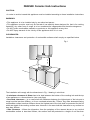
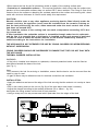
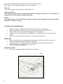
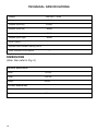
UK
VITROCERAMIC HOB
Operating instructions book
2
DHHS80 Ceramic Hob Instructions
CAUTION:
• In order to avoid a hazard this appliance must be installed according to these installation instructions
WARNING:
• This appliance is to be installed only by an authorized person
• This appliance must be used only for the task it has explicitly been designed for, that is for cooking
foodstuffs. Any other form of usage is to be considered as inappropriate and therefore dangerous.
• Do NOT place combustible materials or products on this appliance at any time
• Do NOT spray aerosols in the vicinity of this appliance while it is in use.
CLEARANCES:
Installation clearances and protection of combustible surfaces shall comply as specified below.
750 mm
450 mm
Fig.1
The installation will comply with the dimensions in Fig. 1 bearing in mind that:
• A minimum clearance of 60mm has to be kept between the bottom of the cooking hob and the top
of an appliance or a thermal barrier (see next page)
• Overhead clearances – In no case shall the clearances between the highest part of the hob and a
range hood be less than 650mm, or for an overhead exhaust fan, 750mm. Any other downward facing
combustible surface less than 600mm above the highest part of the hob shall be protected for the full
width and depth of the cooking surface area. However in no case shall this clearance to any surface be
less than 450mm.
• Side Clearance – Where the dimension from the periphery of the nearest burner to any vertical
combustible surface is less than 200mm, the surface shall be protected to a height of not less than
3
150mm above the hob for the full dimension (width or depth) of the cooking surface area.
• Protection of combustible surfaces – The required protection shall ensure that the surface temperature of the combustible surface does not exceed 50°C above ambient. The fixing of 5mm thick
ceramic tiles to the surface or attaching fire resistant material to the surface and covering with sheet
metal with minimum thickness of 0.4mm would satisfy this requirement.
CAUTION:
Should a built-in oven or any other appliance producing heat be fitted directly under the
ceramic cook-top, the appliance (oven) must be insulated from the ceramic cook-top so
that the heat produced by the oven, when measured under the touch control side of the
hob does not exceed 60°C.
The underside surface of the cooking hob can reach a temperature exceeding 105°C during normal use.
If after installation the underside surface is accessible through under bench cupboards
and the like, it is essential that a rigid barrier is installed so that such access is restricted.
In order to avoid a hazard the barrier must be of low thermal conductivity material installed according to the instructions for installation.
THE APPLIANCE IS NOT INTENDED FOR USE BY YOUNG CHILDREN OR INFIRM PERSONS
WITHOUT SUPERVISION.
YOUNG CHILDREN SHOULD BE SUPERVISED TO ENSURE THAT THEY DO NOT PLAY WITH
THE APPLIANCE.
THERMAL BARRIER INSTALLATION:
WARNING:
• If the hob is installed over drawers or cupboards, a thermal protection barrier must be fitted at
least 60mm beneath the base of the hob.
(see Fig. 1)
Note:
• For access to the hob for servicing or installation, ensure that the barrier can be removed from beneath by use of a tool.
• A gap of 20mm may be allowed at rear for electrical connection and ventilation.
INSTALLATION:
• Apply the adhesive seal around the edge of the hob ensuring that the ends do not overlap or leave
a gap.
• Slot in the cooking hob into the cut-out (fig. 2b) of the work bench and locate it correctly.
• Adjust the clamps according to the worktop thickness (30 or 40mm – fig. 2a)
and tighten the fixing screws until the hob is firmly secured.
• Using a sharp tool, trim any excess seal which protrudes from the edges of the hob.
Fig.2a
Fig.2b
30 mm
0
49
53
,5
43
40 mm
4
50
min.
560/750
50
min.
ELECTRICAL REQUIREMENTS:
If you wish a direct connection to the line, it is necessary to interpose a single-pole switch,
with a minimum opening between the contacts of 3 mm, suitable for the load indicated in
the plate and in conformity with the rules in force (the yellow/green ground cable should
not be interrupted by the switch).
The single pole switch should be easily accessible with appliance installed.
WARNING:
• THIS APPLIANCE MUST BE EARTHED.
• In order to avoid a hazard this appliance must be installed according to these instructions for installation.
CAUTION:
• Ensure that the power outlet is properly earthed before connecting the appliance.
• Disconnect power before servicing the appliance.
• Connect wiring at hob in accordance with connection diagram fig. 3.
A double pole switch must be provided no further than 2 metres from the appliance to the electrical
supply. All supply current and earth conductors must be able to withstand an ambient temperature of
75°C.
The wires in the power cable must be coloured in accordance with the following code:
Green/yellow = Earth, Blue = Neutral, Brown = Active or live.
Fig.3
FEEDER CABLE SELECTION
230V~
3 x 2.5 mm² (*)
240V~
3 x 2.5 mm² (*)
(*) – Connection with wall box
WARNING: THIS HOB MUST BE
CONNECTED TO SUPPLY USING
V105 INSULATED CABLE
220-240 V~ H05RR-F 2.5mm
2
3
4
4
1
L
2
2
220-240 V2~ H05RR-F 2.5mm
1
2
3
4
4
N
L1
2
380-415 V2N~ H05RR-F 2.5mm
4
4
1
2
3
L1
L2
N
L2
2
220-240 V3~ H05RR-F 2.5mm
1
2
3
4
4
L1
L2
L3
2
380-415 V3N~ H05RR-F 2.5mm
1
2
3
4
4
L1
L2
L3
N
USE and CARE
CAUTION:
• This appliance must be used for the task it has explicitly been designed for,
that is for cooking foodstuffs. Any other form of usage is to be considered as
inappropriate and therefore dangerous.
• Do NOT place combustible materials or products on this appliance at any time.
• Do NOT spray aerosols in the vicinity of this appliance while it is in use.
• Before using for the first time, clean the cooktop with warm soapy water.
We recommend that you run each plate individually for several minutes.
To do this, place a saucepan of water on each plate in turn, and bring the
water to the boil. During this procedure the room should be well ventilated, as there may be an emission of smoke and a slight odour.
5
HOTPLATES:
The heating elements are formed by a coil of resistant material which reaches the working temperature quickly.
Warning for the eyes: Do not stare at the hotplates when they are on.
TOUCH CONTROL OPERATION:
i) The very first time power is connected to the cook-top, it will be in locked mode for safety.
ii) To begin any operation, touch the
lock key for 3 seconds.
iii) To turn on an element, touch the corresponding
on/off key.
The power level indicator LED at position 5 will flash.
Press the
minus key within 10 seconds to reduce power, or the
plus key within 10 seconds
to increase power.
iv) To switch off the element, press the
on/off key.
v) It is possible to lock the element on during operation by touching the lock key for 3 seconds.
vi) To switch off the element while in locked mode, press the
lock key for 3 seconds followed
by the on/off key.
Note: If an object is placed over the hob control, or if liquid is spilled over the controls, the cooktop
will automatically turn off. If the cooktop is fitted with extended elements, the second zone will
turn on by holding down the extended plus key for that element for 3 seconds.
The power level for that element can then be set by touching the
plus or
minus keys.
After an element is turned off & the surface temperature of the plate is higher than 50°C, the temperature indicator LED’s will flash until the surface temperature drops below 50°C.
TIMER OPERATION
The timer can be set to automatically turn the cooktop off after a preset time
(from 1 - 99 mins).
To set the timer, perform the following steps:
·Touch the
timer key A (Fig. 6) to select the cooking area which, previously turned on, which
will be displayed on indicator B (Fig. 6)
·Set the desired cooking time using the
plus or
minus keys in the timer area.
·If the timer has been set to turn off more than one element, the LED indicator in the timer area will
show time remaining for each element every 3 seconds.
·The elements which are in timer mode can be identified by the first power level indicator LED
flashing for that element.
·The timer function can be turned off by touching
on/off key D (Fig. 6).
TIMER
SAFETY HINTS
·Never put cooking foil or plastic materials on the ceramic surface when the hob is hot.
·Make sure that the hob is clean before you use it.
·Remember that the plates will remain hot for approximately half an hour after the plate has been
switched off.
·Before you switch the hob on, make sure you know what controls turn each element on. We
recommend you to set the pan over the cooking
plate before switching it on.
·Pan handles should never stand beyond the kitchen work top. This will ensure children cannot
reach them.
·Do not use pans with rough bases as these may scratch the hob surface.
6
·
·Please turn the appliance off at the mains and call your nearest DeLonghi Service Agent.
·Do not lean over the cooking plate when in use.
·Follow the cleaning instructions carefully.
·Always ensure the base of your sausepan is clean & dry before placing on the hob.
·Never use the glass surface for storage.
·Do not scratch the cooktop with cutting utensils or sharp objects. Do not use the glass ceramic
cooktop as a work surface.
·Caution – never cook the food directly on the ceramic hob! Always use a saucepan or
special container.
·DO NOT use the hob if the glass surface is broken or cracked in any way.
WARNING:
If the surface is cracked, switch off the appliance to avoid the possibility of electric
shock
WARNING:
·HOBS BECOME VERY HOT WITH USE, AND RETAIN THEIR HEAT FOR A LONG TIME AFTER
COOKING HAS FINISHED. CHILDREN SHOULD BE SUPERVISED AT ALL TIMES AND BE PREVENTED FROM TOUCHING THE HOT SURFACES UNTIL SUCH TIME AS THE APPLIANCE HAS
COOLED.
Fig.4
COOKING HINTS:
• Please note that you will quickly learn from experience which setting is correct for your needs.
ECONOMIC COOKING
• The ceramic glass retains heat, so you may find that you can switch off the heat 5 minutes before you finish cooking.
• To reduce the cooking time, the plate can be set to the maximum setting at the beginning. It can
then be reduced later.
COOKWARE:
It is very important that the pans used on the hobs are made of a suitable material and have the
correct base as follows:
• The base should be flat and smooth
• Any rough part on the pan base could scratch the hob surface.
• Choose pans which are the same size as the hotplates and with bases that are as 0non reflective as possible eg. dull and dark.
7
Only pans recommended for use on ceramic hobs should be used.
Pans made of the following materials can cause problems:
Cast Iron
- The base may be rough which will scratch the hob.
Toughened Glass
- If the pan becomes too hot, the hob may overheat causing the safety cut out to operate too
frequently thus reducing the cooking efficiency.
Copper
- Can easily distort and will therefore not form a good contact between base and hob which
will result in uneven cooking.
CLEANING AND MAINTENANCE
•
•
•
•
•
Before you begin cleaning you must ensure that the hob is switched off.
Remove spillages and other types of incrustations by using the scraper (Fig 5)
Remove any dust, food particles or spillages with a damp cloth.
Spillages must be cleaned away immediately. This is essential in the case of sugar mixtures.
Make sure that all traces of cleaner are removed with a soft cloth
IMPORTANT
•
Sugar or syrup mixtures can permanently damage the hob surface if left on to burn
•
Never use abrasive cleaning products on the hob.
•
If anything melts on the glass remove it immediately whilst the surface is still hot.
•
Do not use knives or sharp utensils on the hob.
•
Do not use steam jet cleaners.
STAINLESS STEEL:
•
Clean with a suitable product. Always dry thoroughly.
Fig.5
8
TOUCH CONTROL PANEL DESCRIPTION
Fig.6
10
50
90
1
5
9
Timer Area
Timer display
Timer Control Keys
Cooking area selection and display
TIMER
B
1
A
5
9
Heat positions
C
Heat setting Keys
1
5
9
Control Area
Extended area display
1
5
9
Heating zone indicator
On/Off Key
1
5
9
Key-lock On / Off pilot light
Extended area display
Lock key - Hold down for 3 seconds
to turn on or off
9
TECHNICAL SPECIFICATIONS
Voltage
220-240V ~ 50 Hz
Max. power
6.7 kW
Hotplate (front left)
2100W
Hotplate (back left)
1200W
Hotplate (back right)
2200W
Hotplate (front right)
1200W
Touch Control
Residual heat indicator warning LED’s
Glass overheat cut-out device
1
DIMENSIONS
(Note: Also refer to Fig. 2)
General Dimensions
Width
770 mm
Depth
510 mm
Height
48 mm
Cut-out Dimensions
Width
750 mm
Depth
490 mm
10
11
94000STISPE0DG_18/06/2002