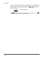
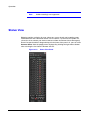
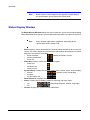
Download CCTV iDVR-RT16 User guide

Transcript
RASplus (Remote
Administration System)
Digital Video Recorder Software
User Guide
Document 800-05056 – Rev C – 11/09
Revisions
Issue
Date
Revisions
A
09/09
New document based on 900.0857 rev 6.00 with updates for V1.4.4 to
include HRXDS.
B
09/09
On page 12, updated p/n of HRSD user guide and corrected HRXDS16
model name.
C
11/09
Updated back cover
2
Contents
Contents
About This Document . . . . . . . . . . . . . . . . . . . . . . . . . . . . . . . . . . . . . . 11
Overview of Contents . . . . . . . . . . . . . . . . . . . . . . . . . . . . . . . . . . . . . . 11
Related Documents . . . . . . . . . . . . . . . . . . . . . . . . . . . . . . . . . . . . . . . 11
1
Overview . . . . . . . . . . . . . . . . . . . . . . . . . . . . . . . . . . . . . . . . . . . 13
Features . . . . . . . . . . . . . . . .
Product Information . . . . . . . . . .
Package Components.
System Requirements .
2
.
.
.
.
.
.
.
.
.
.
.
.
.
.
.
.
.
.
.
.
.
.
.
.
.
.
.
.
.
.
.
.
.
.
.
.
.
.
.
.
.
.
.
.
.
.
.
.
.
.
.
.
.
.
.
.
.
.
.
.
.
.
.
.
.
.
.
.
.
.
.
.
.
.
.
.
.
.
.
.
.
.
.
.
.
.
.
.
.
.
.
.
.
.
.
.
.
.
.
.
.
.
.
.
.
.
.
.
.
.
.
.
.
.
.
.
13
14
14
14
Installation . . . . . . . . . . . . . . . . . . . . . . . . . . . . . . . . . . . . . . . . . . 15
Installing RASplus . . . . . . . . . . . . . . . . . . . . . . . . . . . . . . . . . . . . . . . . 15
3
Configuration . . . . . . . . . . . . . . . . . . . . . . . . . . . . . . . . . . . . . . . . 21
RASplus Viewing Screen . . . . . . . . . . . . . . . . .
RASplus Panel. . . . . . . . . . . . . . . . . . . . . . .
Remote Sites Panel . . . . . . . . . . . .
Favorite Sites Panel . . . . . . . . . . . .
Status View Panel . . . . . . . . . . . . .
Search View Panel. . . . . . . . . . . . .
Map Panel . . . . . . . . . . . . . . . . .
Color, PTZ, and Alarm Out Control Panels
Image Processing Panel. . . . . . . . . .
Emergency Event View Panel . . . . . . .
Watch Event View Panel. . . . . . . . . .
Report View Panel . . . . . . . . . . . . .
RASplus Menus . . . . . . . . . . . . . . . . . . . . . .
System Menu . . . . . . . . . . . . . . .
View Menu . . . . . . . . . . . . . . . . .
Remote Menu . . . . . . . . . . . . . . .
Favorite Menu . . . . . . . . . . . . . . .
Sequence Menu . . . . . . . . . . . . . .
Record Menu . . . . . . . . . . . . . . .
Image Menu . . . . . . . . . . . . . . . .
Layout Menu . . . . . . . . . . . . . . . .
Help Menu . . . . . . . . . . . . . . . . .
Toolbar . . . . . . . . . . . . . . . . . . . . . . . . . .
4
.
.
.
.
.
.
.
.
.
.
.
.
.
.
.
.
.
.
.
.
.
.
.
.
.
.
.
.
.
.
.
.
.
.
.
.
.
.
.
.
.
.
.
.
.
.
.
.
.
.
.
.
.
.
.
.
.
.
.
.
.
.
.
.
.
.
.
.
.
.
.
.
.
.
.
.
.
.
.
.
.
.
.
.
.
.
.
.
.
.
.
.
.
.
.
.
.
.
.
.
.
.
.
.
.
.
.
.
.
.
.
.
.
.
.
.
.
.
.
.
.
.
.
.
.
.
.
.
.
.
.
.
.
.
.
.
.
.
.
.
.
.
.
.
.
.
.
.
.
.
.
.
.
.
.
.
.
.
.
.
.
.
.
.
.
.
.
.
.
.
.
.
.
.
.
.
.
.
.
.
.
.
.
.
.
.
.
.
.
.
.
.
.
.
.
.
.
.
.
.
.
.
.
.
.
.
.
.
.
.
.
.
.
.
.
.
.
.
.
.
.
.
.
.
.
.
.
.
.
.
.
.
.
.
.
.
.
.
.
.
.
.
.
.
.
.
.
.
.
.
.
.
.
.
.
.
.
.
.
.
.
.
.
.
.
.
.
.
.
.
.
.
.
.
.
.
.
.
.
.
.
.
.
.
.
.
.
.
.
.
.
.
.
.
.
.
.
.
.
.
.
.
.
.
.
.
.
.
.
.
.
.
.
.
.
.
.
.
.
.
.
.
.
.
.
.
.
.
.
.
.
.
.
.
.
.
.
.
.
.
.
.
.
.
.
.
.
.
.
.
.
.
.
.
.
.
.
.
.
.
.
.
.
.
.
.
.
.
.
.
.
.
.
.
.
.
.
.
.
.
.
.
.
.
.
.
.
.
.
.
.
.
.
.
.
.
.
.
.
.
.
.
.
.
.
.
.
.
.
.
.
.
.
.
.
.
.
.
.
.
.
.
.
.
.
.
.
.
.
.
.
.
.
.
.
.
.
22
24
25
26
27
28
28
31
32
32
33
34
34
35
49
50
51
52
52
53
53
56
56
Operation . . . . . . . . . . . . . . . . . . . . . . . . . . . . . . . . . . . . . . . . . . 59
Live Monitoring . . . . . . . . . . . . . . . . . . . . . . . . . . . . . . . . . . . . . . . . . 59
Screen Layout and Frame Layout . . . . . . . . . . . . . . . . . . . . . . . . 60
Document 800-05056 Rev C
11/09
3
Contents
Audio Communication
Sequence Monitoring .
Playback and Search . . . . . . . . .
Search View Panel . .
Search Mode . . . . .
Additional Functions .
Panic Recording . . . . . . . . . . .
Status View . . . . . . . . . . . . . .
Function Buttons . . .
Status Display Window
Appendix A
.
.
.
.
.
.
.
.
.
.
.
.
.
.
.
.
.
.
.
.
.
.
.
.
.
.
.
.
.
.
.
.
.
.
.
.
.
.
.
.
.
.
.
.
.
.
.
.
.
.
.
.
.
.
.
.
.
.
.
.
.
.
.
.
.
.
.
.
.
.
.
.
.
.
.
.
.
.
.
.
.
.
.
.
.
.
.
.
.
.
.
.
.
.
.
.
.
.
.
.
.
.
.
.
.
.
.
.
.
.
.
.
.
.
.
.
.
.
.
.
.
.
.
.
.
.
.
.
.
.
.
.
.
.
.
.
.
.
.
.
.
.
.
.
.
.
.
.
.
.
.
.
.
.
.
.
.
.
.
.
.
.
.
.
.
.
.
.
.
.
.
.
.
.
.
.
.
.
.
.
.
.
.
.
.
.
.
.
.
.
.
.
.
.
.
.
.
.
.
.
.
.
.
.
.
.
.
.
.
.
.
.
.
.
.
.
.
.
.
.
.
.
.
.
.
.
.
.
.
.
.
.
.
.
.
.
.
.
.
.
.
.
.
.
.
.
.
.
.
.
.
.
.
.
.
.
.
.
.
.
.
.
.
.
.
.
.
.
.
.
.
.
.
.
.
.
.
.
.
.
.
.
.
.
.
.
.
.
.
.
.
.
.
.
.
.
.
.
.
.
.
.
.
.
.
.
.
.
.
.
.
.
.
.
.
.
.
.
.
60
61
64
65
66
70
75
77
78
79
80
Video Clips Review. . . . . . . . . . . . . . . . . . . . . . . . . . . . . . . 81
MiniBank Player . . . . . . . . . . . . . . . . . . . . . . . . . . . . . . . . . . . . . . . . 81
Clip Player . . . . . . . . . . . . . . . . . . . . . . . . . . . . . . . . . . . . . . . . . . . 83
Appendix B
DVR Name Service (DVRNS) . . . . . . . . . . . . . . . . . . . . . . . . . 89
System Configuration . . . . . . . . . . . . . . . . . . . . . . . . . . . . . . . . . . . . . 89
Appendix C
Map Editor . . . . . . . . . . . . . . . . . . . . . . . . . . . . . . . . . . . 91
Background Image Setting .
Option Menu . . . . . . . .
Device Setting . . . . . . .
Link Setting . . . . . . . . .
4
.
.
.
.
.
.
.
.
.
.
.
.
.
.
.
.
.
.
.
.
.
.
.
.
.
.
.
.
.
.
.
.
.
.
.
.
.
.
.
.
.
.
.
.
.
.
.
.
.
.
.
.
.
.
.
.
.
.
.
.
.
.
.
.
.
.
.
.
.
.
.
.
.
.
.
.
.
.
.
.
.
.
.
.
.
.
.
.
.
.
.
.
.
.
.
.
.
.
.
.
.
.
.
.
.
.
.
.
.
.
.
.
.
.
.
.
.
.
.
.
.
.
.
.
.
.
.
.
.
.
.
.
.
.
.
.
92
92
95
98
Figures
Figures
Figure 2-1
Select Installation Folder . . . . . . . . . . . . . . . . . . . . . . . . . . . . . . . 16
Figure 2-2
Welcome to RASplus Setup Wizard . . . . . . . . . . . . . . . . . . . . . . . . . 16
Figure 2-3
RASplus Ready to Install . . . . . . . . . . . . . . . . . . . . . . . . . . . . . . . 17
Figure 2-4
Run RASplus Automatically Option . . . . . . . . . . . . . . . . . . . . . . . . . 17
Figure 2-5
RASplus Language Option . . . . . . . . . . . . . . . . . . . . . . . . . . . . . . 18
Figure 2-6
RASplus Exit Setup . . . . . . . . . . . . . . . . . . . . . . . . . . . . . . . . . . 18
Figure 2-7
Welcome to MSXML Setup Wizard. . . . . . . . . . . . . . . . . . . . . . . . . . 19
Figure 2-8
MSXML End-User License Agreement . . . . . . . . . . . . . . . . . . . . . . . . 19
Figure 2-9
MSXML Customer Information . . . . . . . . . . . . . . . . . . . . . . . . . . . . 19
Figure 2-10
MSXML Choose Setup Type . . . . . . . . . . . . . . . . . . . . . . . . . . . . . 20
Figure 2-11
MSXML Exit Setup . . . . . . . . . . . . . . . . . . . . . . . . . . . . . . . . . . 20
Figure 3-1
RASplus Viewing Screen . . . . . . . . . . . . . . . . . . . . . . . . . . . . . . . 22
Figure 3-2
Four Position Arrow Icon . . . . . . . . . . . . . . . . . . . . . . . . . . . . . . . 25
Figure 3-3
Four Position Arrow with Tab Icon . . . . . . . . . . . . . . . . . . . . . . . . . . 25
Figure 3-4
Remote Sites Panel. . . . . . . . . . . . . . . . . . . . . . . . . . . . . . . . . . 25
Figure 3-5
Favorite Sites Panel . . . . . . . . . . . . . . . . . . . . . . . . . . . . . . . . . 26
Figure 3-6
Status View Panel . . . . . . . . . . . . . . . . . . . . . . . . . . . . . . . . . . 27
Figure 3-7
Search View Panel . . . . . . . . . . . . . . . . . . . . . . . . . . . . . . . . . . 28
Figure 3-8
Map Panel . . . . . . . . . . . . . . . . . . . . . . . . . . . . . . . . . . . . . . 28
Figure 3-9
Map Image . . . . . . . . . . . . . . . . . . . . . . . . . . . . . . . . . . . . . . 29
Figure 3-10
Map Popup Options Menu . . . . . . . . . . . . . . . . . . . . . . . . . . . . . . 30
Figure 3-11
Color, PTZ and Alarm Out Control Panels . . . . . . . . . . . . . . . . . . . . . . 31
Figure 3-12
Image Processing Panel . . . . . . . . . . . . . . . . . . . . . . . . . . . . . . . 32
Figure 3-13
Emergency Event View Panel . . . . . . . . . . . . . . . . . . . . . . . . . . . . 32
Figure 3-14
Watch Event View Panel . . . . . . . . . . . . . . . . . . . . . . . . . . . . . . . 33
Figure 3-15
Report View Panel . . . . . . . . . . . . . . . . . . . . . . . . . . . . . . . . . . 34
Figure 3-16
RASplus Menu Bar . . . . . . . . . . . . . . . . . . . . . . . . . . . . . . . . . . 34
Figure 3-17
System Menu . . . . . . . . . . . . . . . . . . . . . . . . . . . . . . . . . . . . . 35
Figure 3-18
Setup Screen — System 1 . . . . . . . . . . . . . . . . . . . . . . . . . . . . . . 35
Figure 3-19
Drawing Mode Screen . . . . . . . . . . . . . . . . . . . . . . . . . . . . . . . . 36
Figure 3-20
Recording Mode Setup Screen . . . . . . . . . . . . . . . . . . . . . . . . . . . 38
Figure 3-21
Setup Screen — System 2 . . . . . . . . . . . . . . . . . . . . . . . . . . . . . . 39
Figure 3-22
Event Setup Screen . . . . . . . . . . . . . . . . . . . . . . . . . . . . . . . . . 40
Document 800-05056 Rev C
11/09
5
Figures
6
Figure 3-23
Screen Setup — Remote Sites . . . . . . . . . . . . . . . . . . . . . . . . . . . 41
Figure 3-24
Add Site Screen . . . . . . . . . . . . . . . . . . . . . . . . . . . . . . . . . . . 41
Figure 3-25
Setup Screen — Favorite Sites . . . . . . . . . . . . . . . . . . . . . . . . . . . 43
Figure 3-26
Setup Screen — Sequence Sites . . . . . . . . . . . . . . . . . . . . . . . . . . 45
Figure 3-27
Batch Job Setup Screen — Upgrade . . . . . . . . . . . . . . . . . . . . . . . . 46
Figure 3-28
Batch Job Setup Screen . . . . . . . . . . . . . . . . . . . . . . . . . . . . . . . 47
Figure 3-29
Log Setup Screen . . . . . . . . . . . . . . . . . . . . . . . . . . . . . . . . . . 48
Figure 3-30
View Menu . . . . . . . . . . . . . . . . . . . . . . . . . . . . . . . . . . . . . . 49
Figure 3-31
Remote Menu . . . . . . . . . . . . . . . . . . . . . . . . . . . . . . . . . . . . 50
Figure 3-32
Remote System/Event Log . . . . . . . . . . . . . . . . . . . . . . . . . . . . . 51
Figure 3-33
Favorite Menu . . . . . . . . . . . . . . . . . . . . . . . . . . . . . . . . . . . . 52
Figure 3-34
Sequence Menu . . . . . . . . . . . . . . . . . . . . . . . . . . . . . . . . . . . 52
Figure 3-35
Record Menu. . . . . . . . . . . . . . . . . . . . . . . . . . . . . . . . . . . . . 52
Figure 3-36
Image Menu . . . . . . . . . . . . . . . . . . . . . . . . . . . . . . . . . . . . . 53
Figure 3-37
Layout Menu . . . . . . . . . . . . . . . . . . . . . . . . . . . . . . . . . . . . . 53
Figure 3-38
Screen Layout . . . . . . . . . . . . . . . . . . . . . . . . . . . . . . . . . . . . 54
Figure 3-39
Frame Layout . . . . . . . . . . . . . . . . . . . . . . . . . . . . . . . . . . . . 54
Figure 3-40
Layout Load . . . . . . . . . . . . . . . . . . . . . . . . . . . . . . . . . . . . . 55
Figure 3-41
Layout Setup . . . . . . . . . . . . . . . . . . . . . . . . . . . . . . . . . . . . . 55
Figure 3-42
RASplus Toolbars . . . . . . . . . . . . . . . . . . . . . . . . . . . . . . . . . . 56
Figure 3-43
RASplus Controls Toolbar
Figure 3-44
Screen Layout Toolbar. . . . . . . . . . . . . . . . . . . . . . . . . . . . . . . . 56
Figure 3-45
Frame Layout Toolbar . . . . . . . . . . . . . . . . . . . . . . . . . . . . . . . . 57
. . . . . . . . . . . . . . . . . . . . . . . . . . . . . 56
Figure 4-1
Watch Search Screen Selection . . . . . . . . . . . . . . . . . . . . . . . . . . . 60
Figure 4-2
Screen Layout Toolbar. . . . . . . . . . . . . . . . . . . . . . . . . . . . . . . . 60
Figure 4-3
Audio Communication Menu . . . . . . . . . . . . . . . . . . . . . . . . . . . . 61
Figure 4-4
Select Audio Channel Dialog Box . . . . . . . . . . . . . . . . . . . . . . . . . . 61
Figure 4-5
Color Controls . . . . . . . . . . . . . . . . . . . . . . . . . . . . . . . . . . . . 62
Figure 4-6
PTZ Controls . . . . . . . . . . . . . . . . . . . . . . . . . . . . . . . . . . . . . 63
Figure 4-7
Alarm Out Controls . . . . . . . . . . . . . . . . . . . . . . . . . . . . . . . . . 63
Figure 4-8
Watch Search Screen Selection . . . . . . . . . . . . . . . . . . . . . . . . . . . 64
Figure 4-9
Search View Panel . . . . . . . . . . . . . . . . . . . . . . . . . . . . . . . . . . 65
Figure 4-10
Time-Lapse Search Screen . . . . . . . . . . . . . . . . . . . . . . . . . . . . . 66
Figure 4-11
Selecting a Video Segment . . . . . . . . . . . . . . . . . . . . . . . . . . . . . 67
Figure 4-12
Event Search Panel . . . . . . . . . . . . . . . . . . . . . . . . . . . . . . . . . 68
Figure 4-13
Event Search Dialog Box . . . . . . . . . . . . . . . . . . . . . . . . . . . . . . 68
Figure 4-14
Event Search Text-In Dialog Box . . . . . . . . . . . . . . . . . . . . . . . . . . 68
Figure 4-15
Text-In Event Search Dialog Box . . . . . . . . . . . . . . . . . . . . . . . . . . 70
Figure 4-16
Search Data Source Screen . . . . . . . . . . . . . . . . . . . . . . . . . . . . . 71
Figure 4-17
Screen Format Toolbar . . . . . . . . . . . . . . . . . . . . . . . . . . . . . . . 71
Figure 4-18
Image Processing Panel . . . . . . . . . . . . . . . . . . . . . . . . . . . . . . . 71
Figure 4-19
Save Type Screen . . . . . . . . . . . . . . . . . . . . . . . . . . . . . . . . . . 72
Figure 4-20
Save As Self-Player . . . . . . . . . . . . . . . . . . . . . . . . . . . . . . . . . 73
Figures
Figure 4-21
Save As Video Screen . . . . . . . . . . . . . . . . . . . . . . . . . . . . . . . . 74
Figure 4-22
Camera Popup Menu. . . . . . . . . . . . . . . . . . . . . . . . . . . . . . . . . 75
Figure 4-23
Status View Panel . . . . . . . . . . . . . . . . . . . . . . . . . . . . . . . . . . 78
Figure A-1
MiniBank Self Player User Interface . . . . . . . . . . . . . . . . . . . . . . . . . 82
Figure A-2
Clip Player User Interface . . . . . . . . . . . . . . . . . . . . . . . . . . . . . . 84
Figure A-3
Clip Player Menu . . . . . . . . . . . . . . . . . . . . . . . . . . . . . . . . . . . 85
Figure A-4
Save Clip Images Menu . . . . . . . . . . . . . . . . . . . . . . . . . . . . . . . 86
Figure B-1
DVRNS Server System Configuration . . . . . . . . . . . . . . . . . . . . . . . . 89
Figure C-1
Map Editor . . . . . . . . . . . . . . . . . . . . . . . . . . . . . . . . . . . . . . 91
Figure C-2
Property [Canvas] Tab . . . . . . . . . . . . . . . . . . . . . . . . . . . . . . . . 92
Figure C-3
Option Menu . . . . . . . . . . . . . . . . . . . . . . . . . . . . . . . . . . . . . 92
Figure C-4
Site Information Window . . . . . . . . . . . . . . . . . . . . . . . . . . . . . . . 92
Figure C-5
Site Item Window . . . . . . . . . . . . . . . . . . . . . . . . . . . . . . . . . . . 93
Figure C-6
Popup Dwell Time Dialog Box . . . . . . . . . . . . . . . . . . . . . . . . . . . . 93
Figure C-7
Status Color Window . . . . . . . . . . . . . . . . . . . . . . . . . . . . . . . . . 94
Figure C-8
Name Table Window . . . . . . . . . . . . . . . . . . . . . . . . . . . . . . . . . 95
Figure C-9
Property [Camera/AlarmOut/AlarmIn] Tab . . . . . . . . . . . . . . . . . . . . . . 95
Figure C-10
Event [Camera] Tab . . . . . . . . . . . . . . . . . . . . . . . . . . . . . . . . . 97
Figure C-11
Event [AlarmOut] Tab . . . . . . . . . . . . . . . . . . . . . . . . . . . . . . . . 97
Figure C-12
Event [AlarmIn] Tab . . . . . . . . . . . . . . . . . . . . . . . . . . . . . . . . . 97
Figure C-13
Property [Link] Tab . . . . . . . . . . . . . . . . . . . . . . . . . . . . . . . . . . 98
Document 800-05056 Rev C
11/09
7
Figures
8
Tables
Tables
Table 4-1
Camera Popup Menu Options . . . . . . . . . . . . . . . . . . . . . . . . . . . . 76
Table A-1
Clip Player Menu Functions . . . . . . . . . . . . . . . . . . . . . . . . . . . . . . 85
Table 4-5
Save Clip Images Options. . . . . . . . . . . . . . . . . . . . . . . . . . . . . . . 86
Table C-1
Property Tab Device Information . . . . . . . . . . . . . . . . . . . . . . . . . . . 95
Table C-2
Property Tab Device Information . . . . . . . . . . . . . . . . . . . . . . . . . . . 98
Document 800-05056 Rev C
11/09
9
Tables
10
About This Document
This document introduces the Remote Administration System Plus (RASplus) software
designed for the digital video recorder (DVR) and describes the procedures for
operating and maintaining the software.
Overview of Contents
This document contains the following chapters and appendixes:
•
•
•
•
•
•
•
Chapter 1, Overview, describes the Remote Administration System and lists its
features.
Chapter 2, Installation, provides the procedures necessary to install RASplus.
Chapter 3, Configuration, covers the configurations and settings available with
RASplus.
Chapter 4, Operation, provides the procedures necessary for RASplus operation.
Appendix A, Video Clips Review, covers the functions and features of the MiniBank
Self Player program.
Appendix B, DVR Name Service (DVRNS), explains how to set up a remote DVR
using a DVRNS server.
Appendix C, Map Editor, describes the map editor and its features.
Related Documents
For more information about topics that are relevant to the subject of this manual, see
the documents listed below.
Document 800-05056 Rev C
11/09
Document title
Part number
HRXD9, HRXD16 DVR User Guide
900.0856
DVRNS Server for DVRs User Guide
800-05057
11
12
Document title(cont’d)
Part number
HRSD4 DVR User Guide
800-00919
HRSD8, HRSD16 DVR User Guide
800-03650
HRXDS8, HRXDS16 DVR User Guide
800-04559
Overview
1
Overview
This manual describes the installation and operation of RASplus (Remote
Administration System Plus) software, which is designed to be used with remote digital
video recorders (DVRs).
Features
RASplus is an integrated software program that controls system management, video
monitoring, video recording, and image playback of multiple remotely connected sites.
RASplus offers the following features:
•
•
•
•
•
•
•
•
•
Checks and reports status of remote DVRs
Notification of events detected at remote sites
Remote monitoring of live camera images
One-touch panic recording of currently displayed images
Time-lapse and event searching of recorded images
Remote software upgrades and system programming
View system and event log information of remote DVRs
Remote monitoring of multiple remote sites using 3D maps
Connect up to 64 remote sites (up to 16 remote sites for remote search) at a time
Note
Document 800-05056 Rev C
11/09
This product includes software developed by the OpenSSL
Project for use in the OpenSSL Toolkit (http://openssl.org/).
13
Overview
Product Information
Package Components
•
•
•
RASplus User Guide (this document)
Multilingual RASplus Software and User Guide (RASplus CD-ROM)
DVRNS Server Software and User Guide (RASplus CD-ROM)
System Requirements
Playing back digital video puts a high demand on your computer system. To use the
RASplus video monitoring and playback functions, your personal computer (PC) must
meet the minimum system requirements listed below:
•
•
•
•
14
Operating System: Microsoft Windows XP x86 (32 Bit) or Microsoft Windows Vista
x86 (32 Bit)
CPU: Intel Pentium IV (Celeron) 2.4 GHz or faster
RAM: 512 MB or higher
VGA: AGP, Video RAM 8 MB or higher (1024x768, 24 bpp or higher)
Installation
2
Installation
Installing RASplus
Caution
If an older version of RASplus has already been installed on your
computer, you should uninstall the older version before installing
the new one.
Note
In the Start menu in Windows, go to your Control Panel.
Double-click Power Options to open the Management
Properties dialog box. Under the Power Schemes tab, set both
Turn off monitor and Turn off hard disks to Never.
Note
The User Account Control window might appear when using
the Microsoft Windows Vista operating system. Click Allow and
install RASplus software following the instructions.
1.
Insert the installation CD.
2.
Run the Setup.exe file.
Document 800-05056 Rev C
11/09
15
Installation
3.
The .NET Framework and the Visual C++ Runtime Libraries are installed
automatically.
Note
4.
Installing .NET Framework and the Visual C++ Runtime
Libraries is required for RASplus to operate properly. This
installation step will be skipped if they are already installed on
your computer.
Designate the folder path to install RASplus and select the user(s) who can use
RASplus, then click Next.
Figure 2-1
5.
When Figure 2-2 appears, click Next.
Figure 2-2
16
Select Installation Folder
Welcome to RASplus Setup Wizard
Installation
6.
Click Next.
Figure 2-3
7.
Select whether or not to run RASplus automatically when logging onto Windows,
and then click Next.
Figure 2-4
8.
RASplus Ready to Install
Run RASplus Automatically Option
Set the language option by selecting either Select language when starting
RASplus or Always start RASplus using the language below. If you select to
Always start RASplus using the language below, select the desired startup
language from the list of available languages and then click OK.
Document 800-05056 Rev C
11/09
17
Installation
Figure 2-5
9.
Note
To properly display the selected language, your PC’s operating
system should be set up to support the selected language.
Note
To change RASplus’ language after selecting the Always start
RASplus using the language below option, the RASplus
software must be re-installed.
When Figure 2-6 appears after finishing the RASplus installation, select the Install
MSXML check box and click Finish. Installing the MSXML application is required
for RASplus to initiate.
Figure 2-6
10. Click Next.
18
RASplus Language Option
RASplus Exit Setup
Installation
Figure 2-7
Welcome to MSXML Setup Wizard
11. Select I accept the terms in the License Agreement, and click Next.
Figure 2-8
MSXML End-User License Agreement
12. Enter a User Name and Organization, and click Next.
Figure 2-9
Document 800-05056 Rev C
11/09
MSXML Customer Information
19
Installation
13. Select Install Now.
Figure 2-10
MSXML Choose Setup Type
14. Click Finish to complete the MSXML installation.
Figure 2-11
20
MSXML Exit Setup
Configuration
3
Configuration
After installing the RASplus software, the RASplus shortcut icon ( ) is on your
desktop. Double-click the icon to run the RASplus program. The RASplus program
consists of the viewing screen, 12 docking panels, menus and toolbar.
Note
Document 800-05056 Rev C
11/09
Some panels do not display on the screen in the default frame
layout. To display those panels, go to the View menu at the top
of the screen, then select each panel from the menu.
21
Configuration
RASplus Viewing Screen
Figure 3-1
22
RASplus Viewing Screen
Configuration
The Viewing screen displays images from selected cameras in live monitoring or
playback mode. RASplus provides various multi-screen layouts; single-screen, quad,
1+7, 3x3, 4x4, 5x5, 1+32, 6x6, 7x7, 8x8 and full-screen.
Note
In the event that screen updates are slow when using the
Microsoft Windows Vista operating system, try disabling the
AutoTuning capability of your computer. This might resolve the
problem.
Disabling Auto Tuning on your Computer
Run the Command prompt with elevated administrator permissions.
1.
Go to the Start menu ➤ Accessories ➤ Command Prompt.
2.
Right-click the mouse button and select the Run as administrator option.
3.
Enter netsh int tcp set global autotuninglevel=disable and click
Ok.
4.
Restart your computer to apply the changes.
Enabling Auto Tuning on your Computer
Run the Command prompt with elevated administrator permissions.
Document 800-05056 Rev C
11/09
23
Configuration
1.
Go to the Start menu ➤ Accessories ➤ Command Prompt.
2.
Right-click the mouse button and select the Run as administrator option.
3.
Enter netsh int tcp set global autotuninglevel=normal.
4.
Restart your computer to apply the changes.
RASplus Panel
RASplus has many powerful tools that can be used to streamline your work. Most of the
tools are located on 12 docking panels that can be placed on the screen where they are
most convenient. You can keep your screen free of clutter by displaying only the panels
you use most frequently.
Click
in the upper right corner of a panel to enable the auto-hide feature. Tabs for
auto-hidden panels are displayed on the side of the screen.
Scrolling over an auto-hidden panel tab will cause the panel to fly out. You can cause
the panel to lock back into its original display position by clicking
.
Click
to hide the panel without a tab. Hidden panels can be displayed by selecting
them from the drop-down menus.
Panels can be resized, moved, and combined with other panels to create a workspace
that fits your needs. To resize a panel:
1.
Scroll the cursor over the edge of the panel until the cursor changes to
or .
2.
Then click the left mouse button and drag the panel border to enlarge or reduce
its size.
To move a panel to a different position on the screen:
1.
Scroll the cursor over the title bar of the panel until it changes to
click and drag, position arrows will display on the screen.
. Once you
The four position arrows along the outer edges allow you to place the panel along
the given edge independent of the other panels.
2.
When you drag the panel over a position arrow, a transparent blue box will display
showing the new panel position.
3.
If you are satisfied with the position, release the left mouse button and the panel
will move to its new position.
You can also move a panel so that it is associated with another panel:
1.
24
Drag the panel over the panel you want it associated with, and the icon with four
position arrows will center over that panel.
Configuration
Figure 3-2
Four Position Arrow Icon
2.
Scrolling the cursor over the icon arrows will cause a transparent blue box to
display where the panel will be located.
3.
If you are satisfied with the position, release the left mouse button and the panel
moves to its new position.
It is possible to combine panels so that they take up less space on the screen.
Combined panels have a row of tabs across the bottom. Clicking a tab brings that panel
to the foreground. To combine panels:
1.
Move the cursor to the title bar of the panel you want to move.
2.
Click and drag the panel onto the panel you want to combine it with. If they can be
combined, the four-position arrow icon will have a tab symbol in the center.
3.
Drag the cursor over the tab symbol
4.
Release the mouse button to combine the panels.
Figure 3-3
, and a new tab appears on the panel.
Four Position Arrow with Tab Icon
The layout possibilities are virtually unlimited. With a little experimentation you will be
able to lay out the RASplus screen so that it best meets your requirements.
Remote Sites Panel
Figure 3-4
Remote Sites Panel
The Remote Sites panel displays a list of remote sites registered during RASplus
System setup and a list of installed cameras at each remote site. To find the remote site
easily in the Remote Sites list, enter the site name in the query box, and click
.
Document 800-05056 Rev C
11/09
25
Configuration
Click
to register the remote site.
Click
to remove the selected remote site from the list
Click
to edit the site information of the selected remote site.
To connect to a remote site:
1.
Select the site or camera you want to connect to from the list.
2.
Drag and drop the site or camera in the desired position on the screen or the
Status View panel.
3.
The screen displays images from selected cameras, and the Status View panel
displays the system status information of the connected remote site.
For an alternate way to connect to the Status View Panel:
1.
Select a site from the list and click the right mouse button.
2.
Select Connect Status View from the popup menu.
This popup menu initiates the remote menu including Remote Setup, Remote
System Log, and Remote Event Log. See Remote Menu, page 50, for more
details.
Favorite Sites Panel
Figure 3-5
Favorite Sites Panel
The Favorite Sites panel displays the list of Favorite sites registered during RASplus
System setup. Selecting the Favorite site you want to connect to from the list and then
dragging and dropping it in the desired position on the screen automatically connects
all the remote sites registered in the Favorite site.
26
Configuration
Status View Panel
Figure 3-6
Status View Panel
The Status View panel displays the event, alarm out, system check and recording
status information of the connected remote site in real-time. To connect to the remote
site, select the site or camera you want to connect to from the Remote Site or Map panel
and then drag and drop it into the Status View panel. See Status View, page 78, for more
information about the Status View panel.
Document 800-05056 Rev C
11/09
27
Configuration
Search View Panel
Figure 3-7
Search View Panel
Use the Search View panel to perform time-lapse or event searching of recorded data
on the remote DVR. See Search Mode, page 66, for more information.
Map Panel
Figure 3-8
Map Panel
The Map panel allows for efficient monitoring of the remote sites by displaying a
three-dimensional map of the selectable site:
28
1.
Click the right mouse button on the map panel to select the map image file (.rmp)
you want to monitor from the list. The selected map image displays in the Map
panel and the sites registered on the map image file will be connected.
2.
When the selected map is linked with sub-maps, click the linked image to move to
the sub-map.
Configuration
Figure 3-9
Note
Map Image
See Appendix C, Map Editor for instructions for editing maps.
The Map panel pops up another screen when alarm-in, motion or video loss events are
detected or when you click the device icon according to the Map Editor settings.
To change the popup screen location and/or size:
•
•
Click the left mouse button on the screen and drag it to where you want it located.
Click the right mouse button on the popup screen to display Figure 3-10. Select
one of the following options:
Document 800-05056 Rev C
11/09
29
Configuration
Figure 3-10
•
•
•
•
•
•
•
•
Map Popup Options Menu
x0.25 to x2: Sets the desired size of the Map popup screen.
Full Screen: Enters the full-screen mode of the Map popup screen.
Transparency...: Adjusts the transparency of the popup screen.
PTZ Set...: Controls pan, tilt and zoom of the selected PTZ camera.
Disable Time Out: Continues to display the popup screen when events are
detected by disabling the Dwell Time Out.
Original Ratio: Displays the Map popup screen in its original aspect ratio.
Antialiasing Screen: Enhances image display quality on the popup screen
by eliminating staircase (aliasing) effects on the enlarged image.
User Set…: Sets the mode of the current popup screens displayed on the
monitor. For example, the monitor displays the current popup screen with
enough frames for 16 cameras when you select 4x4.
Note
See Device Setting on page 95 for more information about the
popup function.
Connecting to a Remote Site
To connect to the remote site:
30
1.
Select the device you want to connect to from the Map panel.
2.
Drag and drop it in the desired position on the screen or the Status View panel.
Configuration
Checking the Device Status
Place the mouse cursor on the device on the map to display the device status. When
the device detects any event or the device is not working properly, the following status
icons appear (maximum of 4).
Unplugged
Motion
Event off
Alarm In
Irregular
Alarm Out
Video Loss
Note
The device status displays as Irregular based on the system
check settings and as Video Loss, Motion, Alarm, and/or Alarm
Out according to the event detection settings on the remote
DVR.
Watch Event View
1.
Click the right mouse button on the Map panel to open a text menu screen.
2.
Select Watch Event View from the menu to display the event information for the
connected remote sites.
3.
Select Close to disconnect the current connection on the Map panel.
Color, PTZ, and Alarm Out Control Panels
These three panels in Figure 3-11 allow color control, PTZ control and alarm out control
while live monitoring a remote site. See Live Monitoring on page 59 for more details.
Figure 3-11
Document 800-05056 Rev C
11/09
Color, PTZ and Alarm Out Control Panels
31
Configuration
Image Processing Panel
Figure 3-12
Image Processing Panel
The Image Processing panel allows you to enhance played back images. See
Playback and Search on page 64 for more details.
Emergency Event View Panel
Figure 3-13
Emergency Event View Panel
The Emergency Event View panel displays a list of events (preset for notification at the
remote site) that were called from individual remote sites (LAN connection only).
Connecting to a Remote Site
Select an event from the list, then drag and drop it in the desired position on the Watch
or Search screen to connect to the remote site. A check mark appears in the box at left.
Viewing Tooltips
Select an event or site from the list, then click the right mouse button. A tooltip appears
which contains the emergency event instructions from the remote site.
32
Configuration
Note
The Emergency Event View function is available only for the
remote sites that were set to notify the RASplus system when
configuring each event setup.
Watch Event View Panel
Figure 3-14
Watch Event View Panel
The Watch Event View panel displays events detected at individual remote sites while
RASplus is in the live monitoring mode. The description of event icons is as follows:
Alarm In On
Disk Bad
Alarm In Off
Disk Full
Motion Detection
Disk Temperature
Video Loss
Panic Recording On
Text In
Panic Recording Off
v
Fan Error On
Recorder Bad
Fan Error Off
Disk S.M.A.R.T.
Note
Document 800-05056 Rev C
11/09
Some event icons might not be supported, depending on the
specifications and version of the remote DVR.
33
Configuration
Report View Panel
Figure 3-15
Report View Panel
The Report View panel displays the system status information of remote sites. RASplus
checks the remote site and reports system status. Report Setup must be configured
during RASplus System setup for this feature to function. See System Menu on page 35
for more details.
Click
to reload the data.
Click
to print the report.
Note
Some report options may not be supported, depending on the
specifications of the remote DVR.
RASplus Menus
Figure 3-16
34
RASplus Menu Bar
Configuration
System Menu
Figure 3-17
System Menu
Setup
The Setup screen allows setting up the system operation and remote site configuration.
System 1 Tab
Set up the date/time format for RASplus, display options, and panic recording function.
Figure 3-18
Document 800-05056 Rev C
11/09
Setup Screen — System 1
35
Configuration
Date/Time Format Select the date/time format.
Display Option Set up the screen display, drag & drop popup option, display
acceleration and OSD.
•
•
•
Screen Option: Select Watch Screen to use RASplus for live monitoring only,
Search Screen to use RASplus for searching only, or Watch and Search Screen
to use RASplus for both live monitoring and searching. Select Hide the Message
Box to hide the message box that displays the status information about RASplus
and remote site connections.
Drag & Drop Popup Option: Select which mouse button will be used when
displaying popup menu screens from Use Left Mouse Button, Use Right Mouse
Button or both (Watch and Search Screen mode only).
Drawing Mode Setup...: Set up the display options for the screen.
Figure 3-19
•
•
•
•
•
•
•
36
Drawing Mode Screen
Normal Drawing: Depends on the CPU performance of your PC and displays
images in low speed (Dib Draw Mode).
Fast Drawing (Default): Displays images in normal speed (Direct Draw
Mode).
Fast Drawing (YUV420/RGB32): Depends on the performance of the video
card installed in your PC and displays images in high speed (Direct Draw
Mode).
Overlay Drawing (YUV420/RGB32/RGB565): Displays images in high
speed (Direct Draw Overlay Mode).
Deinterlacing: Enhances image display quality for interlaced video by
eliminating horizontal scan lines and noise in areas with motion.
Aspect Ratio: Enhances the image display quality on the screen by
eliminating the stair-stepping (aliasing) effects in the enlarged image.
Select Fit to Screen to fit the display images to the screen size.
Select Original Ratio to keep the ratio of the display images while fitting them
within the screen size.
Anti-Aliasing Screen: When activated, the anti-aliasing screen option
enhances the image display quality by eliminating the stair-stepping
(aliasing) effects in the enlarged image.
Configuration
•
•
Note
If the image cannot be displayed properly because of your PC’s
specifications, lower the drawing mode level.
Note
While in the Fast Drawing mode, the drawing speed might
decrease when the RASplus screen is not located on the primary
monitor.
Note
The Overlay Drawing mode may not be supported, depending
on the type of video card installed in your PC. Video cards with
an ATI chipset are recommended.
Note
When using dual monitors, select Overlay Drawing to display
the image only on the primary monitor.
Note
With some computers, the image drawing speed might decrease
while using a deinterlace filter, depending on the type of
deinterlace filter.
Note
With some computers, the image drawing speed might decrease
when the Anti-Aliasing Screen option is selected.
OSD Setup…: Select options (Title, Time Info, Date Info, Text-In and Overlay
Text-In Data) to display on the screen.
Load Default Map at Startup: Select whether or not the user-defined map file is
loaded automatically when RASplus starts, and designate the path of the map file
(.rmp) to load.
Recording Setup Set up the use (On or Off) of the panic recording function and
overwriting option of the recording folder (On or Off). When using the panic recording
function and overwriting option, RASplus continues recording when the hard disk drive
Document 800-05056 Rev C
11/09
37
Configuration
is full by overwriting the oldest video. Designate a recording folder path and set the
recording folder size from 640 MB to 2048 MB. Capacity shows the remaining space of
the recording folder.
Note
•
The recording folder size cannot be changed once it has been
set. Designate another recording folder path if you want to
expand the recording space.
Recording Mode Setup...: Set up the panic recording mode.
Figure 3-20
•
•
•
38
Recording Mode Setup Screen
Visible Watch Camera: Records camera channels currently displayed on the
Watch screen.
User Assignment Setup: Record camera channels assigned by the user on
the Watch screen.
Camera Range Setup: Records camera channels within preset channel
range. Select the boxes beside Camera and adjust camera range up to 16
channels.
Note
Panic recording will NOT be made for the cameras not currently
displayed on the Watch screen even though they are set up to
be recorded.
Note
When selecting the User Assignment Setup mode, the user can
manually assign camera channels to record on the Watch
screen. Select a camera on the Watch screen and click the right
mouse button, then select Select Record Camera in the text
menu screen. The gray
icon displays on the selected camera
screen.
Configuration
System 2 Tab
Set up the modem connection information for remote access, system password,
network option, report function and DVRNS server.
Figure 3-21
Setup Screen — System 2
Dial-up Network Select Use Modem if you want to use a modem for remote access.
Security Option Designate whether password confirmation is required Before Setup,
Before Startup, or Before Shutdown of RASplus. Click Change to change the
password.
Network Option Set up the IP port number (from 8000 to 12000) that is used for
network connection when receiving a callback message from a remote site.
Note
The IP port number you enter should match the value set during
the network setup of the remote DVR.
Event Setup Enter the number of emergency events that are displayed in the
Emergency Event panel. Set up RASplus to sound when events are detected by
selecting events from the list and designating the sound file (.wave) path. You can set
up a different sound for each type of event.
Document 800-05056 Rev C
11/09
39
Configuration
Figure 3-22
Event Setup Screen
Report Setup Set up the use (On or Off) and check intervals (from 1 to 24 hours) of the
report function. When using the report function, RASplus checks on the remote site
based on the user-defined interval and reports system status.
DVR Name Service Set up the IP address and port number (from 10000 to 12000) of
the DVRNS (DVR Name Service) server. The IP address and port number you enter
should match the values set during the DVRNS setup of the remote DVR you want to
connect to.
Note
The DVRNS server cannot be configured when using modem
connections. See Appendix B, DVR Name Service (DVRNS) for
more details on DVR Name Service.
Remote Sites Tab
Configures the connection list for remote access.
40
Configuration
Figure 3-23
Screen Setup — Remote Sites
Add Click Add and enter the information about the remote site you want to add.
Figure 3-24
•
•
Add Site Screen
Reference Group: The site should be assigned to a Reference Group for
effective management of multiple remote sites. Click Add to create a new
reference group.
Remote Site Setup: Enter a site name and the IP address of the remote site
(modem telephone number for dial-up connections), acquired from your network
administrator. Click Port to set up the IP port number of each program. The IP
port number should match the value set during the network setup of the remote
DVR. If the remote system version does not allow you to set the IP port numbers,
Document 800-05056 Rev C
11/09
41
Configuration
use the following values: 8200 for Admin, 8016 for Watch, 10019 for Search,
and 8116 for Audio. Select the number of cameras at the remote site. For
example, selecting 8 from the list when registering a 16-channel DVR displays
video of the first 8 channels on the screen.
Note
•
When using DVRNS server, place a checkmark in the Use
DVRNS box. The IP Address field will be changed to DVR Name,
and then you can enter the name of the remote site registered on
the DVRNS server. The DVR name you enter should match the
name set during the DVRNS setup of the remote DVR.
Login Setup: Enter the user ID and password of the remote site to be accessed. If
you have entered a user ID and a password, the site will be connected
automatically without a dialog box requesting a password. Select No Password
for remote systems that do not require a password (for example, guest login).
Note
Up to 32 characters may be used for the site names, telephone
numbers and user IDs. Up to 8 characters may be used for
passwords.
Emergency Event Instruction Enter the message that displays when emergency
events are called in from the remote site. The Emergency Event Instruction can be
checked by clicking the right mouse button after selecting the event or the site from the
list in the Emergency Event panel.
Change Select the group or site you want to edit and click Change, or double-click the
group or the site to change. Edit the site information.
Remove Select the group or site you want to remove and click Remove.
List All Displays all registered remote sites.
Find Enter the group or site name to search for and click Find to display the matching
groups or sites in the list.
Favorite Sites Tab
The Favorite Site is a user-defined connection list that combines more than one remote
site so that multiple sites can be monitored at the same time with a single connection.
Add a new Favorite Site and define it by dragging and dropping sites and/or cameras
to the Favorites map. Up to 64 cameras can be monitored at a time when each camera
is assigned to its own position on the Favorites map.
42
Configuration
Figure 3-25
Setup Screen — Favorite Sites
Site Name Select a registered Favorite site from the drop-down list.
Add Adds a new Favorite site.
Change Select the Favorite site to change from the Site Name list and click Change.
Then change the site name or screen layout.
Remove Select the Favorite site to remove from the Site Name list and click Remove.
Connect Favorite Site at Startup Select whether or not your favorite site is
automatically connected when RASplus starts.
Remove Selected Camera Removes selected cameras from the Favorites map.
Cameras can also be removed by clicking the right mouse button after selecting the
camera.
Remove All Cameras Removes all cameras from the Favorites map.
Document 800-05056 Rev C
11/09
43
Configuration
Note
Cameras can be selected by clicking the left mouse button on
the camera in the Favorites map. Selected cameras will be
outlined in red. Clicking the left mouse button on the camera
while holding the Ctrl key toggles camera selection On and Off.
Multiple cameras can be selected by clicking the left mouse
button while holding the Shift key.
Note
[W] (Watch Screen) and [S] (Search Screen) displayed to the left
of the camera number indicates the display option of each
camera. The display option can be selected when registering a
Favorite site. Selecting the remote site from the Group List and
dragging and dropping it to the Favorites map using the right or
left mouse buttons (this is user-defined and must be set during
system setup) displays the text menu screen. Select the desired
displays option between Watch Screen and Search Screen. If
you do not select the display option, Watch Screen display will
be assigned to all cameras of the registered Favorite site by
default.
Note
Click
on the toolbar to save the current screen layout of the
Watch screen or Search screen directly to the Favorite site.
Note
The Favorite Site list does not function with modem connections.
Sequence Site Tab
Configure the sequenced sites. RASplus connects to the registered sites sequentially
allowing connection to more than one remote site.
44
Configuration
Figure 3-26
Setup Screen — Sequence Sites
Sequence Dwell Time Adjust sequence intervals (from 5 seconds to 1 hour) for each
connection.
Add Select the site to add from the Group List and click Add.
Add All Adds all sites in the Group List to the Auto Sequencing list.
Remove Select the site to remove from the Auto Sequencing list and click Remove.
Remove All Removes all sites in the Auto Sequencing list.
Note
The Auto Sequencing list is not valid with modem connections.
Load Setup File
Allows applying the settings of the System Setup menu saved as an .xml file format to
the RASplus system. Click
on the toolbar.
Document 800-05056 Rev C
11/09
45
Configuration
Save Setup File
Saves the current settings of the System Setup menu as an .xml file format. Click
the toolbar.
Batch Job Setup
Multiple DVRs can be upgraded or set up using the Batch Job Setup screen.
Upgrade Tab
Sets up the remote upgrade job for remote sites.
1.
Select the remote sites to upgrade from the Group List, and add them to the
Upgrade Sites list by clicking Add.
2.
Click Upgrade Now to initiate the remote upgrade job for registered Upgrade
Sites.
Figure 3-27
Batch Job Setup Screen — Upgrade
Add Select the site to add from the Group List and click Add.
Add All Adds all sites in the Group List to the Upgrade Sites list.
Remove Select the site to remove from the Upgrade Sites list and click Remove.
Remove All Removes all sites in the Upgrade Sites list.
Upgrade Now Upgrades the software on the listed Upgrade Sites.
46
on
Configuration
Setup Tab
Sets up the remote setup job for remote sites.
1.
Select a remote site to set up from the Group List, and add it to the Setup Sites list
by clicking Add.
2.
Click Setup Now to initiate the remote setup job for registered Setup Sites.
Figure 3-28
Batch Job Setup Screen
Add Select the site to add from the Group List and click Add.
Remove All Removes a site in the Setup Sites list.
Setup Now Performs the setup on the listed Setup Sites.
Disconnect
Disconnects all current connections. You can also click
Document 800-05056 Rev C
11/09
on the toolbar.
47
Configuration
View Log
Displays log information saved in the RASplus system.
Note
You can also display the Log Viewer screen by selecting Log
Viewer from the RASplus options under the Start menu in
Windows.
Log Viewer (View Log)
Displays the type of log and the number of log entries.
Select a log type from the list to display all entries of that log type.
Search for the desired log by setting up a search filter.
Figure 3-29
Log Setup Screen
Setting up a Search Filter
Search Time Set the time range to search within. Select Current Time and the desired
period to search for logs from the current time to as far back as the selected timespan.
Select Detail Time to set up a specific start and end time for the search.
48
Configuration
Detail Condition Set the desired search parameters. Select a filter target from the
second list, and select a filter from the third list (enter a filter in the text box). Then select
a comparison operator from the last list:
•
•
•
•
Equal to search for logs that satisfy the condition (case sensitive)
Not Equal to search for logs excluding logs that satisfy the condition
Like to search for logs that include the entered keyword
Not Like to search for logs that do not include the entered keyword
Click Add Condition to add more search conditions:
•
•
Select And to search for logs that satisfy all conditions.
Select Or to search for logs that satisfy at least one of the conditions.
Search Displays log entries that satisfy the current search filter.
Reset Resets the search filter.
File
•
•
•
•
•
Log File Open: Opens a log file (.db).
Delete Log: Deletes logs older than a certain age.
Save As…: Saves the log information in the list as a text
or CVS file.
Print: Prints the log information.
Close: Closes the Log viewer screen.
Exit
Disconnects all current connections and exits the RASplus program.
View Menu
Figure 3-30
View Menu
Displays or hides the selected toolbar and panels.
Document 800-05056 Rev C
11/09
49
Configuration
Remote Menu
Figure 3-31
Note
Remote Menu
The Remote menu can also be activated by clicking the right
mouse button after selecting the remote site on the Remote Sites
panel.
Remote Setup
Remote Setup can be used to change the setup of a remote DVR. Select the remote
site on the Remote Sites panel, initiate the Remote Setup menu, and the setup screen
displays.
Note
Refer to the user manual for the remote DVR for more details on
system setup.
Remote System Log/Remote Event Log
These selections display the system log and event log information of a remote DVR. Set
the time range of interest and click Find. The log entries within the time range display
on the list. 100 results can be displayed in a single page. Click the Move buttons to
display additional results.
50
Configuration
Figure 3-32
Remote System/Event Log
From Adjust the search starting date and time. When First is selected, it will search
from the first logged item.
To Adjust the search ending date and time. When Last is selected, it will search to the
last log.
Find Displays remote log entries within the selected time period.
Print... Prints the log information.
Save... Saves the log information as a text or CSV file (UTF-8 encoded).
Move Buttons Moves to the first page ( ), previous page ( ), next page ( ) or last
page ( ). You can also go directly to a log page by clicking the corresponding page
number.
Close Closes the Log dialog box.
Favorite Menu
Note
Document 800-05056 Rev C
11/09
The Favorite menu can also be accessed using the toolbar
controls.
51
Configuration
Figure 3-33
Favorite Menu
Saves the current screen layout directly to the Favorite site.
Sequence Menu
Note
The Sequence menu can also be accessed using the toolbar
controls.
Figure 3-34
Sequence Menu
Starts or ends auto sequencing (Watch Screen only).
Record Menu
Note
The Record menu can also be accessed using the toolbar
controls.
Figure 3-35
Record Menu
Starts or ends panic recording. Selecting Record Play initiates the Record Player
program and plays recorded video. See Panic Recording, page 77, for more details.
52
Configuration
Image Menu
Figure 3-36
Note
Image Menu
The Image menu can also be accessed using the Image
Processing panel controls and the toolbar controls.
Save Saves the current image as a bitmap or JPEG file.
Print Prints the current image.
Note
See Live Monitoring on page 59, and Playback and Search on
page 64, for more details.
Layout Menu
Figure 3-37
Note
Document 800-05056 Rev C
11/09
Layout Menu
The Layout menu can also be accessed using the toolbar
controls.
53
Configuration
Screen Layout
Figure 3-38
Screen Layout
Layout Change Select the desired screen layout using the Layout Change menu.
When changing the screen layout, the selected camera on the current screen will be
located in the first cell of the new layout.
Previous/Next Cameras When in one of the multi-view formats, selecting Previous
Cameras or Next Cameras will move to the previous or next page. In other words,
when viewing Cameras 1 to 4 in the quad format, selecting Previous Cameras will
display Cameras 61 to 64 and selecting Next Cameras will display Cameras 5 to 8.
Full Screen Selecting Full Screen enters the full-screen mode, and returns to the
previous screen mode by pressing the Esc key on the keyboard or selecting Full
Screen Close (x) from the popup menu displayed by clicking the right mouse button.
Frame Layout
Figure 3-39
Frame Layout
Layout Load Select the desired frame layout and click Load to apply the selected
frame layout to RASplus.
54
Configuration
Figure 3-40
•
•
•
•
•
Layout Load
Default Layout: Displays the panels that are used most frequently in the Watch
and Search screen modes.
Admin Layout: Displays only the panels that are used most frequently in the
Admin screen mode.
Full Layout: Displays all the panels.
Hide Layout: Hides all panels and displays only the screen.
User Defined Layout: Displays the user-defined layout.
Layout Setup The user can configure the frame layout by displaying panels on the
screen where they are most convenient. Set up the user-defined frame layout.
Figure 3-41
•
•
•
•
Layout Setup
Always Load Layout at RASplus Startup: Select whether or not the selected
frame layout loads automatically when RASplus starts.
Save: Enter a layout name and click Save to save the current frame layout as a
new user-defined layout.
Rename: Select the layout from the Layout List and click Rename. Then change
the layout name.
Delete: Select the layout to delete from the Layout List and click Delete.
Document 800-05056 Rev C
11/09
55
Configuration
Note
Up to 10 user-defined layouts can be saved.
Help Menu
Displays RASplus version information.
Toolbar
The Toolbar allows convenient access to desired functions.
Figure 3-42
RASplus Toolbars
The controls on the toolbar perform functions as described below:
Figure 3-43
Disconnect
Save Favorite Sites
RASplus Setup
Auto Sequence
Load Setup file
Save
Save Setup file
Print
Batch Job Setup
Panic Recording
Log
Play
Figure 3-44
56
RASplus Controls Toolbar
Screen Layout Toolbar
Configuration
Select the desired screen layout using the layout toolbar. When changing the screen
layout, the selected camera on the current screen will be located in the first cell of the
new layout. When in one of the multi-view formats, click
or
to move to the
previous or next page.
Figure 3-45
Frame Layout Toolbar
Click
(Layout Load) to apply the selected frame layout to RASplus, and click
(Layout Setup) to set up the user-defined frame layout.
Document 800-05056 Rev C
11/09
57
Configuration
58
Operation
4
Operation
Live Monitoring
RASplus provides remote monitoring functions for viewing video images in real time
from either a single site or multiple sites. In addition, when events are detected at a
remote site while in the live monitoring mode, RASplus displays the event information
on the Watch Event View panel. In order to perform live monitoring, the display option
must be set to Watch Screen or Watch and Search Screen during System setup.
Connecting to a Remote Site
To connect a remote site on the Watch screen, select the site or camera you want to
connect to in the Remote Site, Favorite Sites, or Map panel and then drag and drop it
in the desired position on the screen. The
icon displays on each Watch screen.
Disconnecting from a Remote Site
To disconnect the current connection, select in the Remote Sites, Favorite Sites, or Map
panel the site or camera you want to disconnect, then click (the disconnect button)
on the toolbar, or select Disconnect from the System drop-down menu.
Note
Document 800-05056 Rev C
11/09
Some DVR models will only transmit images to the RASplus
system while recording video.
59
Operation
Note
When selecting the display option of Watch and Search Screen
during System setup, the remote site can also be set to connect
using the right or left mouse buttons (this is user-defined and
must be set during System setup). Select Watch Screen to
connect to the selected site on the Watch screen when the
following text menu screen appears.
Figure 4-1
Watch Search Screen Selection
Screen Layout and Frame Layout
Figure 4-2
Screen Layout Toolbar
RASplus provides multiple screen layout options. The formats available are
single-screen, quad, 1+7, 3x3, 4x4, 5x5, 1+32, 6x6, 7x7, 8x8 and full-screen. When in
one of the multi-view formats, clicking
or
will move to the previous or next page.
To view a specific image in the single-screen mode, move the cursor to that image and
double-click the left mouse button. To return to the previous screen mode from the
single-screen mode, double-click the left mouse button in the monitoring window.
Clicking
(Layout Load) will apply the selected frame layout to RASplus, and clicking
(Layout Setup) allows you to set up the user-defined frame layout.
Audio Communication
RASplus supports audio communication between the RASplus system and a remote
site that is equipped with two-way audio. If you want to enable communication with a
remote site that supports two-way audio, then select any camera from the remote site
on the screen and click the right mouse button.
Note
The icon
displays on each camera screen when audio
communication is available between the RASplus system and
the remote site.
Select Enable Audio from the menu to display the following audio control panel.
60
Operation
Figure 4-3
Audio Communication Menu
To send audio to the selected remote site, click
and speak into the microphone.
To monitor live audio from the selected remote site through the attached speaker, click
.
Click both
Click
and
for two-way communication.
to disable audio communication.
Selecting an Audio Channel
Only DVRs that support remote two-way audio allow you to select an audio channel to
monitor from the RASplus system.
Click
to display the Select Audio Channel dialog box.
Figure 4-4
Select Audio Channel Dialog Box
Select an audio channel to monitor, then click OK.
Note
To verify if two-way audio is supported, check the user guide for
your DVR.
Sequence Monitoring
Click
on the toolbar to sequentially connect to the registered sites. This allows for
connection to more than one remote site and for the display of images from selected
cameras.
Click
during sequence monitoring to release sequence monitoring and to maintain
the current connection.
Document 800-05056 Rev C
11/09
61
Operation
For sequence monitoring to function, the sequence sites should be registered during
System setup. See Sequence Monitoring on page 61 for details on configuring the
sequence site.
Note
While in the sequence monitoring mode, you cannot manually
connect to sites by dragging and dropping with the mouse.
Color Control
Adjust the brightness, contrast, saturation and hue of live video for each camera by
clicking the corresponding buttons on the Color Control panel. Clicking
cancels the
image processing operation and reloads the original image. Only the administrator can
adjust the image through RASplus.
Note
It is important that cameras are properly adjusted. These
adjustments cannot make up for improperly adjusted cameras
when the images are recorded.
Note
Not all DVRs support color control through RASplus. Refer to the
user manual for your DVR.
Figure 4-5
Color Controls
PTZ Control
Select a PTZ camera at the remote site, and control pan, tilt and zoom operations. Only
the administrator can control a PTZ dome through RASplus. The
icon will display on
each camera screen on which a PTZ can be controlled remotely.
62
Operation
Figure 4-6
PTZ Controls
Note
Advanced menu control features are enabled when a camera
that is connected to the DVR supports PTZ features such as
Speed, Auto Pan, Tour, etc, and the DVR supports remote PTZ
control. Depending on the specifications of the PTZ camera,
some features of the Advanced menu might not be active.
Note
PTZ control using the mouse is supported. Click the left mouse
button on the image drag the mouse to move that image in the
direction you want. Roll the mouse wheel to zoom in or out.
Note
Not all DVRs support the PTZ control through RASplus. Refer to
the user manual for your DVR.
Alarm Out Control
Control alarm out devices on the remote DVRs by clicking the ON or OFF buttons. Only
the administrator can control an alarm out through RASplus.
Figure 4-7
Document 800-05056 Rev C
11/09
Alarm Out Controls
63
Operation
Note
Not all DVRs support the Alarm Out control through RASplus.
Refer to the user manual for your DVR.
Playback and Search
RASplus allows you to play back and search recorded images on remote DVRs. It also
provides additional functions including zoom, various image enhancements, image
saving and printing. To use remote playback and search functions, the display option
must be set to Search Screen or Watch and Search Screen during System setup.
To connect to a remote site on the Search screen, select the site or camera you want
to connect to in the Remote Site or Favorite Sites panel and then drag and drop it in the
desired position on the screen. The
icon will be displayed on each Search screen.
The remote site connection on the Search screen will automatically be disconnected if
there is no activity for a specified time. Click
on the toolbar or select Disconnect from
the System drop-down menu to disconnect the current connection manually.
Note
Connecting to a Favorite site will be available if the Search
Screen display option was set up to connect to selected Favorite
sites. Refer to Favorite Sites Panel on page 26 for more details on
Favorite Site setup.
Note
When selecting the display option of Watch and Search Screen
during System setup, the remote site can be also be set to
connect using the right or left mouse buttons (this is
user-defined and must be set during System setup). Select
Search Screen to connect to the selected site on the Search
screen when the following text menu screen appears.
Figure 4-8
Watch Search Screen Selection
It is possible to display cameras in both the Watch Screen mode (live view) and Search
Screen mode at the same time. For example, you can connect to a remote DVR site with
nine cameras. Drag and drop the site into the first frame on the viewing screen and
64
Operation
select Watch Screen. Live video will display in the first nine frames on the screen. Then,
drag and drop the site into the 10th frame on the viewing screen and select Search
Screen. You will be able to view any video recorded on the remote DVR in frames 10
through 18.
Search View Panel
Figure 4-9
Search View Panel
The Search View panel consists of playback and search controls, a time-lapse search
table, and an event search table. The playback buttons on the Search View panel
perform the following functions:
Note
Fast Backward Play
Go to the First Image
Stop
Go to the Previous Image
Play
Go to the Next Image
Fast Forward Play
Go to the Last Image
The speed of fast forward depends on network bandwidth and
the number of images per second recorded.
You can control the playback speed of images that are currently being played back by
using the
control slider.
You can control the fast forward or fast backward playback speed of images that are
currently being played back fast forward or fast backward by using the
control slider.
You can enlarge a specific part of the image up to five times using the
control slider.
Document 800-05056 Rev C
11/09
65
Operation
The user can electronically pan and tilt within the enlarged image by dragging the
image using the mouse. Click the left mouse button on the enlarged image and drag to
move its position. Click the
button to cancel the enlargement and reset the image.
You can change the brightness of the current image using the
control
slider. Click the
button to cancel the brightness changes and reset the image.
Note
Zoom in/out and brightness control work only while the image is
paused.
Search Mode
RASplus supports two search modes: time-lapse and event. The time-lapse search
mode searches for recorded data by time and date and then plays back images found
within the time parameters. The event search mode searches for event log entries using
specific conditions and plays back the images associated with those event entries.
These two modes have different panel configurations and search methods.
Note
You cannot use both search modes at the same time.
Time-Lapse Search
1.
Click
on the Search View panel to enter the time-lapse search mode.
Figure 4-10
Note
66
Time-Lapse Search Screen
The timetable of the time-lapse search panel will differ
depending on the model of the remote DVR that is connected to
RASplus.
Operation
2.
Selecting a date from the calendar initiates the time-lapse search. This also
enables dates with available recorded images.
When first entering the time-lapse search, the latest date with recorded images will
be selected (highlighted) in the calendar.
3.
Click
(Reload) to reload the date information. Recorded information available
from the selected date will be displayed on the timetable.
The recorded data for all cameras is displayed by time in one-hour segments and
bar-shaped segments indicate that there is recorded data during that time.
4.
Select a specific hour by clicking the mouse on the desired hour segment. Video
images will be played back starting with the first image captured within the
one-hour segment. A yellow-highlighted segment indicates the selected time that
will be played back.
Choosing a Segment
If the remote DVR’s time and date have been reset to a time that is earlier than some
recorded video, then it is possible for the DVR to have more than one video segment in
the same time range.
Click
(the Segment button) and select the video segment you want to search. The
active segment is highlighted with pink, and the inactive segment is highlighted with
gray on the timetable.
Figure 4-11
Selecting a Video Segment
The recorded data for each camera channel is displayed by time in one-minute
segments and a red vertical line indicates the selected time that will be played back.
The color of the bar indicates different types of recording:
•
•
•
•
Yellow = Pre-Event
Purple = Event
Red = Panic
Blue = Time-Lapse
If the DVR has more than one video segment in the same time range, each segment will
be separated by a yellow vertical line.
Note
Document 800-05056 Rev C
11/09
The timetable of the time-lapse search panel will be different
depending on the model of the remote DVR that is connected
through RASplus.
67
Operation
To view an image at a specific time, click
time to search.
, the Go To button and set up the date and
Event Search
1.
Click
on the Search View panel to enter the event search mode.
Figure 4-12
68
Event Search Panel
2.
Click
.
3.
Set up the search condition in the Event Search dialog box (Figure 4-13).
Figure 4-13
Event Search Dialog Box
Figure 4-14
Event Search Text-In Dialog Box
Operation
4.
Note
The Event Search dialog box will differ depending on the
specifications of the remote DVR.
Note
The Text-In (Event Search - Text-In tab) search might not be
supported, depending on the specifications and version of the
remote DVR.
Set up the search criteria for the event search in the Event Search dialog box, and
click Find.
Note
When First is selected for the search starting time, the search
will be from the first recorded data. When Last is selected for the
search ending time, the search will be to the last recorded data.
5.
The results will be displayed in the event list. A total of 100 results can be
displayed at a time.
6.
Click
7.
Select an event in the list to play back the recorded data associated with that
event. The images may be played back using the playback buttons.
(Query Next) to display the next 100 results.
Text-In Event Search
Event Search offers the capability of searching for video associated with text.
Note
1.
If it is desired to view the video with text overlay, ensure that
Overlay Text-In Data is enabled when setting up RASplus
(System menu ➤ Setup ➤ System 1 ➤ OSD Setup ➤
Overlay Text-In Data).
Enter video search criteria based on text strings in the Event Search Text-In dialog
box (Figure 4-15).
Document 800-05056 Rev C
11/09
69
Operation
Figure 4-15
Text-In Event Search Dialog Box
2.
Select the target cameras to search for text-in data.
3.
If needed, enable or disable the Case Sensitive check box. When enabled, the
DVR distinguishes between upper and lower case letters.
4.
Enter the text string you are searching in the Name field.
5.
Select a comparison operator from the Comp drop-down list that is used to
compare the Name and Value fields.
6.
Enter in the Value field the comparison value of the text entered in the Name field.
Note
The Column and Line fields can be used for more specific
searches of text-in data. Column (0–80) is used to identify a
desired number location within multiple columns of numbers.
Line (0–5) is used to search for desired data in a line below the
text string that is entered into the Name field. When Line = 0, the
search criteria will be based on the numerical value found in the
same line that the text string content is found.
7.
Designate the location of the comparison value in the Column and Line fields.
8.
After you set your desired search conditions, click Find to display the search
results.
Additional Functions
Searching Data Source
Click
70
on the Search View panel to set up the data source to be searched.
Operation
Figure 4-16
Search Data Source Screen
Search on Local Searches the recorded data on the primary storage installed in the
DVR.
Search on Archive Searches the archived data on the backup storage installed in the
DVR.
Search on Other Searches recorded or archived data on storage used for another
DVR then installed in the selected remote DVR.
Note
The Search on Other option might not be supported, depending
on the specifications and version of the remote DVR.
Screen Layout and Frame Layout
Figure 4-17
Screen Format Toolbar
RASplus provides multiple screen layouts for playback. The available layouts are
single-screen, quad, 1+7, 3x3, 4x4, 5x5, 1+32, 6x6, 7x7, 8x8, and full-screen. When in
one of the multi-view formats, clicking
or
will move to the previous or next page.
To view a specific image in the single-screen mode, move the cursor to that image and
double-click the left mouse button. To return to the previous screen mode from the
single-screen mode, double-click the left mouse button in the playback window.
Clicking
(Layout Load) will apply the selected frame layout to RASplus, and clicking
(Layout Setup) allows you to set up the user-defined frame layout.
Image Processing
Figure 4-18
Document 800-05056 Rev C
11/09
Image Processing Panel
71
Operation
The Image Processing panel allows enhancing played back images using processing
controls.
Blurs the image
Sharpens the image
Reduces the alias effect that occurs
when using the zoom feature.
Equalizes the image
Reloads the original image
Playing Recorded Audio
RASplus will play audio when it is in the single-screen layout while playing back
recorded video that has recorded audio.
Turning Audio Playback On and Off
Click the right mouse button on the screen. A menu displays. Select Enable Audio from
that menu to turn audio playback On and Off.
Note
Audio might be interrupted during playback because of network
conditions and your PC’s performance.
Note
Playing recorded audio may not be supported, depending on
the specifications of the remote DVR.
Save
Click
on the Search View panel to save recorded video.
Figure 4-19
Save Type Screen
Save as Self-Player… Saves any video clip of recorded data as an executable file.
1.
72
Set up the save parameters in the following dialog box.
Operation
2.
Click Start, and select Save in.
3.
Enter a file name and then select Save as type (.exe) for the video you are saving.
4.
Click Save.
Figure 4-20
Save As Self-Player
Note
When more than one video segment exists in the same time
range due to time overlap, a segment selection dialog box
appears, prompting you to select the video segment you want to
save from the segment list. Refer to the user manual that came
with the remote DVR for details on time overlap.
Note
When the data file reaches 2 GB, you are prompted to continue
saving by creating multiple files in 2 GB units. If you do not want
to be asked, select Don’t ask about file limit.
Note
The Save As Self-Player dialog box differs, depending on the
specifications of the remote DVR.
Save As Video… Saves any video clip of recorded data in an AVI (Audio Video
Interleaved) file format.
1.
Click Save As Video. The Save As Video screen appears.
Document 800-05056 Rev C
11/09
73
Operation
Figure 4-21
74
Save As Video Screen
2.
Set up the save parameters in the Save As Video screen.
3.
Click Start and then set the file name.
4.
Click Save to start saving video.
Note
Select Include Audio Data to include audio when saving video
with recorded audio. This option is not available when more than
one camera is selected.
Note
When the data file reaches 2GB, saving stops. Select Limit File
Size and adjust the maximum file size to stop saving when the
data file reaches the maximum file size setting. Select Save Split
File to save video by creating multiple files in 2GB units or in the
Max File Size units.
Note
Select View Proceeding Frames to display a popup screen
showing the video currently being saved.
Operation
Additional Functions
Save
Click
on the toolbar to save the current image as a bitmap or JPEG file. If you place
a checkmark in the box beside Include Image Info, then the text information about the
site will be included when the image is saved.
Print
Click
on the toolbar to print the image currently displayed on the screen on a printer
connected to your computer. By placing a checkmark in the box beside Include Image
Info, text information about the site will be included when printing the image.
Screen Menu
Select a camera on the Watch or Screen screens and then click the right mouse button
to display the popup menu.
Figure 4-22
Document 800-05056 Rev C
11/09
Camera Popup Menu
75
Operation
Table 4-1
Camera Popup Menu Options
Option
Function
Change Camera
Title
Changes the camera name that displays on the screen. If
you leave the Camera Title blank, then the camera name
remote setup appears. Changing the camera title does
not affect the camera name that was set up on the remote
site.
Enable Audio
Enables audio communication with the remote site on the
Watch screen (Two-way audio equipped remote sites
only). Plays audio while playing back, on the Search
screen, recorded video that has recorded audio. See Live
Monitoring on page 59 and Playback and Search on page
64 for more information.
Aspect Ratio
Changes the image aspect ratio that is displayed on each
camera screen.
Fit to Screen Displays the images by fitting them to the
screen size.
Original Ratio Displays the images by fitting them within
the screen size while maintaining their original ratio.
Half Size (x0.5) to Quadruple Size (x4) Select the
desired image size. Options are enabled when the
selected camera screen can displays images in that size.
Set Record Camera
Sets the selected camera channel to be recorded during
panic recording. See System Menu on page 35 for
information on configuring camera channels for panic
recording.
Deinterlacing
Enhances image display quality of interlaced video on the
screen by eliminating horizontal scan lines or noise in
areas with motion.
Anti-Aliasing Screen
Enhances image display quality for all cameras on the
screen by eliminating stair-stepping (aliasing) effects in
the enlarged image.
Disconnect Camera
Disconnects a camera on the screen.
Note
76
With some computers, the image drawing speed might decrease
while using a deinterlace filter, depending on the type of
deinterlace filter.
Operation
Note
With some computers, the image drawing speed might decrease
when the Anti-Aliasing Screen option is selected.
Panic Recording
Clicking
on the toolbar starts panic recording of cameras currently displayed on the
Watch screen. Clicking the button again stops panic recording. Up to 16 channels can
be recorded at a time, and you can select which cameras are to be recorded during the
System setup. Clicking
on the toolbar initiates the Record Player program and plays
video saved in the recording folder designated during the System setup. The Record
Player GUI and its controls are almost identical to the Clip Player. Refer to Appendix A,
Video Clips Review for more details.
If you want to play back video saved in another recording folder, run the Record Player
program first. Move to the Start menu in Windows. Then, select Record Player from the
RASplus options and select the recording folder path you want.
Recorded video can be saved in a bitmap or as an executable file using the save
function of the Record Player.
Document 800-05056 Rev C
11/09
Note
Panic recording will be available only if you select the Use
Recording check box in the recording options during the
System setup.
Note
The date and time displayed on the Record Player indicates
when the recording was made on RASplus.
Note
The
icon will display on each screen when panic recording
starts.
77
Operation
Note
Audio recording is not supported.
Status View
RASplus provides a display of event, alarm out, system check and recording status
information from the connected remote site in real-time. To connect the remote site,
select the site or camera you want to connect to from the Remote Site or Emergency
Event View panel and then drag and drop it in the Status View panel. Or, you can select
Connect Status from the popup menu displayed by clicking the right mouse button
after selecting the site from the Remote Site list.
Figure 4-23
78
Status View Panel
Operation
Function Buttons
Disconnect: Disconnects the current connection on the Status View panel.
Note
If you want to connect to another site, disconnect from the
currently connected system on the Status View panel first by
clicking
.
Remote Setup: Allows changing the setup of the remote DVR connected to the
Status View panel.
Note
Refer to the manual for each applicable remote DVR for more
details on system setup.
Remote System Log: Displays the system log information of the remote DVR
connected to the Status View panel.
Remote Event Log: Displays the event log information of the remote DVR
connected to the Status View panel.
Note
See Remote Menu, page 50, for more details on the Remote
System Log and Remote Event Log.
Note
When the remote site is not connected to the Status View panel,
Remote Setup, Remote System Log and Remote Event Log
menus can be accessed by clicking the right mouse button after
selecting the remote site on the Remote Sites panel.
Remote Panic Control: Controls panic recording of the remote DVR that is
connected in the status view panel.
(Panic Recording On) indicates that the
remote DVR is not in the panic recording mode and that you can start panic
recording by clicking the button.
(Panic Recording Off) indicates that the
remote DVR is in the panic recording mode and that you can stop recording by
clicking the button.
Document 800-05056 Rev C
11/09
79
Operation
Note
Remote Panic Control might not be supported, depending on
the specifications and version of the remote DVR.
Status Display Window
The Status Display Window displays the event, alarm out, system check and recording
status information of the remote system connected to the Status View panel in real-time.
Note
•
•
•
•
•
•
80
Status Display might not be supported, depending on the
specifications of the remote DVR.
Event: Displays events detected by the internal motion detector or by an external
sensor. The status display of event detection will continue during the preset dwell
time of the event-driven recording.
• Event Detection
(Motion Detection, Sensor)
• No Event Detection
• Event Off
Alarm Out: Displays status of the alarm-out signals.
• Alarm Out
• No Alarm Out
• Alarm Out Off
System Check: Displays the function status of the camera, alarm, and recording.
• Normal
(Camera, Alarm, Recording)
• Irregular
• System Check Off
Record From/To: Displays the record period.
Status: Displays the recording, playback, archiving, clip-copy status.
• On
(Recording, Playback, Archive, Clip-Copy)
• Off
Version: Displays the system version information.
Video Clips Review
A
Video Clips Review
You do not need to install any special software on your personal computer to review
video saved as Self-Player files. The file contains a built-in Player program.
Double-clicking the target file starts the Player program.
Note
The Player GUI will differ depending on the model of the remote
DVR that is connected to RASplus when reviewing the video
saved as a Self-Player file.
MiniBank Player
Note
Document 800-05056 Rev C
11/09
Honeywell suggests that the computer used for the MiniBank
Player program has at least an 800MHz Pentium III. If your CPU
is slower than this, video clips recorded at maximum speed with
very high image quality will be played back slowly.
81
Video Clips Review
Figure A-1
MiniBank Self Player User Interface
The Monitoring Screen displays the backed up images. Click the right mouse button
on the image while holding the Shift key to switch the screen size. Click and hold the
left mouse button and drag the image to move its position.
Click Quit to exit the Player program.
Click Save to save the current image in a bitmap file format on the local hard disk drive
or floppy disk.
Click Print to print the current image on the printer connected to your computer.
The Backup File Information window displays information regarding the backup file.
Location displays the site description of the DVR where the backup was made. Record
displays the time span of the video backup file. Encryption displays whether the
backup file has been tampered with. Normal means the file has not been tampered
with, Wrong means the system has detected tampering, and no mark means the user
cancelled the encryption check.
The Current Image Information window displays information about the current image.
Camera Title displays the camera name of the current image, and Time displays the
date and time the image was recorded.
The Image Search Slide Bar displays the current playback position. The user can
move to another image by clicking and dragging the slide bar.
82
Video Clips Review
The Playback Function Buttons include fast backward, backward, play, pause, fast
forward, go to the first image, go to the previous image, go to the next image, and go
to the last image buttons.
The Brightness Control Slide Bar adjusts the brightness of the backup images by
clicking and dragging the slide bar. Minute brightness change can be made using
and
located at each end of the bar.
The Brightness Revert Button reloads to the original image.
Click the Zoom Out / In buttons to zoom in or out of the current image. Scrolling the
mouse wheel up or down on the image also zooms in or out.
Clicking the OSD (On-Screen Display) button switches the OSD option. The OSD
information includes camera location and date/time.
Clicking Mute mutes the recorded audio.
Double-clicking the logo at the top left corner while holding the Shift key switches
video formats when you are experiencing improper image display.
Clip Player
Document 800-05056 Rev C
11/09
Note
It is suggested that the computer used for the Clip Player
program has at least an 800MHz Pentium III. If your CPU is
slower than this, video clips recorded at maximum speed with
very high image quality will be played back slowly. Also, DirectX
9.0 or higher is required to install, and a VGA card with 16 MB or
higher video RAM is recommended for proper operation.
Note
You will be asked to enter the password to initiate the Clip Player
program if you select the Save Password option when saving
recorded video.
83
Video Clips Review
Figure A-2
Clip Player User Interface
The Clip Player screen displays the clip images.
Note
Proper image display depends on the PC display settings. If you
are experiencing display problems, click the right mouse button
on the background screen and select Properties > Settings
then set the Color quality to 32 bit. Then select Advanced >
Troubleshoot, and set the Hardware Acceleration to Full.
If the display problem continues, make sure that DirectX version
9.0 or higher has been installed. To check the version of DirectX,
click Start > RUN and type dxdiag. Hit the Enter key to
display the DirectX Diagnostic Tool dialog box. Move to the
Display tab and make sure DirectDraw Acceleration is set to
Enabled. Test DirectDraw by selecting the DirectDraw Test
button.
Please check the driver version of the video card and update it to
the latest available version. If you still have display problems
after changing all display settings described above, try replacing
the video card. Video cards with an ATI chipset are
recommended.
84
Video Clips Review
Click
to exit the Player program.
Click
to go to the beginning of the video clip.
Click
to play the video clip in fast reverse.
Click
to go back one frame of the video clip.
Click
to play the video clip.
Click
to go forward one frame of the video clip.
Click
to play the video clip in fast forward.
Click
to go to the end of the video clip.
Click
to show the previous camera group if there is recorded video in the previous
camera group in the current screen mode.
Click
to cycle through the screen layouts. It cycles through 2x2, 1+7, 3x3 and 4x4.
Click
to show the next camera group if there is recorded video in the next camera
group in the current screen mode.
Click
to set up the Clip Player properties. The Clip Player menu opens.
Figure A-3
Clip Player Menu
Table A-1
Clip Player Menu Functions
Option
Function
Print
Prints the current image.
Frame Info
Displays the Channel, Title, Time, Type, Size, and
Resolution information about the image.
Image Processing
Controls brightness, blur, and sharpness of playback
images. (Single-screen layout and Pause Mode only)
Document 800-05056 Rev C
11/09
85
Video Clips Review
Table A-1
Option
Function
Play Speed Control
Changes the playback speed (Play) or fast
forward/backward speed (FF/RW).
Drawing Mode
Selects the draw mode level. If you are not sure about the
best draw mode level for your system, try each level until
the image displays properly.
Screen Size
Changes the ClipPlayer screen size.
Aspect Ratio
Changes the image aspect ratio displayed on each
camera.
OSD Setup...
Selects options to display on the screen.
Enable Audio
Plays audio while playing back recorded video that has
recorded audio. (Single-Screen Layout Only)
Anti-Aliasing
Screen
Enhances image display quality on the screen by
smoothing the stair-stepping (aliasing) effects in the
enlarged image. If the video plays slow because of the
slow speed of your CPU, then release the Anti-Aliasing
Screen option to possibly improve playback speed.
Show Text-In
Displays video with text-in data if the video was recorded
with text-in data. (Single-Screen Layout only)
Click
86
Clip Player Menu Functions
to save clip images. The ClipPlayer menu opens.
Figure A-4
Save Clip Images Menu
Table 4-5
Save Clip Images Options
Option
Function
Save as Image
Save the current image as a bitmap or JPEG file.
Save as Image (Actual Size)
Save the current video frame as a bitmap or
JPEG file in its actual size. (Single-screen layout
only)
Video Clips Review
Table 4-5
Save Clip Images Options
Option
Function
Save as Clip-Copy
Save video for the desired time range as an
executable file.
Save as Video
Save video for the desired time range as an AVI
file.
Clip-Copy Log
Save the clip-copy log information as a text file.
The user information about Save As Clip-Copy
will be logged as "Internal-Copy".
Click
to enlarge the image or display the image in its actual size (Single-screen
layout only). You can move the enlarged image by clicking the left mouse button and
dragging.
Click
to display the image full screen.
Encryption icons display in the bottom-right corner.
displays when the clip file has
not been tampered with, and
displays and playback stops when the system has
detected tampering.
Note
If the VGA card or monitor does not support 800x600 video
resolution, Full Screen might not display properly. If this
happens, press the ESC key on your keyboard to return to the
normal screen mode.
Click the slider bar and move it left or right to move through the video clip.
Placing the mouse cursor on an image and clicking it will cause that image to display
full frame.
Note
Document 800-05056 Rev C
11/09
Some options might not be available, depending on the
specifications and version of the remote DVR.
87
Video Clips Review
88
DVR Name Service (DVRNS)
B
DVR Name Service (DVRNS)
Using Static IP addresses in LAN/WAN networks requires high management overhead
and increases the cost burden to users. Therefore, it has become essential for DVRs to
support Dynamic IP addresses in ADSL/VDSL networks using DHCP (Dynamic Host
Configuration Protocol). This reduces cost burdens and increases cost-effectiveness
for system users. Use the following steps to set up a system using DVRNS.
System Configuration
Figure B-1
DVRNS Server System Configuration
STEP 4
DVR
RASplus
STEP 1
STEP 3
STEP 2
DVRNS Server
Document 800-05056 Rev C
11/09
89
DVR Name Service (DVRNS)
STEP 1
(DVR > DVRNS Server)
Register the unit name and IP address of the DVR during the DVRNS setup on the
Remote DVR. This unit name and IP address will be registered on the DVRNS server
directly.
Note
STEP 2
Refer to the DVR and DVRNS Server guides for detailed
information on the DVRNS and DVRNS Server setup.The DVRNS
server software and user guide are on the RASplus CD.
(RASplus > DVRNS Server)
Request the IP address of the remote DVR using the registered unit name of the DVR
you want to connect to.
STEP 3
(DVRNS Server > RASplus)
The DVRNS server notifies the RASplus of the requested IP address.
STEP 4
(RASplus > DVR)
Connect to the target DVR using the IP address returned from the DVRNS server.
Note
90
You should follow steps 2 to 4 whenever connecting to the
remote site because the DVR name and IP address might
change at any time.
Map Editor
C
Map Editor
The Map Editor program allows you to create 3-D maps of remote sites. With the
drag-and-drop and link function, you can create and edit the map easily and efficiently.
Run the program by selecting Map Editor from the RASplus options under the Start
menu in Windows.
Figure C-1
Document 800-05056 Rev C
11/09
Map Editor
91
Map Editor
Background Image Setting
1.
Prepare the image in a bitmap or JPEG file format.
2.
Click
map.
3.
Go to the Property [Canvas] tab and set the background image information.
(Background) on the toolbar and select the background image of the
Figure C-2
•
•
•
Property [Canvas] Tab
Name: Enter a name of the background image.
Horizontal/Vertical: Adjust the background image size by clicking each field
and changing the numbers.
Position: Adjust the position of the background image on the screen. Select
Auto Fit to fit the map screen size to the background image.
Option Menu
Click the Option menu to set up the remote site information, the device status display,
and the remote site name to display.
Figure C-3
Option Menu
Site Information Setting Select the Site Information Setting… in the Option menu to
set the information about the remote site connections, and the following Site
Information setup window appears.
Figure C-4
1.
92
Site Information Window
Click Add. Figure C-4 appears.
Map Editor
Figure C-5
Site Item Window
2.
In the Remote Site Setup area, enter the site name and IP address of the DVR
connected to the devices you want to include on the map.
3.
Click Port… and enter the network IP port number (8000 to 12000) that matches
the value set during the LAN setup of the DVR.
4.
Check the box beside Use DVRNS (DVR Name Service) if you want to use the
DVR name service.
Note
If you use DVR Name Service, you can enter the name registered
on the DVRNS server instead of the IP address of the DVR, and
you do not need to enter the network IP port number.
5.
Under Login Setup, enter the user ID and password for the DVR associated with
devices.
6.
Under DVRNS Server, enter the IP address and port number (10000 to 12000) of
the DVRNS server, which matches the values set during the DVRNS setup on the
DVR.
7.
Clicking OK saves the setting.
Popup Dwell Time Select Popup Dwell Time... in the Option menu to set the duration
that the Map popup screen displays when events are detected. Figure C-6 appears.
Figure C-6
Popup Dwell Time Dialog Box
Check the box beside Use Timeout and adjust the time out dwell time from 1 second
to 5 minutes. Select Display Remaining Time to display the remaining time out dwell
time on the Map popup screen.
Document 800-05056 Rev C
11/09
93
Map Editor
Note
Popup Dwell Time will be applied to all maps displayed on the
map panel.
Status Color Setting Select Status Color Setting… in the Option menu and
Figure C-7 appears. You can set the device to display a unique color reflecting its status
on the Map panel.
Figure C-7
Status Color Window
Check the box beside Color Use and select each status box to use. Click each selected
status box and select the desired color. Click OK.
94
Unplugged:
Either connection to the remote site has failed, or the Device
No. for the device is not supported by the site.
Event off:
Event detection is not set up.
Irregular:
The device is not working properly.
Video Loss:
Video loss is detected.
Motion:
Motion is detected.
Alarm In:
Alarm in is detected.
Alarm Out:
Alarm out is detected.
Note
Devices are displayed as Irregular based on the system
check settings and as Video Loss, Motion, Alarm In, and Alarm
Out based on the event detection settings on the remote DVR.
Note
The device displays mixed colors when detecting more than two
statuses at the same time.
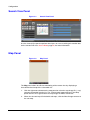
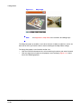
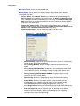
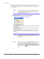
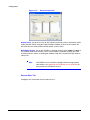
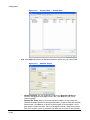
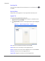
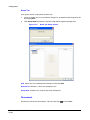
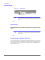
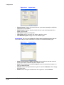
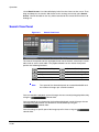
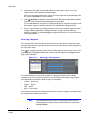
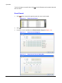
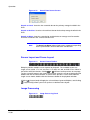
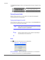
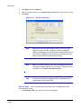
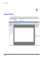
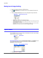
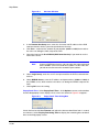
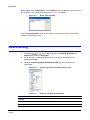
Map Editor
Name Table Select Name Table… in the Option menu to display the name instead of
the IP address of the DVR on the Map panel. Figure C-8 appears.
Figure C-8
Name Table Window
Click the Display Name field of each IP address and enter the name of the DVR to
display on the popup screen.
Device Setting
1.
Selecting
,
, or
on the toolbar displays the Camera, AlarmOut and
AlarmIn tabs under the Image Bar.
2.
Select the icons, and drag and drop them at the desired locations on the
background image.
3.
Go to the Property [Camera/AlarmOut/AlarmIn] tab and set the device
information.
Property
Figure C-9
Property [Camera/AlarmOut/AlarmIn] Tab
Table C-1
Property Tab Device Information
Description
General
Name
Enter a device name.
Description
Enter a description of the device.
Document 800-05056 Rev C
11/09
95
Map Editor
Table C-1
Property Tab Device Information
Property
Description
Site Information
Select a proper site for the device in the list, and the Equipment
fields (User, Password, IP Address and Port) are filled
automatically with the information set in Site Information Setting....
Image
Select an image of a device.
Ratio
Adjust the size of the device image.
X Coordinates / Y
Coordinates
Adjust the position of the device image by clicking each field and
changing the numbers.
Horizontal / Vertical Adjust the size of the device image by clicking each field and
changing the numbers.
Popup Camera
If the selected device is an alarm-in device, you can associate a
camera with the sensor by entering the camera name. The camera
name you enter should be the same as the camera name entered
under the Property [Camera] tab. The Map panel pops up another
screen and displays images of the camera associated with the
sensor on the popup screen when an alarm-in event occurs.
Equipment
96
IP Address / User /
Password / Port
Each field is filled in automatically with the information (user ID,
password, and port number) set in Site Information Setting..., or
you can enter it manually.
Device No.
Set the device number (1 ~ 32) for each device. If the selected
device is a camera, Device No. changes to Camera No.
DVRNS Use
Select Yes to use DVR Name Service, and the DVRNS field appears.
Enter the IP address (or domain name) and the port number of the
DVRNS server, and the name of the DVR registered on the DVRNS
server.
Note
You should not select numbers that are not supported for
devices on the remote DVR when selecting Device No.
Otherwise, the map cannot detect the device and it displays the
device status as Unplugged. For example, the device number
should be from 1 to 16 when the device is connected to a
16-channel DVR.
Note
If you set the IP address and port number of the DVRNS server in
Site Information Setting…, the DVRNS fields are filled with the
information automatically.
Map Editor
Note
4.
The DVRNS function is supported only with the devices
associated with a DVR providing the DVRNS (DVR Name
Service) function.
Go to the Event [Camera/AlarmOut/AlarmIn] tab and set the option for the
devices.
Figure C-10
•
Event [Camera]: Selecting an event from a drop-down list and checking the
Watch View Popup box sets the Map panel to pop up another screen when
an event occurs. Selecting Click from a drop-down list and checking the
Watch View Popup box pops up another screen by clicking the mouse
button on the camera icon on the Map panel regardless of event detection.
Figure C-11
•
Event [AlarmOut] Tab
Event [AlarmOut]: Checking the Switch on/off box controls the alarm-out
remotely by clicking the alarm-out icon on the Map panel.
Figure C-12
•
Event [Camera] Tab
Event [AlarmIn] Tab
Event [AlarmIn]: Selecting Alarm-in Event from the drop-down list and
checking the Watch View Popup box sets the Map panel to pop up another
screen when an alarm-in event occurs. Selecting Click from a drop-down list
and checking the Watch View Popup box pops up another screen by
clicking the mouse button on the alarm-in icon on the Map panel regardless
of event detection.
Note
Document 800-05056 Rev C
11/09
The popup camera should be associated with the alarm in
device to use the popup function. See Popup Camera, Device
Setting on page 95 for the popup camera association.
97
Map Editor
Link Setting
1.
Click
(Link) on the toolbar and place it on the screen linked with a sub-map.
2.
The Link Map
box appears. Select the individual link boxes by using the
Ctrl key on the keyboard, and then adjust the size and position of the link box
using a mouse, a keyboard or the icons shown below.
Interval adjustment: Equalizes the distance between three or more
selected boxes.
Size adjustment: Equalizes the size of two or more selected boxes.
Clicking the arrow keys while holding the Shift key on the keyboard
changes the size of the selected boxes.
Position adjustment: Arranges two or more selected boxes towards one
direction or towards the center. Clicking the arrow keys while holding the
Ctrl key on a keyboard changes the position of selected boxes.
Cut, Copy, Paste: Cuts, copies or pastes the link box.
3.
Go to the Property [Link] tab and set the properties of the selected link box.
Figure C-13
Property [Link] Tab
Table C-2
Property Tab Device Information
Property
Description
Name
Enter a name for the link box.
Image
Double-click the field and select an image to insert in the link box.
Link Document
Double-click the field and select a map to be linked with the link box.
Ratio
Adjust the image size within the link box.
X Coordinates / Y
Coordinates
Adjust the position of the link box on the screen by clicking each field
and changing the numbers.
Horizontal / Vertical Adjust the link box size by clicking each field and changing the
numbers.
Text Show
4.
98
Click
Select Yes to display the name of the link box on the selected image.
(Save) on the toolbar to save the map.
Map Editor
You can monitor the remote sites by using the map. See Map Panel on page 28 for more
information.
Document 800-05056 Rev C
11/09
99
Map Editor
100
Honeywell Security Group (Head Office)
2700 Blankenbaker Pkwy, Suite 150
Louisville, KY 40299, USA
www.honeywellvideo.com
℡ +1.800.796.2288
Honeywell Security Group Northern Europe
Ampèrestraat 41
1446 TR Purmerend, The Netherlands
www.honeywell.com/security/nl
℡ +31.299.410.200
Honeywell Security Group Europe/South Africa
Aston Fields Road, Whitehouse Ind Est
Runcorn, Cheshire, WA7 3DL, UK
www.honeywell.com/security/uk
℡ +44.01928.754028
Honeywell Security Group Deutschland
Johannes-Mauthe-Straße 14
D-72458 Albstadt, Germany
www.honeywell.com/security/de
℡ +49.74 31.8 01.0
Honeywell Security Group Caribbean/Latin America
9315 NW 112th Ave.
Miami, FL 33178, USA
www.honeywellvideo.com
℡ +1.305.805.8188
Honeywell Security Group Pacific
Level 3, 2 Richardson Place
North Ryde, NSW 2113, Australia
www.honeywellsecurity.com.au
℡ +61.2.9353.7000
Honeywell Security Group Asia
35F Tower A, City Center, 100 Zun Yi Road
Shanghai 200051, China
www.asia.security.honeywell.com
℡ +86 21.5257.4568
Honeywell Security Group Middle East/N. Africa
Post Office Box 18530
LOB Building 08, Office 199
Jebel Ali, Dubai, United Arab Emirates
www.honeywell.com/security/me
℡ +971.04.881.5506
Honeywell Security Group France
Immeuble Lavoisier
Parc de Haute Technologie
3-7 rue Georges Besse
92160 Antony, France
www.honeywell.com/security/fr
℡ +33.(0).1.40.96.20.50
Honeywell Security Group Italia SpA
Via della Resistenza 53/59
20090 Buccinasco
Milan, Italy
www.honeywell.com/security/it
℡ +39.02.4888.051
Honeywell Security Group España
Mijancas 1. 3a planta
P. Ind. Las Mercedes
28022 Madrid, Spain
www.honeywell.com/security/es
℡ +34.902.667.800
www.honeywellvideo.com
+1.800.796.CCTV (North America only)
[email protected]
Document 800-05056 – Rev C – 11/09
© 2009 Honeywell International Inc. All rights reserved. No part of this publication may be reproduced by any means
without written permission from Honeywell. The information in this publication is believed to be accurate in all respects.
However, Honeywell cannot assume responsibility for any consequences resulting from the use thereof. The information
contained herein is subject to change without notice. Revisions or new editions to this publication may be issued to
incorporate such changes.