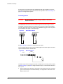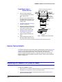
1
EQUIP™ Series
Indoor Fixed Mini Dome
Network Camera
NTSC / PAL
HD3MDIP
HD3MDIPX
User Guide
Document 800-04132V1 – Rev A – 01/10
Revisions
Issue
Date
Revisions
A
09/09
New document for HD3MDIP/X release. Generally describes the functionality in the
firmware of the HD3MDIP/X camera.
V1 A
01/10
New version number and release date.
2
HD3MDIP/X Network Camera Reference Guide
Contents
Figures. . . . . . . . . . . . . . . . . . . . . . . . . . . . . . . . . . . . . . . . . . . . . . . . . . 5
Tables . . . . . . . . . . . . . . . . . . . . . . . . . . . . . . . . . . . . . . . . . . . . . . . . . . 7
About This Document . . . . . . . . . . . . . . . . . . . . . . . .
Overview of Contents. . . . . . . . . . . . . . . . . . . . . . .
Cautions and Warnings . . . . . . . . . . . . . . . . . . . . .
FCC Compliance Statement . . . . . . . . . . . . . . . . . . .
Manufacturer’s Declaration of Conformance. . . . . . . . . . .
North America. . . . . . . . . . . . . . . . . . . . . .
Europe . . . . . . . . . . . . . . . . . . . . . . . . .
Warranty and Service. . . . . . . . . . . . . . . . . . . . . . .
1
.
.
.
.
.
.
.
.
.
.
.
.
.
.
.
.
.
.
.
.
.
.
.
.
.
.
.
.
.
.
.
.
.
.
.
.
.
.
.
.
.
.
.
.
.
.
.
.
.
.
.
.
.
.
.
.
.
.
.
.
.
.
.
.
.
.
.
.
.
.
.
.
.
.
.
.
.
.
.
.
.
.
.
.
.
.
.
.
.
.
.
.
.
.
.
.
.
.
.
.
.
.
.
.
.
.
.
.
.
.
.
.
.
.
.
.
.
.
.
.
.
.
.
.
.
.
.
.
. . . . .9
. . . . . 9
. . . . 10
. . . . 10
. . . . 11
. . . . . 11
. . . . . 11
. . . . 11
Introduction . . . . . . . . . . . . . . . . . . . . . . . . . . . . . . . . . . . . . . . . . . . . . . 13
Features . . . . . . . . . . . . . . . . . . . . . . . . . . . . . . . . . . . . . . . . . . . . . . . . . 13
2
Installation and Setup. . . . . . . . . . . . . . . . . . . . . . . . . . . . . . . . . . . . . . . . . 15
Before You Begin . . . . . . . . . . . . . .
Unpack Everything . . . . . . . .
Equipment Required . . . . . . .
Overview of Installation Procedure . . . . .
Camera Components and Functions . . .
Camera Installation . . . . . . . . . . . . .
Preparing the Camera . . . . . .
Preparing the Mounting Surface .
Connecting the Wires . . . . . . .
Mounting the Camera. . . . . . .
Restore Factory Defaults . . . . .
Adjusting the Camera FOV (Field of View) .
Adjusting the Lens Focus. . . . .
Securing the Enclosure Cover . . . . . . .
3
.
.
.
.
.
.
.
.
.
.
.
.
.
.
.
.
.
.
.
.
.
.
.
.
.
.
.
.
.
.
.
.
.
.
.
.
.
.
.
.
.
.
.
.
.
.
.
.
.
.
.
.
.
.
.
.
.
.
.
.
.
.
.
.
.
.
.
.
.
.
.
.
.
.
.
.
.
.
.
.
.
.
.
.
.
.
.
.
.
.
.
.
.
.
.
.
.
.
.
.
.
.
.
.
.
.
.
.
.
.
.
.
.
.
.
.
.
.
.
.
.
.
.
.
.
.
.
.
.
.
.
.
.
.
.
.
.
.
.
.
.
.
.
.
.
.
.
.
.
.
.
.
.
.
.
.
.
.
.
.
.
.
.
.
.
.
.
.
.
.
.
.
.
.
.
.
.
.
.
.
.
.
.
.
.
.
.
.
.
.
.
.
.
.
.
.
.
.
.
.
.
.
.
.
.
.
.
.
.
.
.
.
.
.
.
.
.
.
.
.
.
.
.
.
.
.
.
.
.
.
.
.
.
.
.
.
.
.
.
.
.
.
.
.
.
.
.
.
.
.
.
.
.
.
.
.
.
.
.
.
.
.
.
.
.
.
.
.
.
.
.
.
.
.
.
.
.
.
.
.
.
.
.
.
.
.
.
.
.
.
.
.
.
.
.
.
.
.
.
.
.
.
.
.
.
.
.
.
.
.
.
.
.
.
.
.
.
.
.
.
.
.
.
.
.
.
.
.
.
.
.
.
.
.
.
.
.
.
.
.
.
.
.
.
.
.
.
.
.
.
.
.
.
.
.
.
.
.
.
.
.
.
.
.
.
.
.
.
.
.
.
.
.
.
.
.
.
.
.
.
.
.
.
.
.
.
.
.
.
.
.
.
.
.
.
.
.
.
.
.
.
.
.
.
.
.
.
.
.
.
.
.
.
.
.
.
.
.
.
.
.
.
.
.
.
.
.
.
.
.
.
.
.
.
. 15
. 15
. 16
. 16
. 17
. 18
. 18
. 18
. 19
. 24
. 25
. 25
. 26
. 27
Installing the Honeywell IP Utility and HD3MDIP/X Web-Client Software . . . . . . . . . . . . . 29
About the Honeywell IP Utility and Web-Client. . . . . . . . . . . . . . . .
About the Honeywell IP Utility . . . . . . . . . . . . . . . . . . .
About the Web-Client . . . . . . . . . . . . . . . . . . . . . . . .
User Profiles: Honeywell IP Utility and Web-Client . . . . . . . . .
Step 1: Confirm Your System Requirements. . . . . . . . . . . . . . . . .
Step 2: Install the Honeywell IP Utility Software . . . . . . . . . . . . . . .
Downloading the EQUIP Series Installation Guides . . . . . . . .
Step 3: Log Onto the IP Utility and Discover Network Devices . . . . . . .
Step 4: Connect to a Device and Configure Network Settings . . . . . . .
Connecting to or Disconnecting From Devices . . . . . . . . . .
Configuring the IP Network Settings Automatically or Manually . .
Interfacing with the EQUIP Device Via a Network Video Recorder
Document 800-04132V1 – Rev A – 01/10
.
.
.
.
.
.
.
.
.
.
.
.
.
.
.
.
.
.
.
.
.
.
.
.
.
.
.
.
.
.
.
.
.
.
.
.
.
.
.
.
.
.
.
.
.
.
.
.
.
.
.
.
.
.
.
.
.
.
.
.
.
.
.
.
.
.
.
.
.
.
.
.
.
.
.
.
.
.
.
.
.
.
.
.
.
.
.
.
.
.
.
.
.
.
.
.
.
.
.
.
.
.
.
.
.
.
.
.
.
.
.
.
.
.
.
.
.
.
.
.
.
.
.
.
.
.
.
.
.
.
.
.
.
.
.
.
.
.
.
.
.
.
.
.
.
.
.
.
.
.
.
.
.
.
.
.
.
.
.
.
.
.
.
.
.
.
.
.
. 29
. 29
. 30
. 30
. 31
. 32
. 32
. 33
. 34
. 35
. 35
. 38
3
Contents
Step 5: Launch the Web-Client to View Live Video . . . . . . . . . .
Uninstalling IP Utility, Bonjour or the ActiveX Plug-in Software . . . .
Uninstalling IP Utility Using the Start Menu . . . . . . . . .
Uninstalling IP Utility or IP ActiveX Using the Control Panel .
4
.
.
.
.
.
.
.
.
.
.
.
.
.
.
.
.
.
.
.
.
.
.
.
.
.
.
.
.
.
.
.
.
.
.
.
.
.
.
.
.
.
.
.
.
.
.
.
.
.
.
.
.
.
.
.
.
.
.
.
.
.
.
.
.
.
.
.
.
. 38
. 40
. 41
. 41
IP Camera Web-Client . . . . . . . . . . . . . . . . . . . . . . . . . . . . . . . . . . . . . . . . 43
Overview . . . . . . . . . . . . . . . . . . . . . . . . . . . . . .
User Profiles . . . . . . . . . . . . . . . . . . . . . . .
Logging On and Off the HD3MDIP/X IP Web-Client . . . . . . . .
Launching the Web-Client from IP Utility . . . . . . . . .
Logging Onto the Web-Client from Internet Explorer . .
Logging Out of the Web-Client . . . . . . . . . . . . . .
Navigating the User Interface . . . . . . . . . . . . . . . . . . .
Live View . . . . . . . . . . . . . . . . . . . . . . . . . . . . . .
Device Settings . . . . . . . . . . . . . . . . . . . . . . . . . . .
IP and Firmware Settings on the Device Information Tab
Compression Settings . . . . . . . . . . . . . . . . . . . . . . .
Video Codec Settings Tab . . . . . . . . . . . . . . . .
Statistics: Received Bit Rate and Frame Rate . . . . . .
Camera Setup . . . . . . . . . . . . . . . . . . . . . . . . . . .
Auto Exposure . . . . . . . . . . . . . . . . . . . . . .
White Balance. . . . . . . . . . . . . . . . . . . . . . .
Video Analytics . . . . . . . . . . . . . . . . . . . . . . . . . . .
Sabotage Detection. . . . . . . . . . . . . . . . . . . .
Configuring Video Motion Detection . . . . . . . . . . .
Alarm and Audio . . . . . . . . . . . . . . . . . . . . . . . . . .
Alarm Settings . . . . . . . . . . . . . . . . . . . . . .
Audio Settings . . . . . . . . . . . . . . . . . . . . . .
.
.
.
.
.
.
.
.
.
.
.
.
.
.
.
.
.
.
.
.
.
.
.
.
.
.
.
.
.
.
.
.
.
.
.
.
.
.
.
.
.
.
.
.
.
.
.
.
.
.
.
.
.
.
.
.
.
.
.
.
.
.
.
.
.
.
.
.
.
.
.
.
.
.
.
.
.
.
.
.
.
.
.
.
.
.
.
.
.
.
.
.
.
.
.
.
.
.
.
.
.
.
.
.
.
.
.
.
.
.
.
.
.
.
.
.
.
.
.
.
.
.
.
.
.
.
.
.
.
.
.
.
.
.
.
.
.
.
.
.
.
.
.
.
.
.
.
.
.
.
.
.
.
.
.
.
.
.
.
.
.
.
.
.
.
.
.
.
.
.
.
.
.
.
.
.
.
.
.
.
.
.
.
.
.
.
.
.
.
.
.
.
.
.
.
.
.
.
.
.
.
.
.
.
.
.
.
.
.
.
.
.
.
.
.
.
.
.
.
.
.
.
.
.
.
.
.
.
.
.
.
.
.
.
.
.
.
.
.
.
.
.
.
.
.
.
.
.
.
.
.
.
.
.
.
.
.
.
.
.
.
.
.
.
.
.
.
.
.
.
.
.
.
.
.
.
.
.
.
.
.
.
.
.
.
.
.
.
.
.
.
.
.
.
.
.
.
.
.
.
.
.
.
.
.
.
.
.
.
.
.
.
.
.
.
.
.
.
.
.
.
.
.
.
.
.
.
.
.
.
.
.
.
.
.
.
.
.
.
.
.
.
.
.
.
.
.
.
.
.
.
.
.
.
.
.
.
.
.
.
.
.
.
.
.
.
.
.
.
.
.
.
.
.
.
.
.
.
.
.
.
.
.
.
.
.
.
.
.
.
.
.
.
.
.
.
.
.
.
.
.
.
.
.
.
.
.
.
.
.
.
.
.
.
.
.
.
.
. 43
. 44
. 44
. 45
. 46
. 46
. 47
. 49
. 49
. 50
. 51
. 52
. 54
. 55
. 55
. 57
. 57
. 58
. 61
. 62
. 62
. 63
Appendix A
Mounting Template. . . . . . . . . . . . . . . . . . . . . . . . . . . . . . . . . . . . 65
Appendix B
Troubleshooting . . . . . . . . . . . . . . . . . . . . . . . . . . . . . . . . . . . . . 67
Technical Support . . . . . . . . . . . . . . . . . . . . .
Problem: Lens Out of Optical Focus . . . . . . . . . . . .
Problem: Live View Does Not Display the Expected Video
Problem: Cannot Connect to a Device . . . . . . . . . . .
.
.
.
.
.
.
.
.
.
.
.
.
.
.
.
.
.
.
.
.
.
.
.
.
.
.
.
.
.
.
.
.
.
.
.
.
.
.
.
.
.
.
.
.
.
.
.
.
.
.
.
.
.
.
.
.
.
.
.
.
.
.
.
.
.
.
.
.
.
.
.
.
.
.
.
.
.
.
.
.
.
.
.
.
.
.
.
.
.
.
.
.
. 67
. 67
. 68
. 68
Appendix C
Specifications . . . . . . . . . . . . . . . . . . . . . . . . . . . . . . . . . . . . . . 69
Appendix D
Glossary . . . . . . . . . . . . . . . . . . . . . . . . . . . . . . . . . . . . . . . . . 73
Index . . . . . . . . . . . . . . . . . . . . . . . . . . . . . . . . . . . . . . . . . . . . . . . . . . . . . 75
4
HD3MDIP/X Network Camera Reference Guide
Figures
Figure 2-1
HD3MDIP/X Camera Components . . . . . . . . . . . . . . . . . . . . . . . . . . . . . . 17
Figure 2-2
Mounting Template . . . . . . . . . . . . . . . . . . . . . . . . . . . . . . . . . . . . . . 18
Figure 2-3
Audio and Alarm PINs . . . . . . . . . . . . . . . . . . . . . . . . . . . . . . . . . . . . . 19
Figure 2-4
Normal Alarm States . . . . . . . . . . . . . . . . . . . . . . . . . . . . . . . . . . . . . . 20
Figure 2-5
Alarm Connection . . . . . . . . . . . . . . . . . . . . . . . . . . . . . . . . . . . . . . . 20
Figure 2-6
Camera and Cables . . . . . . . . . . . . . . . . . . . . . . . . . . . . . . . . . . . . . . 22
Figure 2-7
Wiring Connection Shown on Board . . . . . . . . . . . . . . . . . . . . . . . . . . . . . 22
Figure 2-8
Gimbal Adjustment . . . . . . . . . . . . . . . . . . . . . . . . . . . . . . . . . . . . . . 26
Figure 2-9
Installing the Enclosure Cover . . . . . . . . . . . . . . . . . . . . . . . . . . . . . . . . . 27
Figure 3-1
Accessing Your Installation Documents . . . . . . . . . . . . . . . . . . . . . . . . . . . . 32
Figure 3-2
Honeywell IP Utility Log On Window . . . . . . . . . . . . . . . . . . . . . . . . . . . . . 33
Figure 3-3
Honeywell IP Utility User Interface. . . . . . . . . . . . . . . . . . . . . . . . . . . . . . . 34
Figure 3-4
Set the IP Network Settings Automatically or Manually . . . . . . . . . . . . . . . . . . . . 36
Figure 3-5
ActiveX Prompt. . . . . . . . . . . . . . . . . . . . . . . . . . . . . . . . . . . . . . . . . 39
Figure 3-6
Web-Client Interface After Logging On . . . . . . . . . . . . . . . . . . . . . . . . . . . . 40
Figure 4-1
Launching the HD3MDIP/X Web-Client from IP Utility . . . . . . . . . . . . . . . . . . . . 45
Figure 4-2
Web-Client Window Layout: Administrator Log On . . . . . . . . . . . . . . . . . . . . . . 47
Figure 4-3
Web-Client: Administrator User . . . . . . . . . . . . . . . . . . . . . . . . . . . . . . . . 48
Figure 4-4
Web-Client: Guest User . . . . . . . . . . . . . . . . . . . . . . . . . . . . . . . . . . . . 49
Figure 4-5
Device Settings . . . . . . . . . . . . . . . . . . . . . . . . . . . . . . . . . . . . . . . . 50
Figure 4-6
IP and Firmware Settings: Device Information Tab . . . . . . . . . . . . . . . . . . . . . . 51
Figure 4-7
Compressions Settings Tab: Primary Stream . . . . . . . . . . . . . . . . . . . . . . . . . 52
Figure 4-8
Video Codec Settings Tab Available Functions
Figure 4-9
Video Codec Settings, Quality Priority Selected . . . . . . . . . . . . . . . . . . . . . . . 54
Figure 4-10
Camera Setup . . . . . . . . . . . . . . . . . . . . . . . . . . . . . . . . . . . . . . . . . 55
. . . . . . . . . . . . . . . . . . . . . . . 52
Figure 4-11
Video Analytics Tab . . . . . . . . . . . . . . . . . . . . . . . . . . . . . . . . . . . . . . 58
Figure 4-12
Tamper Detection Settings on the Video Analytics Tab. . . . . . . . . . . . . . . . . . . . 58
Figure 4-13
Video Analytics Alarm Message . . . . . . . . . . . . . . . . . . . . . . . . . . . . . . . . 59
Figure 4-14
Video Analytics: Defining a Region . . . . . . . . . . . . . . . . . . . . . . . . . . . . . . 62
Figure 4-15
Audio Settings . . . . . . . . . . . . . . . . . . . . . . . . . . . . . . . . . . . . . . . . . 63
Figure B-1
Limited or No Connection Message . . . . . . . . . . . . . . . . . . . . . . . . . . . . . . 68
Figure C-1
HD3MDIP/X Side View with Dimensions . . . . . . . . . . . . . . . . . . . . . . . . . . . 70
Figure C-2
HD3MDIP/X Side View Dimensions without Skirt . . . . . . . . . . . . . . . . . . . . . . . 71
Figure C-3
HD3MDIP/X Side View Dimensions with Adapter Plate . . . . . . . . . . . . . . . . . . . . 71
Figure C-4
HD3MDIP/X Bottom View with Dimensions . . . . . . . . . . . . . . . . . . . . . . . . . . 71
Document 800-04132V1 – Rev A – 01/10
5
Figures
6
HD3MDIP/X Network Camera Reference Guide
Tables
Table 1-1
Fixed Mini Dome Network Camera Model Numbers . . . . . . . . . . . . . . . . . . . . . . 13
Table 2-1
Audio and Alarm Connector PIN Definitions . . . . . . . . . . . . . . . . . . . . . . . . . . 19
Table 3-1
User Profiles for Honeywell IP Utility and the Web-Client . . . . . . . . . . . . . . . . . . . 30
Table 3-2
PC Minimum System Requirements . . . . . . . . . . . . . . . . . . . . . . . . . . . . . . 31
Table 3-3
Items Installed On Your System . . . . . . . . . . . . . . . . . . . . . . . . . . . . . . . . 31
Table 3-4
IP Network Device Setting Options . . . . . . . . . . . . . . . . . . . . . . . . . . . . . . . 36
Table 4-1
User Roles and Privileges . . . . . . . . . . . . . . . . . . . . . . . . . . . . . . . . . . . 44
Table 4-2
Tabs/Views in the Web-Client Application . . . . . . . . . . . . . . . . . . . . . . . . . . . 48
Table 4-3
Compression Settings . . . . . . . . . . . . . . . . . . . . . . . . . . . . . . . . . . . . . 53
Table 4-4
Auto Exposure Settings. . . . . . . . . . . . . . . . . . . . . . . . . . . . . . . . . . . . . 56
Table 4-5
White Balance Settings . . . . . . . . . . . . . . . . . . . . . . . . . . . . . . . . . . . . . 57
Table 4-6
Blur Threshold Values . . . . . . . . . . . . . . . . . . . . . . . . . . . . . . . . . . . . . 59
Table 4-7
Blinding Threshold Values . . . . . . . . . . . . . . . . . . . . . . . . . . . . . . . . . . . 60
Table 4-8
Scene Change Threshold Values . . . . . . . . . . . . . . . . . . . . . . . . . . . . . . . 61
Document 800-04132V1 – Rev A – 01/10
7
Tables
8
HD3MDIP/X Network Camera Reference Guide
About This Document
This document introduces the Honeywell HD3MDIP/X True Day/Night Indoor Network
Camera. It covers how to install and operate the HD3MDIP/X in a network environment.
This document is intended for system installers, administrators, and operators.
Overview of Contents
This document contains the following chapters and appendixes:
•
•
•
•
•
•
•
•
•
Document 800-04132V1 Rev A
01/10
Chapter 1, Introduction, introduces the Honeywell HD3MDIP/X Network Camera and
gives a functional overview of its components.
Chapter 2, Installation and Setup, provides procedures for installing cameras,
adjusting the lens, and setting up a network camera environment.
Chapter 3, Installing the Honeywell IP Utility and HD3MDIP/X Web-Client Software,
describes how to install the Honeywell IP Utility and set up administrator privileges.
Chapter 4, IP Camera Web-Client, describes how to use the Web-Client application
to view video and configure the available settings for the network camera.
Appendix A, Mounting Template, provides a mounting template for the HD3MDIP/X
camera.
Appendix B, Troubleshooting, lists common problems encountered when setting up
the network camera.
Appendix C, Specifications, provides specifications for the HD3MDIP/X camera.
Appendix D, Glossary, explains terms and initializations used in this guide.
The Index provides quick access to commonly searched terms.
9
Cautions and Warnings
RISK OF
ELECTRIC SHOCK
DO NOT OPEN
THIS SYMBOL INDICATES
THAT DANGEROUS VOLTAGE
CONSTITUTING A RISK OF
ELECTRIC SHOCK IS
PRESENT WITHIN THE UNIT.
CAUTION: TO REDUCE THE RISK OF
ELECTRIC SHOCK, DO NOT REMOVE
THE COVER. NO USER-SERVICEABLE
PARTS INSIDE. REFER SERVICING TO
QUALIFIED SERVICE PERSONNEL.
THIS SYMBOL INDICATES
THAT IMPORTANT OPERATING
AND MAINTENANCE
INSTRUCTIONS ACCOMPANY
THIS UNIT.
CAUTION
Installation and servicing should be performed only by qualified and experienced
technicians to conform to all local codes and to maintain your warranty.
WARNING!
24 VAC models require the use of CSA Certified/UL Listed
Class 2 power adapters to ensure compliance with
electrical safety standards. Power over Ethernet (PoE)
should meet the IEEE 802.3 af PoE standard.
WEEE (Waste Electrical and Electronic Equipment). Correct disposal of this
product (applicable in the European Union and other European countries with
separate collection systems). This product should be disposed of, at the end of
its useful life, as per applicable local laws, regulations, and procedures.
Caution
When powering the camera from 24 VAC, a UPS source should
be considered to ensure satisfactory performance.
FCC Compliance Statement
Information to the User: This equipment has been tested and found to comply with the
limits for a Class B digital device. Pursuant to Part 15B of the FCC Rules, these limits are
designed to provide reasonable protection against harmful interference in a residential
installation. This equipment generates, uses, and can radiate radio frequency energy and,
if not installed and used in accordance with the instruction manual, may cause harmful
interference to radio communications. However, there is no guarantee that interference
will not occur in a particular installation.
10
HD3MDIP/X Network Camera Reference Guide
If this equipment does cause harmful interference to radio or television reception, which
can be determined by turning the equipment off and on, the user is encouraged to try to
correct the interference. For example, try reorienting or relocating the receiving antenna,
increasing the separation between the equipment and receiver, or connecting the
equipment to an outlet on a different circuit.
Caution
Changes or modifications not expressly approved by the party
responsible for compliance could void the user’s authority to
operate the equipment.
This Class B digital apparatus complies with Canadian ICES-003.
Manufacturer’s Declaration of Conformance
North America
The equipment supplied with this guide conforms to UL 60950-1 and CSA C22.2 No.
60950-1.
Europe
The manufacturer declares that the equipment supplied with this guide is compliant with
the essential protection requirements of the EMC directive 2004/108/EC and the Low
Voltage Directive LVD 20006/95/EC, conforming to the requirements of standards EN
55022 for emissions, EN 50024 for immunity, and EN 60950 for Electrical Equipment
safety.
Warranty and Service
Subject to the terms and conditions listed on the Product warranty, during the warranty
period Honeywell will repair or replace, at its sole option, free of charge, any defective
products returned prepaid.
In the event you have a problem with any Honeywell product, please call Customer
Service at 1.800.796.CCTV for assistance or to request a Return Merchandise
Authorization (RMA) number.
Be sure to have the model number, serial number, and the nature of the problem available
for the technical service representative.
Document 800-04132V1 Rev A
01/10
11
Prior authorization must be obtained for all returns, exchanges, or credits. Items shipped
to Honeywell without a clearly identified Return Merchandise Authorization (RMA)
number may be refused.
12
1
Introduction
Honeywell HD3MDIP/X color network cameras provide high picture quality remote video
surveillance over a network connection. See Table 1-1 for descriptions of the camera
models.
Table 1-1
Fixed Mini Dome Network Camera Model Numbers
Model number
Description
HD3MDIP
True Day/Night 720p, 3.3 – 12 mm VFAI Lens NTSC
HD3MDIPX
True Day/Night 720p, 3.3 – 12 mm VFAI Lens PAL
Features
The Honeywell HD3MDIP/X color network camera features:
•
•
•
•
•
•
•
•
•
•
•
•
•
•
•
•
Document 800-04132V1 Rev A
01/10
HD, SVGA, VGA, QVGA resolutions
1/4" color CMOS progressive scan sensor
Moveable Infrared (IR) cut filter ensures excellent low light performance
Camera Sabotage Detection
Video Motion Detection
MPEG-4 and MJPEG compression
Dual digital video streams simultaneously, independently configurable
Remote firmware updates
Supports both Dynamic and Static IP address assignment
Multiple levels of password protected remote access prevents unauthorized users
from altering system settings
Includes advanced IP locator software to make system setup easy
Web server for remote setup of camera video and network parameters
24 VAC or PoE IEEE 802.3af choice of power inputs
Supports input and output alarm contacts
Supports bi-directional audio
Local video out – aim and focus
13
Introduction
14
2
Installation and Setup
This chapter describes how to:
•
•
•
Mount the camera
Adjust the camera for the clearest image
Set up the camera in a network system
Before You Begin
Please carefully read this guide before you install
the HD3MDIP/X network camera.
Keep this guide for future reference.
Before installing the camera, Honeywell recommends that you check
www.honeywellvideo.com/products/cameras/ to find your camera and download the
latest manuals and software updates.
Unpack Everything
Check that the items received match those listed on the order form and packing slip. The
HD3MDIP/X packing box should include, in addition to a Quick Install Guide:
•
•
•
•
•
•
•
Document 800-04132V1 Rev A
01/10
One fully-assembled HD3MDIP/X camera, including factory-installed BNC
connector for local video out aim and focus
One adapter plate
One HD3MDIP/X hardware kit that includes mounting screws and screw caps
One BNC cable for local video out - aim and focus
One mounting template
One product warranty
One CD containing the software and this User Guide
15
Installation and Setup
If any parts are missing or damaged, contact the dealer from which you purchased your
camera or call Honeywell Customer Service (see Warranty and Service).
Equipment Required
The following tools might help you to complete the installation:
•
•
•
Drill
Screwdrivers
Wire cutters
Overview of Installation Procedure
Note
Please familiarize yourself with the installation procedure and complete each
step in the exact sequence given.
The initial installation of an HD3MDIP/X camera consists of the following steps:
16
Step
See …
1
Preparation
page 18
2
Connect the wiring.
page 21
Mount the camera.
page 24
3
Adjust the camera angle, position, and
focus for optimum image.
page 25
4
Secure the enclosure cover.
page 27
5
Program the camera.
page 55
HD3MDIP/X Network Camera Reference Guide
Camera Components and Functions
The HD3MDIP/X Network Camera consists of a fully-integrated enclosure with camera and
lens. The wiring can be completely concealed to reduce the risk of tampering.
Figure 2-1
HD3MDIP/X Camera Components
Cover plate
Flush Mount
Surface Mount
Back box
(not supplied)
Skirt
Adapter plate
Base
Camera
Interface board
Gimbal base
Gimbal assembly
Turret (bubble insert)
Bubble
Document 800-04132V1 Rev A
01/10
17
Installation and Setup
Camera Installation
Preparing the Camera
1.
Rotate the bubble counterclockwise until it
disconnects.
2.
Pull the turret to remove it.
3.
Rotate the camera counterclockwise until it
disconnects from the skirt.
4.
Set aside the bubble, turret, and camera.
Skirt
Camera
Turret
Bubble
Preparing the Mounting Surface
1.
Mark the mounting surface for screw holes and wire access hole.
•
•
Use the mounting template if you are surface mounting your camera. See
Mounting Template on page 65
Use the flush mount adapter plate as a template if you are flush mounting your
camera.
Figure 2-2
Mounting Template
Drill these holes for the
mounting screws.
Cut this hole, then pull the
power, audio, and alarm
wires through it.
18
HD3MDIP/X Network Camera Reference Guide
2.
Pre-drill the holes as indicated on the template, using the recommended hole size for
the screws being used.
Note
Other fasteners (preferably stainless steel) can be used, provided they are not
larger than the screw holes on the mounting template.
Connecting the Wires
Connecting Audio and Alarms
1.
Pull the wires through the ceiling or wall hole until you have at least 4 inches of wire.
2.
Remove the green connector strip (see Figure 2-6 on page 22) from the camera base
and make all the necessary alarm and audio connections.
3.
Connect a twisted pair (UTP) cable from each peripheral alarm contact to each alarm
input on the terminal block.
Figure 2-3
Audio and Alarm PINs
1
Power
Table 2-1
2
3
4
5
6
7
8
Audio and Alarm Connector PIN Definitions
PIN
Definition
1
Audio In +
2
Audio In -
3
Audio Out +
4
Audio Out -
5
Alarm In +
6
Alarm In -
7
Alarm Out +
8
Alarm Out -
Connecting Audio
The network camera supports bi-directional audio. There are two supported voice band
channels that function in full duplex mode. The camera can transmit audio from the camera
to the client (PC) using any audio source that provides an industry standard line level input
(see the terminal strip as depicted in Figure 2-6). The camera can also receive audio from
Document 800-04132V1 Rev A
01/10
19
Installation and Setup
the client (PC) and provide an industry standard line level output suitable to connect to
audio devices. Audio input and output have 600 Ohm impedance. See Audio Settings on
page 63 to configure audio options.
Connecting Alarms
WARNING!
Do not exceed the maximum rating of 12 VDC, 0.5 A on alarm
output connections.
The HD3MDIP/X network camera has one alarm input and one alarm output. Connect
mechanical or electrical switches to the alarm input connection to allow event-triggered
recording. When alarm inputs are configured, the HD3MDIP/X triggers an alarm only when
the normal alarm state (open or closed) changes.
Figure 2-4
Normal Alarm States
Normally opened
Normally closed
See Alarm Settings on page 62 to configure the alarm inputs.
Connect external devices such as sirens or flashing lights to the alarm output connector to
signal an activated alarm to camera users.
Figure 2-5
Audio
Alarm Connection
In
Alarm
Out
−
+
+
−
The alarm output can be configured to provide normally open or normally closed contacts
(see Alarm Settings on page 62 to configure the alarm output). Contacts will be rated for 12
VDC @ 0.5 A.
4.
20
Pull the cables through the back or side entries of the camera skirt, then connect the
green connector strip to the camera assembly. You might have to remove the cover
plate for flush mount.
HD3MDIP/X Network Camera Reference Guide
Connecting Power
WARNING!
Note
1.
The use of a CSA Certified/UL Listed Class 2 power supply is
required to ensure compliance with electrical safety
standards.
Check the power source from the external power supply before applying
power to the camera.
Connect the appropriate power supply for your installation:
•
•
Note
24 VAC power supply (proceed to step 2)
or
Power over Ethernet (IEEE 802.3af) 48 VDC power supply
If you are using PoE (802.3af), power will automatically be supplied to the
camera through the network cable.
2.
Connect to the power supply (see Figure 2-6 on page 22).
3.
Plug the power supply into an appropriate power source. The LED on the RJ45 jack
illuminates when the camera receives power. If it does not illuminate, check the
terminal block connections and the power source.
Note
Document 800-04132V1 Rev A
01/10
To ensure satisfactory performance, it is recommended that you use a UPS
source when connecting the camera to a 24 VAC power source.
21
Installation and Setup
Figure 2-6
Camera and Cables
RJ45 Ethernet network
connection (using 10Base T
or 100Base TX cable). See
Connecting to a Network
via an RJ-45 Ethernet
Connector, page 23)
Also for Power over
Ethernet (PoE 802.3af)
24 VAC power
Figure 2-7
Factory reset button
Local video out connector
(for aim and focus)
RJ45 Ethernet Connector
(see Connecting to a Network
via an RJ-45 Ethernet
Connector, page 23)
22
Wiring Connection Shown on Board
Connector Strip
Audio: Input/Output
Alarm: Input/Output
(see Connecting Alarms,
page 20)
HD3MDIP/X Network Camera Reference Guide
Caution
Installation must be performed by a qualified electrician. The power
wire size for the distance and the number of cameras must be
determined to maintain 24 VAC at each camera.
Connecting to a Video Monitor
The local video out (see Figure 2-7) is available as a test output and should be used as
needed during installation to position, aim, and focus the camera. Use the provided BNC
connector to connect the video from the camera to the video input connector on your video
monitor.
Connecting to a Network via an RJ-45 Ethernet Connector
The main video connection for your network camera will be made through your Ethernet
network connection. Connect the Ethernet connector on your camera to your network
using an Ethernet (10Base-T, 100Base-TX) cable.
Note
Document 800-04132V1 Rev A
01/10
You can connect your camera to a network or use any type of CAT5 cable to
connect it directly to a PC or laptop.
23
Installation and Setup
Mounting the Camera
Surface Mount
1.
24
Secure the skirt to the ceiling or wall using
the appropriate screws (supplied).
2.
Connect the wires (see Connecting the
Wires on page 19).
3.
Rotate and align the camera assembly
yellow label with the skirt yellow label.
4.
Secure the camera assembly to the skirt by
pushing it into the skirt, then twisting it
clockwise until it clicks securely in place.
Skirt
Screws
(supplied)
Camera
assembly
Turret
5.
Secure the camera assembly to the skirt by
twisting it clockwise until it clicks securely
in place.
6.
Adjust the camera’s field of view (see
Adjusting the Camera FOV (Field of View)
on page 25).
7.
Install the turret by clicking it into place.
8.
Install the bubble by placing it on the camera with the tabs to the left of the slots, then
turning it clockwise until the tabs click securely into place.
Bubble
HD3MDIP/X Network Camera Reference Guide
Flush Mount (with or
without 4S box)
1.
Use the screws (supplied) to
connect the adapter plate directly
to the ceiling or wall.
Or
Use your own screws to connect
the adapter plate to the 4S box (not
supplied) which is attached to the
ceiling or wall.
2.
Connect the wires (see Connecting
the Wires on page 19).
3.
Secure the camera assembly to the
adapter plate by twisting clockwise
until it clicks securely in place.
4.
Adjust the camera’s field of view
(see Adjusting the Camera FOV
(Field of View) on page 25).
5.
Install the turret by clicking it into
place.
6.
4S box (not supplied and optional)
Adapter plate
Screws
(supplied)
Screw caps
Camera
assembly
Turret
Bubble
Note Installation with 4S box shown
Install the bubble by placing it on
the camera with the tabs to the left
of the slots, then turning it clockwise until the tabs click securely into place.
Restore Factory Defaults
Your network camera has a Factory Reset switch located inside the camera (see Figure 2-6
on page 22). This switch restores your camera settings and passwords to their default
settings. Press and hold the Reset switch for three seconds. This will reset the
factory-configured parameters such as the compression settings, the camera tamper
detection settings, and the Video Motion Detection settings. It will not impact network IP
address configurations.
Adjusting the Camera FOV (Field of View)
To adjust the HD3MDIP/X camera:
1.
Apply power to the camera and watch the video on a connected local video monitor
(see Figure 2-7 on page 22 to connect a local video monitor).
2.
Loosen the setscrew that locks the gimbal assembly in place (see Figure 2-8) to
adjust the horizontal rotation.
Document 800-04132V1 Rev A
01/10
25
Installation and Setup
3.
Adjust the gimbal assembly to the desired view.
4.
Re-tighten the locking screw to lock the gimbal assembly in place.
Note
Orient the camera as shown in Figure 2-8 to maintain the correct picture
orientation.
Figure 2-8
Gimbal Adjustment
Angle view
Top view
Setscrew (loosen to
adjust horizontal
rotation)
Set focal length
(bottom)
Legend
A = Tilt rotation
B = Horizontal rotation
C = Pan rotation
Loosen set screw to adjust
Tilt Rotation (A)
Adjusting the Lens Focus
Lenses are pre-focused at the factory. They might require a final adjustment after
installation because the optical effect of the bubble might cause a slight defocusing of
the lens.
TECH TIP!
To check the focus, hold the bubble over the lens while making any adjustments.
To adjust the camera direction, view angle, and focus, connect the local video out to the
video monitor using the supplied BNC video cable.
26
HD3MDIP/X Network Camera Reference Guide
Securing the Enclosure Cover
Install the bubble when you have set up your camera and completed the network
connections (see Chapter 3, Installing the Honeywell IP Utility and HD3MDIP/X Web-Client
Software).
Place the enclosure cover on the camera with the tabs to the left of the slots, then turn it
clockwise until the tabs click securely into place.
Figure 2-9
Document 800-04132V1 Rev A
01/10
Installing the Enclosure Cover
27
Installation and Setup
28
3
Installing the Honeywell IP Utility and
HD3MDIP/X Web-Client Software
This chapter describes how to:
•
•
•
•
Install and log onto the IP Utility
Connect to a device and configure network settings using the IP Utility
Launch the Web-Client software
Uninstall the IP Utility, Bonjour, or ActiveX software
About the Honeywell IP Utility and Web-Client
About the Honeywell IP Utility
The Honeywell IP Utility is a software application that is installed from a CD or
downloaded from the Honeywell Systems Group website (www.honeywellvideo.com). It
is installed on a local workstation and primarily used by Administrators to configure the
EQUIP Series of products residing on an IP network.
The IP Utility enables users to:
•
•
•
Discover device(s) on a network
Configure the IP network settings, name device(s), upgrade firmware, change
passwords.
Open individual Web-Client applications for each discovered device.
Note
Document 800-04132V1 Rev A
01/10
Before installing and using the Honeywell IP Utility, confirm that your
HD3MDIP/X Network Camera is connected to the network through an
Ethernet cable (see Connecting to a Network via an RJ-45 Ethernet Connector
on page 23).
29
Installing the Honeywell IP Utility and HD3MDIP/X Web-Client Software
About the Web-Client
The Web-Client is the web-based application that enables users to:
•
•
•
•
•
•
View live-streaming video.
View the device network settings and firmware details.
Configure camera settings
Configure video analytics settings.
Configure compression settings.
Configure alarm and audio settings.
User Profiles: Honeywell IP Utility and Web-Client
Both the Honeywell IP Utility and the Web-Client have two user types: Administrator and
Guest as described in Table 3-1.
Note
Only one Administrator and only one Guest can be logged on at a time.
After the IP Utility software is installed, you can change the Administrator or Guest
passwords.
Table 3-1
User Profiles for Honeywell IP Utility and the Web-Client
Interface
Administrator
Guest
Honeywell IP
Utility
•
View the list of available network devices
and connect to the devices.
Configure the IP network settings.
Upgrade firmware.
Change the password to access the IP
Utility application.
Change the access passwords to the
Web-Client application.
•
View video and network settings.
Configure compression settings.
Configure camera setup.
Configure video analytics.
Configure audio and alarms.
•
•
•
•
•
Web-Client
30
•
•
•
•
•
•
View the list of devices available on the
network.
View system settings including device
name, IP address, and MAC address.
Guest users are limited to the Live View
tab where they can view video
HD3MDIP/X Network Camera Reference Guide
Step 1: Confirm Your System Requirements
Note
Windows administrator privileges are required to install the Honeywell IP
Utility and associated software.
Note
Contact the network administrator if there are any questions regarding the
local area network (LAN) or any other network related issues.
Install the Honeywell IP Utility on a work station with the minimum requirements (outlined
in Table 3-2). After the IP Utility is installed, the same computer workstation can be used to
access the Web-Client.
Table 3-2
PC Minimum System Requirements
Component
Requirement
Operating System
Windows XP® or WINServer 2003
Processor
Intel® Pentium® IV, 3.1 GHz or faster
RAM
1 GB RAM or higher
Table 3-3
Items Installed On Your System
Item
Function
Honeywell IP Utility software
To enable use of the Web-Client to configure
cameras and view live video.
Bonjour software
To enable the devices to discover cameras on the
network.
HD3MDIP/X Honeywell IP
Adapter software
Required if a workstation does not have IP Utility
installed but an operator is using the Web-Client.
HD3MDIP/X Honeywell ActiveX
software
To enable live streaming of video on the
Web-Client.
EQUIPTM Series User Guides
To provide detailed information about how to
install and configure your EQUIP Series products.
Document 800-04132V1 Rev A
01/10
31
Installing the Honeywell IP Utility and HD3MDIP/X Web-Client Software
Step 2: Install the Honeywell IP Utility Software
1.
Close all other applications that might be open on your computer.
2.
Open the Honeywell IP Utility InstallShield Wizard.
Method 1: CD
Insert the CD into the CD-ROM drive.
Note
If InstallShield does not open automatically, navigate to [CD
drive]\Honeywell IP Utility\Honeywell IP Utility Setup.exe. Double-click on
the file to launch the program.
Method 2: Website
3.
a.
Navigate to www.honeywellvideo.com.
b.
Click Customer Resources ➤ Download Center ➤ I Agree to reach the
software downloads page.
c.
Locate your device in the list (for example, click Cameras for HD3MDIP/X IP
devices).
d.
Under Honeywell IP Utility, download, extract and open the Honeywell IP Utility
Set-up.exe icon from where you extracted the file.
When the Honeywell IP Utility InstallShield Wizard opens, follow the instructions.
After the installation is complete, a Honeywell IP Utility icon
displays on the
desktop.
Downloading the EQUIP Series Installation Guides
1.
To access the installation documents that were installed with the IP Utility, click Start
➤ All Programs ➤ Honeywell Video Systems ➤ EQUIP Series ➤ Manuals ➤
2.
Select the applicable PDF to download to your computer.
Figure 3-1
32
Accessing Your Installation Documents
HD3MDIP/X Network Camera Reference Guide
Step 3: Log Onto the IP Utility and Discover Network Devices
1.
Double-click the Honeywell IP Utility icon
on your desktop.
-ORClick Start ➤ Programs ➤ Honeywell Video Systems ➤ EQUIP Series ➤ IP
Utility ➤ Honeywell IP Utility.
The Honeywell IP Utility Log On window opens.
Figure 3-2
Honeywell IP Utility Log On Window
2.
Select Administrator or Guest from the User Name drop-down list.
3.
Enter the case-sensitive password in the Password field.
•
•
Note
The default Administrator password is 1234.
Only one Administrator can be logged on at a time.
The default Guest password is guest.
During the installation set up, you must log on as an Administrator to access
all the features.
4.
Click the arrow button
.
The Honeywell IP Utility program searches for devices on the network and opens to
the Honeywell IP Utility user interface.
5.
Automatically discover or manually refresh the list of devices on the network.
Use the manual refresh if a new device was added after you logged onto the system.
•
•
6.
Document 800-04132V1 Rev A
01/10
You do not need to do anything to discover devices. When you log on to the IP
Utility, the devices on the network — including the devices on other subnets —
are automatically discovered and listed in the Discovery pane. After the initial
discovery, the network automatically continues to discover devices that are newly
added to the network.
To manually refresh the device list, click the Refresh (
) button, located near
the top of the Discovery pane.
Enable or disable the HTTP Server checkbox for additional security. Only an
Administrator can disable (uncheck the box), resulting in the user being unable to
access the Web-Client, although video recording is unaffected.
33
Installing the Honeywell IP Utility and HD3MDIP/X Web-Client Software
Figure 3-3
Refresh button
Disconnect button
Honeywell IP Utility User Interface
Use the Product Filter drop-down
menu to select a specific device,
such as all HD3MDIP/X cameras
Connect button
Limited/No connectivity
button
The About menu displays the
software version installed
From the User tab, Administrators
can change the Web-Client user
passwords
IP Network Setting assigns
network settings automatically
or manually
The Discovery pane lists
the IP devices found on the
network and groups by
device type
Enable or disable HTTP
Server
Upgrade Firmware
downloaded from the
Honeywell website
Launch Browser to open the
HD3MDIP/X IP Web-Client
for each device
The Status bar displays how many devices are on the network,
which one you are connected to, and which user is logged in.
Step 4: Connect to a Device and Configure Network Settings
When you log on to the IP Utility, the devices on the network—including the devices on
other subnets—are automatically discovered and are listed in the Discovery pane. After the
initial discovery, auto-refresh continues to discover devices that are newly added to the
network.
34
HD3MDIP/X Network Camera Reference Guide
You can also manually refresh the device discovery by clicking the Discovery icon (
located near the top of the Discovery pane.
),
Connecting to or Disconnecting From Devices
Before configuring the IP network settings, you must connect to the IP device.
Connecting to a Device
You can connect to individual Web-Client applications for each discovered device.
•
In the Discovery pane, double-click the device to which you want to connect.
-OR-
•
Select the device and click the Connect
button.
The network settings for the connected device are displayed in the System pane.
Disconnecting from a Device
In the Discovery pane, select the device and click Disconnect
Note
.
If you disconnect the device without saving configuration details, a warning
dialog box displays. Click Yes to save and disconnect, or click Cancel to
discard the changes and disconnect the device.
Configuring the IP Network Settings Automatically or Manually
Note
When you see the Limited/No connectivity
button, you cannot fully
connect to the device because the discovered device is on a different subnet
from your PC. Check your network settings for both the device and your PC to
resolve this issue. Consult your network administrator for additional support.
The IP network setting details, such as device name, IP address, and subnet mask can be
configured for each connected device either automatically or manually.
Note
Document 800-04132V1 Rev A
01/10
It is important to click Apply to save any configuration change.
35
Installing the Honeywell IP Utility and HD3MDIP/X Web-Client Software
Table 3-4
IP Network Device Setting Options
Option
Description
Device Name
By default, the device name is the device type plus the MAC Address. Honeywell
recommends, for security, that you change the device name.
IP Address
The IP address of the device on the network.The camera obtains an IP address
by static or dynamic (automatic) means. There are two options: DHCP (dynamic),
assigned by the user, or APIPA (static), assigned by the network.
Subnet Mask
The subnet mask, or netmask, value of the device on the network. IP networks
can be divided into several smaller networks by subnetting. When a network is
subnetted, you must specify a subnet mask, which tells network devices which
smaller network they belong to.
Note If the subnet mask is not properly configured, the camera might not be
able to communicate with other devices on the network.
Default Gateway
The default gateway address that connects the device to the network. Enter the
IP address of the host to use as a gateway between networks. The gateway
allows communication between devices that are on different networks. Without a
correct gateway setting, the camera cannot receive or transmit data from or to
devices that are not in the same network address range.
MAC Address
The MAC address is a factory-assigned address that is unique for each device.
Figure 3-4
Set the IP Network Settings Automatically or Manually
Click to clear this checkbox and
manually set the network details
36
HD3MDIP/X Network Camera Reference Guide
Updating IP Network Settings Automatically
1.
In the Discovery pane, select the device and click Connect
.
2.
From the System tab click the Obtain an IP Address automatically check box.
3.
Enter a Device Name, for example, FrontLobbyDome01.
4.
Click Apply.
The network automatically assigns the IP Address based on the DHCP network server
details. If no DHCP server is present on the network, the hardware defaults to an
APIPA address (169.254.x.x).
Updating IP Network Settings Manually
Caution
When manually updating the network settings, it is important to enter
the correct IP network settings before applying them. Incorrect values
might cause a failure when connecting to the device. See Table 3-4
for definitions of each setting.
1.
In the Discovery pane, select the device, and click Connect
2.
To assign a static IP address to the device, from the System tab click to clear the
Obtain an IP Address automatically check box.
3.
Enter a Device Name, for example, FrontLobby01.
Note
4.
.
The MAC address is a factory assigned address that is unique for each
device.
Enter an IP Address of the device on the network.
Note
The address must be in the same address range. For example, if the PC is
192.188.1.xx, then the device should be set to a similar address, for example
192.168.1.xy.
5.
Enter the device Subnet Mask value. A value is required.
6.
Enter a default Gateway Address that connects the device to the static network. A
value is required.
7.
Click Apply.
The network settings are updated and a message displays in the status bar to confirm
the update.
Document 800-04132V1 Rev A
01/10
37
Installing the Honeywell IP Utility and HD3MDIP/X Web-Client Software
Interfacing with the EQUIP Device Via a Network Video Recorder
Your recording vendor has the option of using either the connection methods supported by
EQUIP V1 firmware or EQUIP V2.1 firmware. If the NVR vendor has implemented EQUIP V1
connection methods, the HD3MDIP/X camera will work on those NVRs. Similarly, if the NVR
vendor has implemented EQUIP V2.1 connection methods, the HD3MDIP/X camera will
work on those NVRs. There is no user configuration necessary.
For further information, refer to the documentation supplied with your NVR or contact your
NVR network administrator.
Step 5: Launch the Web-Client to View Live Video
1.
Note
Only one Administrator and one Guest can log on to the Web-Client
application at one time. After you are logged in as an Administrator, there is
no time out until you click Logout. To allow other Administrators to log on,
you must log out when the session is done.
Note
After the IP Utility software is installed for the first time, you can change the
Administrator or Guest passwords and upgrade firmware.
Note
It is important to click Apply in order to save any configuration change.
Log onto the Web-Client. There are two ways to launch the Web-Client and log on—
via the Honeywell IP Utility Program or directly from Internet Explorer.
Honeywell IP Utility
a.
Log onto the Honeywell IP Utility program.
b.
From the Discovery pane, click to select the device to launch its browser.
c.
To enable or disable the HTTP server, select or clear the Enable HTTP Server
check box. By default, the HTTP server is enabled.
d.
From the System tab, click Launch Browser.
The Web-Client application for the selected device opens in Internet Explorer.
Internet Explorer
From Internet Explorer (v6.0+), enter the URL (IP address of the device) in the
Address bar to open the logon window.
38
HD3MDIP/X Network Camera Reference Guide
2.
Select a User Name and enter a Password.
a.
From the User Name drop-down list, select Administrator or Guest.
b.
In the Password field, enter the case-sensitive password.
c.
3.
•
The default Administrator password is 1234.
•
The default Guest password is guest.
Click
.
A signed version of ActiveX® control is installed when you use the Web-Client to
discover connected devices for the first time. If you have a previous version of IP
ActiveX is installed, you are prompted to upgrade to Honeywell secure ActiveX
control.
Figure 3-5
ActiveX Prompt
Click Yes.
4.
Follow the InstallShield Wizard prompts to install the secure Honeywell IP ActiveX on
your PC.
5.
The InstallShield Wizard Completed message indicates a successful ActiveX
upgrade. Click Finish.
The Web-Client interface opens and live streaming video displays on the monitor.
Document 800-04132V1 Rev A
01/10
39
Installing the Honeywell IP Utility and HD3MDIP/X Web-Client Software
Figure 3-6
Web-Client Interface After Logging On
Uninstalling IP Utility, Bonjour or the ActiveX Plug-in Software
You can uninstall the IP Utility, Bonjour, or IP ActiveX software using:
•
The Start menu to uninstall IP Utility and Bonjour
OR
•
40
The Control Panel to uninstall IP Utility, Bonjour and IP ActiveX.
HD3MDIP/X Network Camera Reference Guide
Uninstalling IP Utility Using the Start Menu
1.
Click Start ➤ All Programs ➤ Honeywell Video Systems ➤ EQUIP Series ➤ IP
Utility ➤ Uninstall Honeywell IP Utility.
2.
Click Yes.
The Honeywell IP Utility is uninstalled.
3.
During the uninstallation process, you are prompted to also uninstall the Bonjour
program. Click Yes to remove Bonjour or No to only uninstall the Honeywell IP Utility.
4.
Click Finish.
Uninstalling IP Utility or IP ActiveX Using the Control Panel
1.
Click Start ➤ Settings ➤ Control Panel.
2.
Open Add or Remove Programs and select Honeywell IP Utility or Honeywell IP
ActiveX from the Currently installed programs list.
3.
Click Change/Remove.
The IP Utility Installation Wizard screen opens.
4.
Click Next ➤ Remove.
The Honeywell IP Utility is uninstalled.
5.
During the uninstallation process, you are prompted to also uninstall the Bonjour
program. Click Yes to remove Bonjour or No to only uninstall the Honeywell IP Utility.
6.
Click Finish.
Document 800-04132V1 Rev A
01/10
41
Installing the Honeywell IP Utility and HD3MDIP/X Web-Client Software
42
4
IP Camera Web-Client
Before you launch the Honeywell IP Web-Client, ensure that you complete the following
sections before configuring your HD3MDIP/X camera:
•
•
Chapter 2, Installation and Setup
Chapter 3, Installing the Honeywell IP Utility and HD3MDIP/X Web-Client Software
This chapter covers:
•
•
•
•
•
•
Navigating the Web-Client interface
Understanding the Web-Client features and functions
Configuring compression settings
Configuring camera settings
Setting tamper detection
Configuring audio and alarm settings
Overview
The network camera Web-Client is a web-based application that enables you to view
video, listen to audio, and configure camera, sabotage detection, motion detection,
alarm, and audio settings for the network camera.
Certain features of the IP Camera Web-Client are user-based and are available only to the
Administrator. The guest user is limited to the Live View tab. Only one Administrator and
one Guest can be logged on at a time.
Document 800-04132V1 Rev A
01/10
43
IP Camera Web-Client
User Profiles
Table 4-1 describes the roles and privileges for the HD3MDIP/X Web-Client application
users:
Table 4-1
User Roles and Privileges
User Role
Privileges
Administrator
•
•
•
•
•
View video and network settings
Configure the alarm and audio settings
Set up the video compression settings
Configure auto exposure and white balance for
the camera
Set up camera sabotage and video motion
detection settings
Note Only 1 Administrator can be logged on at a time
Guest Operator
•
View video
Only 1 Guest can be logged on at a time
Logging On and Off the HD3MDIP/X IP Web-Client
Note
One Administrator and one Guest can log on to the Web-Client application at
a time.
There are two ways to open each HD3MDIP/X IP Web-Client.
•
•
By clicking Launch Browser from the IP Utility interface.
Directly from Internet Explorer by entering the URL (the IP address) in the address
bar.
Note
44
The web page where you log on to the Honeywell IP Utility and any IP device
web page (for example, the HD3MDIP/X IP Web-Client) look very similar. You
can tell the difference between the two sites by the IP address in the web
browser as well as the program name in the lower left corner of the window.
HD3MDIP/X Network Camera Reference Guide
Launching the Web-Client from IP Utility
1.
From the desktop, double-click the Honeywell IP Utility icon
.
-ORClick Start ➤ All Programs ➤ Honeywell Video Systems ➤ EQUIP Series ➤ IP
Utility ➤ Honeywell IP Utility.
The Honeywell IP Utility Log On window opens.
2.
From the User Name drop-down list, select Administrator or Guest.
See Table 4-1 on page 44 for User roles and privileges.
3.
In the Password field, enter the case-sensitive password.
•
•
The default Administrator password is 1234.
Only one Administrator can be logged in at a time.
The default Guest password is guest.
4.
Click
.
The Honeywell IP Utility program searches for devices on the network and opens to
the Honeywell IP Utility user interface.
5.
In the Discovery pane, double-click the device you want to connect to.
-ORSelect the device and click Connect
.
The network settings for the connected device are displayed in the System pane.
6.
Click Launch Browser (see Figure 4-1) to go to the HD3MDIP/X Web-Client logon
page.
Figure 4-1
Launching the HD3MDIP/X Web-Client from IP Utility
Connect to the device then click
Launch Browser
Document 800-04132V1 Rev A
01/10
45
IP Camera Web-Client
Logging Onto the Web-Client from Internet Explorer
1.
From Internet Explorer (v6.0+), enter the URL (IP address of the device) in the
Address bar to open the logon window.
The Web-Client log on page opens.
2.
Select a User Name and enter a Password.
a.
From the User Name drop-down list, select Administrator or Guest.
b.
In the Password field, enter the case-sensitive password.
c.
3.
•
The default Administrator password is 1234.
•
The default Guest password is guest.
Click
.
The Web-Client interface opens and live streaming video displays on the monitor.
Logging Out of the Web-Client
Note
After you are logged onto the HD3MDIP/X Web-Client there is no time out
until you click Logout. To allow other Administrators to log on, you must log
out when the session is done.
To log out from the Web-Client application, click Logout at the top of the Web-Client
window.
46
HD3MDIP/X Network Camera Reference Guide
Note
Do not use the CLOSE button (
)in Internet Explorer to logout or the
session might not end correctly, and settings that have you changed might
not be saved.
Navigating the User Interface
Figure 4-2
Web-Client Window Layout: Administrator Log On
The URL corresponds to the HD3MDIP/X IP
Address as configured in the IP Utility.
If logged on as a Guest, only the Live
View tab is available. Administrators
can access all tabs.
The image from the
HD3MDIP/S camera
displays on every tab.
Document 800-04132V1 Rev A
01/10
Click Logout to exit the program.
Confirm the user type logged in.
Click the tabs to access the available
configurations and settings.
Each tab has a section for configuration
and/or navigation controls.
47
IP Camera Web-Client
The HD3MDIP/X Web-Client application user interface consists of multiple user-friendly
views organized by function. Access to the views is user-controlled.
Table 4-2
Tabs/Views in the Web-Client Application
Tab
Enables you to...
Live View
View video.
Device Information
View the network settings and firmware details of the camera.
Compression
Settings
Configure the compression.
Set the maximum bit rate and/or target bit rate that the camera
will provide across the network based on priority mode
settings. This value is the threshold that you do not want the
bit rate to exceed.
View received bit rate and frame rate statistics of the current
image in real time.
Camera Setup
Configure auto exposure and white balance for the camera.
Video Analytics
Configure the camera sabotage detection settings and view
video display.
Alarm and Audio
Configure the alarm and audio settings.
Figure 4-3
Click to select the
video stream.
Web-Client: Administrator User
Click a Tab to
display the
corresponding view.
Screens are divided
between displaying
current video and the
configuration options
associated with the view.
48
The menu bar displays
which user is logged on
and provides a link to log
out of the application.
HD3MDIP/X Network Camera Reference Guide
Figure 4-4
Web-Client: Guest User
Logging on as a Guest limits users
to Live View tab functions only.
See Live View for more details.
When an alarm is detected,
an alarm message appears
here to notify an operator.
Live View
Live View shows live video from the selected camera (see Figure 4-4).
Device Settings
The Device Settings tab allows you to view the network settings and firmware details of the
camera.
Document 800-04132V1 Rev A
01/10
49
IP Camera Web-Client
IP and Firmware Settings on the Device Information Tab
Depending on the hardware installation, there is a tab called either Device Information or
Device Settings. In both cases, the IP and Firmware Settings panel mirrors the information
available in the Honeywell IP Utility. It provides read–only network settings, firmware
settings, and video formats without having to access the IP Utility.
The Device Settings are the same for the Primary and Secondary streams.
Figure 4-5
50
Device Settings
HD3MDIP/X Network Camera Reference Guide
Figure 4-6
IP and Firmware Settings: Device Information Tab
Device Name as entered in the
IP Utility program
IP Address on the network
(DHCP/Static/APIPA)
Subnet Mask and Default Gateway
address that connects the camera to
the network
MAC Address is a factory assigned
address unique for each device
Firmware Settings including
product name and version
Video Format - NTSC or PAL
Compression Settings
The video signal sent from the camera to the Web-Client has a number of settings that can
be edited which affect how the video displays in the Web-Client. The Compression Settings
view enables you to configure these settings:
•
•
•
•
•
•
•
•
Document 800-04132V1 Rev A
01/10
Stream Type
Resolution
Frame Rate
Priority (Quality or Bite Rate)
Compression Ratio (if Quality is chosen as the priority)
Target Bit Rate (if Bit Rate is chosen as the priority)
Maximum Bit Rate that the camera will provide across the network
GOP (number of frames)
51
IP Camera Web-Client
Figure 4-7
Compressions Settings Tab: Primary Stream
Your HD3MDIP/X camera provides dual simultaneous video streams. Although the Primary
stream can support a single MPEG4 SP in real time 30 fps at 720p resolution, it must be set
to less than 720P for the second stream to operate. The Secondary stream operates at a
lower frame rate than the Primary stream.
Video Codec Settings Tab
Figure 4-8
Video Codec Settings Tab Available Functions
Primary Stream
Secondary Stream
Set the Resolution for NTSC or
PAL video signals
Set the Frame Rate (the number of
frames displayed on screen per
second)
Set the Priority for Quality or Bit
Rate
Set the Compression Ratio (when
Quality is selected)
Set the Target Bit Rate (the amount
of data processed per second)
Default settings shown
Set the Maximum Bit Rate (kbps)
Set the GOP (Group of Pictures)
52
Default settings shown
HD3MDIP/X Network Camera Reference Guide
Configuring the Compression Settings
1.
On the Compression Settings tab, in the Statistics area, select the Received check
box to receive in real time the bit rate and frame rates for the current image.
Deselecting the check box disables the refresh rate.
Note
2.
The Received check box is disabled by default. When you log out, this check
box reverts to the disabled state.
Use Table 4-3 to set up the video compression.
Table 4-3
Compression Settings
Setting
Options
Description
Primary
Stream
Resolution
HD (1280x720)
SVGA (800x600)
VGA (640x480)
QVGA (320x240)
HD is the highest resolution; QVGA is the lowest resolution.
Secondary
Stream
Resolution
VGA (640x480)
QVGA (320x240)
Up to 15 fps supported
Up to 20 fps supported
Frame Rate
1–30 (NTSC)
1–25 (PAL)
The frame rate that is displayed per second. For NTSC, select from 1 fps (lowest)
to 30 fps (highest). For PAL, select from 1 fps (lowest) to 25 fps (highest).
Priority
Quality, Bit Rate
Allows you to set the maximum bit rate and/or target rate value, based on priority
mode settings. This value is the threshold that you do not want the bit rate to
exceed.
Select this Priority To enable this field …
field setting
To achieve this …
Quality
Maximum Bit Rate
(see Figure 4-9)
The Target Bit Rate field
is grayed out.
If the target bit rate exceeds the maximum bit rate
value, the camera adjusts the picture quality first
and then, if necessary, drops frames to meet the
maximum bit rate value.
Bit Rate
Target Bit Rate and
Maximum Bit Rate
(see Figure 4-9)
The Picture Quality field
is grayed out.
Set the Maximum Bit Rate—limit the data transfer
speed—from 400 ~ 5000 kbps. As the target bit
rate exceeds the maximum bit rate value, the
camera reduces the bit rate by adjusting the
frames dynamically to stay below the threshold
that you set.
Compression
Ratio
Minimum, Low,
Medium, High,
Maximum
When Quality is selected as the Priority, select the Compression Ratio.
Minimum is the highest visual quality; Maximum is the lowest visual quality.
Target Bit
Rate (kbps)
400 – 5000 kbps
Enter the Target Bit Rate in kbps (kilobits per second) which represents the
amount of data processed per second.
GOP (No. of
Frames)
1– 60
Select the GOP (Group of pictures) number from 1 to 100. (Not available on the
Secondary Stream.)
Document 800-04132V1 Rev A
01/10
53
IP Camera Web-Client
Figure 4-9
Video Codec Settings, Quality Priority Selected
Set the Resolution for
NTSC or PAL video signals.
Statistics are received
for the current image in
real time when
Received is enabled.
3.
Click Apply. Adjustments in your compression settings are captured in the statistics.
As you make adjustments, the Statistics field acts as a visual reminder of how your
settings affect the bit rate, frame rate, and bandwidth usage.
4.
When you are satisfied with your settings—that is, that the image quality and
bandwidth usage meets your requirements—click Apply to save your settings.
Settings are not saved unless you click Apply.
Statistics: Received Bit Rate and Frame Rate
To view in real time the received bit rate and frame rate statistics of the current image:
1.
Click the Compression Settings tab.
2.
In the Statistics area, select the Received check box.
Deselecting the check box disables the refresh rate.
Note
54
The Received check box is disabled by default. When you log out, this check
box reverts to the disabled state.
HD3MDIP/X Network Camera Reference Guide
Camera Setup
The Camera Setup view provides access to the settings used to configure the camera
configurations for both Primary and Secondary streams. The following section explains
Auto Exposure and White Balance setup.
Note
You must click Apply after you make changes to any settings to save those
changes. Settings are not saved unless you click Apply.
Figure 4-10
Camera Setup
Auto Exposure
The camera lens, lighting, and true day/night options can be configured as needed using
the Auto Exposure settings. Use Table 4-4 to set up Auto Exposure options.
Document 800-04132V1 Rev A
01/10
55
IP Camera Web-Client
Note
You must click Apply after you make changes to any settings to save those
changes. Settings are not saved unless you click Apply.
Table 4-4
Auto Exposure Settings
Setting
Options
ALC (Automatic Light
Compensation)
DC Iris Level: 1–25 For an automatic iris lens. Adjust the DC Iris Level until the image is
neither too bright nor too dark.
AGC (Automatic Gain Off, 10 dB–40 dB
Control)
Description
Adjust the maximum value of AGC gain. AGC can be Off, or set to
20 dB, 30 dB, or 40 dB.
Note As AGC levels are reduced, the threshold ranges for DayToNight
and NightToDay are decreased.
DNR (Digital Noise
Reduction)
Off, On
Improves picture performance in low light by reducing video noise.
DNR is deactivated if AGC is turned Off.
Flickerless
Off, On
Eliminates the “flicker” that can appear in an image under certain
lighting conditions (for example, fluorescent lighting).
Digital Slow Shutter
(DSS)
Off, Low, High
Automatically provides a clear image under low-light conditions
(increasing magnification may cause noise/distortion).
Day/Night
Auto, Day, Night
Set the moving mechanical IR filter within the camera to ensure true
24-hour surveillance.
Night Mode
B/W or Color
Sets the color mode as B/W (monochrome) or Color in Night Mode.
Day/Night must be set to Night.
Detect Time
5–60 seconds
Sets the time (5–60 seconds) before the camera switches to Day or
Night mode after detecting a low-light condition.
Day/Night must be set to Auto.
DayToNight
1–7
Determines the low light detection level (1–7) when the camera
switches to Night mode. The lower the value, the darker the lighting
conditions before the camera switches.
Day/Night must be set to Auto.
Note The DayToNight threshold level must be set at least 2 less than
the NightToDay threshold setting.
Note The DayToNight threshold range is decreased if the AGC level is
reduced.
NightToDay
3–9
Determines the low light detection level (3–9) when the camera
switches to Day mode. The higher the value, the brighter the lighting
conditions before the camera switches.
Day/Night must be set to Auto.
Note The NightToDay threshold range is decreased if the AGC level is
reduced.
56
HD3MDIP/X Network Camera Reference Guide
White Balance
White Balance ensures that color integrity is maintained in the camera image by
compensating for the temperature color “casts” that different light sources can cause. Use
Table 4-5 to set up White Balance options.
Note
Table 4-5
You must click Apply after you make changes to any settings to save those
changes. Settings are not saved unless you click Apply.
White Balance Settings
Option
Description
AWC Auto (Auto White
Balance Control Mode)
A faster AWB mode with a wide operating range.
MWB (Manual Mode)
Manual white balance mode. Set the Red and Blue gains
from 0–255.
AWC Push (Auto White
Balance Control Mode)
Automatically adjust the white balance to your specific
environment. When selected, the white balance is locked.
Note This setting is recommended for situations in which
the light conditions are constant, so that the
specified color temperature does not change.
Video Analytics
The HD3MDIP/X camera can be configured to detect camera sabotage and motion within
a scene via the Video Analytics view (see Figure 4-11). The Video Analytics tab enables a
user to set the tamper detection threshold settings for blur, blinding and scene changes.
Document 800-04132V1 Rev A
01/10
57
IP Camera Web-Client
Figure 4-11
Video Analytics Tab
Each Tamper Detection
Setting provides 3
threshold levels: High
(80%), Medium (50%)
and Low (30%).
Each setting has three threshold levels: high (80%), medium (50%) and low (30%). When
these thresholds are exceeded, camera sabotage or motion is detected, and alarm
messages appear above the video display and alarm signals are sent to DVRs/NVRs (see
Figure 4-13).
Sabotage Detection
Figure 4-12
Tamper Detection Settings on the Video Analytics Tab
Set the Blur Threshold. Blur
can be affected by elements
such as water, for example
Set the Blinding Threshold.
Blinding applies to obstacles in
front of the camera lens
Set the Scene Change
Threshold
58
HD3MDIP/X Network Camera Reference Guide
There are three types of sabotage detection in the Tamper Detection Setting tab on the
Video Analytics tab: blinding the camera, blurring the video display, and tampering with the
camera field of view. The user should note that when the following conditions are
applicable, the tamper detection features should be manually disabled to avoid raising false
alarms:
•
•
•
During the configuration of the video display
While text is overlaid on the video
If the video display becomes too dark
Figure 4-13
Video Analytics Alarm Message
Configuring Video Blur Detection
The video appears blurred when the camera is exposed to elements such as water. When
this occurs, video blurring in the field of view is detected and an alarm message appears
(see Figure 4-13) above the video display. To detect video blurring:
1.
Click the Video Analytics tab.
2.
In the Blur Threshold list, select one of the following options:
Table 4-6
Blur Threshold Values
Value
To detect …
High (80%)
Maximum video blurring. The alarm message appears when
the video display is blurred by 80% or more.
Medium (50%)
Medium video blurring. The alarm message appears when
the video display is blurred by 50% or more.
Low (30%)
Minimum video blurring. The alarm message appears when
the video display is blurred by 30% or more.
3.
Click Apply.
Note
To turn off video blur detection, select Disable in the Blur Threshold list.
Disable is the default value.
Note
You must click Apply after you make changes to any settings to save those
changes. Settings are not saved unless you click Apply.
Document 800-04132V1 Rev A
01/10
59
IP Camera Web-Client
Configuring Camera Blinding Detection
An obstacle in front of the camera lens can blind the camera. When this occurs, camera
blinding is detected and an alarm message appears above the video display (see
Figure 4-13). To detect camera blinding:
1.
Click the Video Analytics tab.
2.
In the Blinding Threshold list, select one of the following options:
Table 4-7
3.
Blinding Threshold Values
Value
To detect …
High (80%)
Maximum blinding. The alarm message appears when the
HD3MDIP/X camera is blinded by 80% or more.
Medium (50%)
Medium blinding. The alarm message appears when the
HD3MDIP/X camera is blinded by 50% or more.
Low (30%)
Minimum blinding. The alarm message appears when the
HD3MDIP/X camera is blinded by 30% or more.
Click Apply.
Note
To turn off camera blind detection, select Disable in the Blinding Threshold
list. Disable is the default value.
Note
You must click Apply after you make changes to any settings to save those
changes. Settings are not saved unless you click Apply.
Configuring Camera Field of View Change Detection
The Web-Client application can detect tampering of the camera field of view and show an
alarm message above the video display (see Figure 4-13). To detect a camera field of view
change:
1.
60
Click the Video Analytics tab.
HD3MDIP/X Network Camera Reference Guide
2.
In the Scene Change Threshold list, select one of the following options:
Table 4-8
Scene Change Threshold Values
Value
To detect …
High (80%)
Maximum change in the camera field of view. The alarm
message appears when tampering causes at least an 80%
change in the HD3MDIP/X camera field of view.
Medium (50%)
Medium change in the camera field of view. The alarm
message appears when tampering causes at least a 50%
change in the HD3MDIP/X camera field of view.
Low (30%)
Minimum change in the camera field of view. The alarm
message appears when tampering causes at least a 30%
change in the HD3MDIP/X camera field of view.
3.
Click Apply.
Note
To turn off camera field of view change detection, select Disable in the Scene
Change Threshold list. Disable is the default value.
Note
You must click Apply after you make changes to any settings to save those
changes. Settings are not saved unless you click Apply.
Configuring Video Motion Detection
For motion detection, an Administrator can enable and configure up to 5 zones within a
scene. The enabled and configured zones will be monitored for motion.
1.
Click the Region drop-down menu, then select a region from the five available.
2.
Click the VMD drop-down arrow, and select Enable.
The Regions appear in their default positions.
3.
Click Apply.
4.
Click and drag the box to resize and place it over the camera image.
5.
Select the sensitivity level (High, Medium, Low).
Document 800-04132V1 Rev A
01/10
61
IP Camera Web-Client
Figure 4-14
Video Analytics: Defining a Region
Region-defining box
Note
To disable a zone, click the VMD drop-down menu, then select Disable.
Alarm and Audio
Alarm Settings
Connect external devices such as sirens or flashing lights to the alarm output connector to
signal users of the camera that an alarm is activated. Set the Alarm Output as Normally
Open or Normally Close. See Connecting Alarms on page 20 for more information.
When alarm inputs are connected, the camera triggers an alarm only when the normal state
(open or closed) changes. An alarm message appears on the Web-Client screen (see
Figure 4-13) to notify the operator.
62
HD3MDIP/X Network Camera Reference Guide
Audio Settings
The network camera supports bi-directional audio. There are two supported voice band
channels that function in full duplex mode. Connect industry-standard line level audio input
and output to the back of your camera. See Connecting Alarms on page 20 for more
information.
Audio configuration for your network camera is straightforward.
Figure 4-15
Audio Settings
To listen to or capture audio from the camera, enable the Camera to Client (PC) check box
(
). To listen to audio from the client (PC), enable the Client (PC) to
Camera check box.
Document 800-04132V1 Rev A
01/10
63
IP Camera Web-Client
64
A
Mounting Template
HD3DIP/X Mounting Template
Apply to clean, dry surface,
free of dust and dirt
6 Holes
Use recommended drill bit
as per screws (supplied)
Document 800-04132V1 Rev A
01/10
65
Mounting Template
66
B
Troubleshooting
Technical Support
Prior to calling Honeywell technical support, refer to the following topics for possible
solutions to problems with your HD3MDIP/X camera. To contact the Honeywell Video
Systems technical support team, call 1-800-796-2288 (North America only) or send an
e-mail to [email protected].
Any equipment returned to Honeywell Video Systems for warranty or service repair must
have a Return Merchandise Authorization (RMA) number. The RMA number must be
clearly marked on all return packages and internal paperwork.
Problem: Lens Out of Optical Focus
Possible solutions:
1.
Verify that the lens cap has been removed from the camera.
2.
This can also be caused by dirt, oil, grease, and fingerprints, and so on, that have
accumulated on the lens or bubble. Check the lens and bubble, then clean them, if
needed.
Caution
Document 800-04132V1 Rev A
01/10
Use extreme caution when cleaning the lens and bubble so you do
not scratch their optical surfaces. Prepare a washed-out cotton cloth
or lens cleaning paper with alcohol or lens cleaning liquid. Clean by
moving spirally from the lens center towards its rim. Repeat until the
lens is completely clean.
67
Troubleshooting
Problem: Live View Does Not Display the Expected Video
Possible solutions:
•
•
•
Ensure that your web browser settings have been configured to allow ActiveX controls
(see Installing the Honeywell IP Utility and HD3MDIP/X Web-Client Software on page
29 for information on setting up your browser).
Ensure that the network cable from the camera is connected to both the camera and
the network.
Ensure that the camera assembly board DIP switch settings are configured correctly.
Problem: Cannot Connect to a Device
When the following message (Figure B-1) displays in the status bar of the IP Utility, your
device connection is limited. Usually this warning indicates that your PC and the device
your are connecting to are on different subnets. Contact your network administrator for help
to resolve your network issue(s).
Figure B-1
68
Limited or No Connection Message
C
Specifications
Note
These specifications refer to all models, except where otherwise noted.
Specifications are subject to change without notice.
Video Signal Specifications
NTSC
PAL
Scanning System:
Progressive
Image Sensor:
1/4” CMOS
Number of Pixels (H x V):
Minimum Illumination:
Video Output (local):
S/N Ratio:
Auto Gain Control (AGC):
Auto Electronic Shutter (ELC):
Automatic Lens Iris Control:
White Balance (AWB):
Lens Type:
1280 x 720
1.0 lux color @ 50 IRE, F1.2
1.0 Vp-p @ 75 Ohms
50 dB or more (AGC Off)
Off/On, selectable (20 – 40 dB)
1/60 – 1/100,000 sec
1/50 – 1/100,000 sec
DC Iris level 1 – 25
AWC, MWB (Manual Mode), AWC Push
3.3 mm to 12.0 mm Vari-focal Auto Iris, F1.6
Audio Signal Specifications
Audio/Two-Way
Line in/out
Electrical Specifications
Input Voltage:
Input Voltage Range:
Surge Suppression
Power Consumption:
24 VAC, PoE IEEE 802.3af
17 – 28 VAC
1.5 kW transient
5 W (max)
Mechanical
Dimensions (WxH):
Weight:
See diagrams (Figure C-1, Figure C-2, Figure C-4,
Figure C-4)
1.5 lb (0.68 kg) camera only
Construction:
Housing: Polycarbonate
Finish: Matte texture, Off-white
Connectors:
Local Video Output: 2-pin Molex connector
Power Input: Removable screw block
Alarm I/O: Removable screw block
Audio I/O: Removable screw block
Network: RJ45 connector
Document 800-04132V1 Rev A
01/10
69
Specifications
Environmental
Temperature:
Operating: 14°F to 122°F (-10°C to 50°C)
Storage: -4°F to 140°F (-20°C to 60°C)
Relative Humidity:
0% to 85%, non-condensing
IP Specifications
Video Compression:
MPEG-4, MJPEG
Resolutions:
HD:
SVGA:
VGA:
QVGA:
1280 x 720
800 x 600
640 x 480
320 x 240
Software Update:
Field Upgradeable
Frame Rate NTSC/PAL:
Up to 30/25 fps video in all resolutions
Video Streaming:
Dual Streaming: MPEG-4 and MJPEG
Controllable frame rate and bandwidth
Constant or variable bit rate (MPEG-4)
Security:
Multiple user access levels with password protection
Users:
1 Administrator; 1 Guest
Video access from web
browser:
Camera live view for 1 client. Full control of all camera
settings available to administrator
Minimum web browsing
requirements:
Pentium IV CPU 3.1 GHz or equivalent AMD
1 GB RAM
Windows® 2003/XP
Installation, Management, and Honeywell IP Utility software identifies the IP address,
Maintenance:
checks the status of the device. Firmware upgrades over
HTTP, firmware available at www.honeywellvideo.com.
Supported Protocols:
HTTP, TCP, RTSP, RTP, UDP, ARP, DNS, RTCP, FTP,
ICMP, DHCP, Bonjour, IGMP, Telnet
Regulatory
Emissions:
EN55022
Immunity:
EN 50024
Safety:
EU: 2006/95/EC LVD; UL 60950
Mounts
HD3MDIP-PK
Pendant mount bracket
HD3MDIP-WK
Wall mount bracket
Figure C-1
HD3MDIP/X Side View with Dimensions
70
4.89”
(124.2 mm)
3.05”
(77.5 mm)
1.84”
(46.7 mm)
4.9” (125.1 mm)
HD3MDIP/X Network Camera Reference Guide
Figure C-2
HD3MDIP/X Side View Dimensions without Skirt
4.5”
(115.7 mm)
1.5”
(38.2 mm)
3.9” (97.7 mm)
Figure C-3
HD3MDIP/X Side View Dimensions with Adapter Plate
1.2”
(28.5 mm)
6.4” (161.5 mm)
Figure C-4
HD3MDIP/X Bottom View with Dimensions
3. 2”
3. 50
( 82.
5 mm
)
” (8
9.0 m
m)
1.
( 46. 8”
0 mm
)
∅ 2.88”
(73.10 mm)
4.9” (125.1 mm)
Document 800-04132V1 Rev A
01/10
71
Specifications
72
D
Glossary
AGC (Automatic Gain Control) Video Amplifier in a camera that boosts the amount of
video gain (including the noise) to maintain a 1V p-p (1-volt peak-to-peak) video signal
output. It becomes operational when the light level is low. The circuit is designed to
compensate for fluctuations in scene illumination which would cause the video output
level to be too low. If the video level (scene illumination) is adequate, the circuit does not
apply any gain to the signal. As the video level falls, more gain is applied by the AGC
circuit to the video signal.
ALC (Automatic Light Compensation) Setting in an Auto Iris lens to control the iris
opening. Adjusts between peak and average to respond to the bright part of the scene
(peak setting) or the average value of the video signal (average setting).
DHCP (Dynamic Host Configuration Protocol) Allows a server to dynamically assign
IP addresses to nodes (workstations) automatically. Provides client information including
subnetwork mask, gateway address, and DNS (Domain Address Server) addresses.
DNR (Digital Noise Reduction) Digital Noise Reduction eliminates the “flicker” that can
appear in an image under certain lighting conditions (for example, fluorescent lighting).
DSS (Digital Slow Shutter) Automatically provides a clear image under low-light
conditions (increasing magnification may cause noise/distortion).
Flickerless Eliminates the “flicker” that can appear in an image under certain lighting
conditions (for example, fluorescent lighting). This is usually caused by the interaction of
the shutter with the AC frequency of the lighting. The flickerless setting changes the
camera shutter speed to a value that will not cause flicker (1/100 sec, NTSC, 1/120 sec
for PAL). The side effect is that the camera sensitivity is reduced because the electronic
iris feature has effectively been turned off and will no longer control the optimum exposure
setting for available light conditions.
FOV (Field of View) The part of the scene visible with a particular lens. The height
(horizontal) and width (vertical) picture size at a given distance that can be seen through
a lens. Generally, shorter focal length lenses have a wider field of view than those with
longer focal lengths.
Gain The amplification a system provides to a signal.
IP Address A unique, 32-bit identifier for a specific TCP/IP host computer on a network.
Iris Adjust Adjusts the iris to either open or close in response to changing light
conditions.
NTSC (National Television Standards Committee) A standard of specifications for
television transmission in the U.S., Canada, Japan, Central American, and half of South
America. The North American system uses interlaced scans and 525 horizontal lines per
frame at 30 frames per second.
Document 800-04132V1 Rev A
01/10
73
Glossary
PAL (Phase Alternate Line) A standard of specifications for television transmission for
color TV signals used in West Germany, England, Holland, Australia, and several other
countries. It uses an interlaced format with 625 lines per frame at 25 frames per second.
PoE (Power over Ethernet) A system designed to transmit electrical power, along with
data, to remote devices over a standard twisted pair cable in an Ethernet network.
Shutter Speed The speed at which the charge is read out from the CCD chip. Adjusts the
light sensitivity of the camera. A faster (briefer) shutter speed can arrest the motion of a fast
moving object (reduce image blur), rendering it sharp. Fast shutter speeds allow less light
to all on the CCD and can darken the image. For fast shutter speeds, ensure there is
adequate lighting. Usually selected using DIP switches on the side of the camera.
Subnet Mask A number used to identify a subnetwork so that an IP address can be shared
on a LAN.
True Day/Night The incorporation of a moving mechanical IR filter within the camera
ensures true 24 hour surveillance, providing high quality color images during the day and
similar quality black & white images at night when used with IR lighting.
74
HD3MDIP/X Network Camera Reference Guide
Index
A
ActiveX control 39
administrator
privileges 30
administrator password, default 33
AGC (Automatic Gain Control) 56
AGC (automatic gain control) 56
alarm configuration 62
alarm output settings 62
alarm settings 62
alarms, connecting 20
ALC (automatic light compensation) 56
APIPA address 36, 37, 51
audio
connections 19
audio configuration 63
audio connections 19
audio settings 63
auto
configuration, IP network 35–37
device discovery 33, 37
log out, IP Utility 38
auto exposure settings 55
Auto White Balance Control mode 57
Automatic Gain Control 56
Automatic Light Compensation 56
AWC (auto white balance control mode) 57
B
bit rate 52, 53
setting 51, 53
viewing statistics 54
blinding threshold 57, 60
blur threshold 57, 59
Bonjour software 31
C
cabling, connecting 21
Document 800-04132V1 Rev A
01/10
camera
adjusting 25
components 17
installation 18
type 50
camera blinding 60
camera components 17
camera field of view change 60
camera settings
AGC 56
ALC 56
AWC 57
DayToNight 56
detect time 56
flickerless 56
MWB 57
NightToDay 56
CAT5 Ethernet connector 23
cautions 10, 21
compliance 10
components, camera 17
compression ratio, setting 51
compression settings 51, 52
bit rate 53
frame rate 53
GOP (group of pictures) 53
maximum bit rate 53
picture quality 53
primary stream resolution 53
secondary stream resolution 53
target bit rate 53
configuration
alarm 62
audio 63
configuring
IP network settings 35–37
connect button 34
connecting
to devices 35, 45
connections
alarms 20
audio 19
75
audio, alarm 19
CAT5 Ethernet 23
video monitor 23
customer service 11
guest password, default 33
guest user privileges 30
D
HTTP server 33
DayToNight 56
declaration of conformance 11
default
passwords 33
default gateway 36
defaults, restore factory 25
device
connecting 35
disconnecting 35
discovering 33, 37
information tab 50
name 36
DHCP address 36, 37, 51
digital noise reduction 56
digital slow shutter 56
disconnect button 34
disconnecting, from IP Utility 35
DNR 56
DSS 56
I
E
EQUIP series
manuals 32
F
factory defaults, restoration 25
features, camera 13
field of view adjustment 25
field of view change 60
field of view, adjusting 25
finding installed user manuals 32
firmware
settings 50
upgrading 34
flickerless 56
frame rate 52, 53
setting 51
viewing statistics 54
functions, camera 17
G
gateway 36, 51
GOP (group of pictures) 52, 53
group of pictures (GOP) 53
76
H
installation
mounting template 65
installation procedure 16
installation steps 16
installed components 31
installing the camera 18
IP
address 36, 37, 51
APIPA 36
DHCP 36
network settings 35–37, 50
IP address 36
IP network settings 35
default gateway 36
IP address 36
MAC address 36
subnet mask 36
IP Utility
description 29
disconnecting 35
discovering devices 33, 37
installing 32
interface overview 34
logging on 33
logging out 38
uninstalling 41
user types 30
web-client and 38, 45
IP Utility, logging onto 33
L
LAN 31
launch web-client 34, 38, 45
launching an IP Web-Client 44
launching the IP Utility 33
lens adjustment 26
lens focus, adjusting 26
limited/no connectivity button 34, 35
line lock, adjusting 26
live view tab
layout 47
log off from the IP Web-Client 46
logging onto an IP Web-Client 44
logging onto the IP Utility 33
HD3MDIP/X Network Camera Reference Guide
M
MAC address 36, 37, 51
manual white balance mode 57
manual, configuration, IP network 35–37
maximum bit rate 53
maximum bit rate, setting 51
motion detection 61
mounting template 18, 65
mounting, template 18
MWB (manual white balance) mode 57
N
netmask 36
NightToDay 56
normally closed 20
normally open 20
NTSC
video format 51
video resolution 52
NTSC, video resolution 54
O
opening an IP Web-Client 44
operating system 31
P
PAL
video format 51
video resolution 52
PAL, video resolution 54
password
defaults 33
picture quality 52, 53
power, connecting 21
primary stream resolution 53
priority 51
priority order
quality or bit rate 52
processor 31
profiles, user 30
refresh button 34
resolution 52
resolution, setting 51
S
scene change threshold 57, 60
secondary stream resolution 53
security settings, ActiveX 39
service 11
setting
IP network 34
settings
alarm 62
audio 63
auto exposure 55
software
downloading from website 29, 32
installing 31, 32
uninstalling 41
version 34
software updates 15
start menu 31
statistics
frame rate 54
received bit rate 54
statistics, viewing bit rate 54
statistics, viewing frame rate 54
subnet mask 36, 51
system requirements 31
T
tamper detection 59
target bit rate 52, 53
target bit rate, setting 51
technical support 67
template, mounting 18
thresholds, video analytics 57
troubleshooting 67
U
quality 53
quality priority setting 54
uninstalling, software 41
update user manuals 15
updates, software 15
upgrading firmware 34
user manuals, hot to update 15
user manuals, how to find installed 32
user profiles 30
R
V
RAM 31
video
Q
Document 800-04132V1 Rev A
01/10
77
analytics tab 57
format 51
viewing live 47
video analytics 57
blinding threshold 60
blur threshold 59
camera blinding 60
field of view change 60
motion detection 61
sabotage detection
sabotage detection 58
scene change threshold 60
tamper detection 59
video blurring 59
video blurring 59
video monitor, connecting 23
video motion detection 61
VMD 61
78
W
warnings 10, 21
warranty 11
web browser 31
web client
compression settings 51
web-client
description 30
launching and logging on/off 38
user types 30
website 29, 32
wiring
alarm connection 20
connections on board 22
Honeywell Security Group (Head Office)
2700 Blankenbaker Pkwy, Suite 150
Louisville, KY 40299, USA
www.honeywellvideo.com
℡ +1.800.796.2288
Honeywell Security Group Northern Europe
Ampèrestraat 41
1446 TR Purmerend, The Netherlands
www.honeywell.com/security/nl
℡ +31.299.410.200
Honeywell Security Group Europe/South Africa
Aston Fields Road, Whitehouse Industrial Estate
Runcorn, Cheshire, WA7 3DL, UK
www.honeywell.com/security/uk
℡ +44.01928.754028
Honeywell Security Group Deutschland
Johannes-Mauthe-Straße 14
D-72458 Albstadt, Germany
www.honeywell.com/security/de
℡ +49.74 31.8 01.0
Honeywell Security Group Caribbean/Latin America
9315 NW 112th Ave.
Miami, FL 33178, USA
www.honeywellvideo.com
℡ +1.305.805.8188
Honeywell Security Group Pacific
Level 3, 2 Richardson Place
North Ryde, NSW 2113, Australia
www.honeywellsecurity.com.au
℡ +61.2.9353.7000
Honeywell Security Group Asia
35F Tower A, City Center, 100 Zun Yi Road
Shanghai 200051, China
www.asia.security.honeywell.com
℡ +86 21.5257.4568
Honeywell Security Group Middle East/N. Africa
Post Office Box 18530
LOB Building 08, Office 199
Jebel Ali, Dubai, United Arab Emirates
www.honeywell.com/security/me
℡ +971.04.881.5506
Honeywell Security Group France
Immeuble Lavoisier
Parc de Haute Technologie
3-7 rue Georges Besse
92160 Antony, France
www.honeywell.com/security/fr
℡ +33.(0).1.40.96.20.50
Honeywell Security Group Italia SpA
Via della Resistenza 53/59
20090 Buccinasco
Milan, Italy
www.honeywell.com/security/it
℡ +39.02.4888.051
Honeywell Security Group España
Mijancas 1. 3a planta
P.Ind. Las Mercedes
28022 Madrid, Spain
www.honeywell.com/security/es
℡ +34.902.667.800
www.honeywellvideo.com
+1.800.796.CCTV (North America only)
[email protected]
Document 800-04132V1 – Rev A – 01/10
© 2009 Honeywell International Inc. All rights reserved. No part of this publication may be reproduced by any means without written
permission from Honeywell. The information in this publication is believed to be accurate in all respects. However, Honeywell cannot
assume responsibility for any consequences resulting from the use thereof. The information contained herein is subject to change
without notice. Revisions or new editions to this publication may be issued to incorporate such changes.