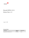
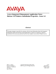
1
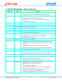
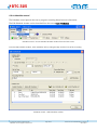
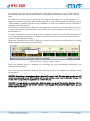
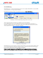
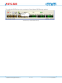
DTC-325 DtGrabber+ Advanced Transport-Stream/SDI Recorder © 2006-2015 DekTec Digital Video BV Affordable Tools for Digital-TV Professionals www.dektec.com Manual for DTC-325 DtGrabber+ Software March 2015 DTC-325 Table of Contents 1. Introduction ........................................................................................................................................ 3 2. Specifications and Minimum Requirements ............................................................................................ 4 3. DtGrabber+ Software Installation ......................................................................................................... 6 4. DTC-325 DtGrabber+ Revision History ................................................................................................. 7 5. DtGrabber+ Overview....................................................................................................................... 10 6. SNMP Remote Control ....................................................................................................................... 29 7. Support Contact information ............................................................................................................. 34 Appendix A: DtGrabber+ specific controls for DTA-160 ......................................................................... 35 Appendix B: DtGrabber+ specific controls for DTU-234 ......................................................................... 37 Appendix C: DtGrabber+ controls for DTU-235 and DTA-2135 .............................................................. 39 Appendix D: DtGrabber+ controls for DTA-2137 and DTE-3137 ............................................................. 41 Appendix E: DtGrabber+ deployment in broadcast environment : HE and STB Trouble-Shooting : Application Note..................................................................................................................................................... 42 © 2006-2015 DekTec Digital Video BV Affordable Tools for Digital-TV Professionals Page 2/44 Manual for DTC-325 DtGrabber+ Software March 2015 DTC-325 1. Introduction The DTC-325 DtGrabber+ is a cost-effective software package designed for Advanced Recording of MPEG-2 Transport Streams or SDI video signals. The DtGrabber+ is intended to be installed by the user on any qualifying PC and work in conjunction with DekTec input devices. The GUI of the DtGrabber+ displays information about the incoming signal, the recording process and the available disk space in regards with your settings and provides all the necessary controls for the fine tuning of your recording. Chapter 5 gives an overview of the GUI and details how to configure your DtGrabber+ for your specific needs. The application has integrated functionalities for scheduled captures and continuous (24H/365D) recordings. The user can set-up continuous recording as loop recording on a single file or as multiple files, depending on user needs and disk capacity. Recorded files can be set by size or duration or simply Start/Stop manually controlled. For multiple files, the auto-erase function permits to limit the maximum number of files or to delete files older than a specified number of hours. It is also possible to launch a sequential recording for a specific number of files. No packet loss occurs between consecutively recorded files. A merge tool is provided to recombine multiple sequential files and recreate the original signal. When multiple files, file names are indexed and time stamped. One can launch manually a recording on the spot or schedule it following a user-defined Schedule. The section 5.5.2 details the use of schedules. Several additional functionalities are provided. The PID filtering permits to define list and ranges of PIDs to replace selected packet by Null Packets. A log file created in the record directory keep trace of all actions by the application. The buffer is monitored and past buffer overflow are reported in the GUI, with the possibility to clear the past alarms. Real-time monitors are displayed regarding application recording run time, actual file size and the actual file duration, the disk used space and then disk remaining space. The DtGrabber+ is the ideal application for scheduled captures, broadcast signals continuous storage, or simply for your testing and troubleshooting environment. DtGrabber+ can also be used for building re-play system at your HFC network local nodes. Several instances of DtGrabber+ can run on the same host system to build cost effective multiple TS recording, for example in combination with DekTec’s DTA-124 (4x ASI Input PCI card). DtGrabber+ supports all DekTec input adapters and provides an adapted GUI for specific inputs like DTU-234 and DTA-160. © 2006-2015 DekTec Digital Video BV Affordable Tools for Digital-TV Professionals Page 3/44 Manual for DTC-325 DtGrabber+ Software March 2015 DTC-325 2. Specifications and Minimum Requirements 2.1. Key Attributes Parameter Input Rate Value 0…214 Mbit/s* * for DVB-ASI with DTA-120, DTA-124, DTA-140 , DTU-225 or DTU-245 but DVB-SPI with DTA-122: 108 Mbit/s (max. DVB/SPI rate) 2.2. Minimum PC Requirements Platform Windows XP SP3 / Vista SP2 / 2003 SP2 / 2008 SP2 / Windows 7 / Windows 8 Processor [email protected]** (minimum) 512MB (minimum) RAM ** Or equivalent AMD processor 2.3. Supported DekTec Adapters The DtGrabber+ supports the following DekTec adapters: © 2006-2015 DekTec Digital Video BV Affordable Tools for Digital-TV Professionals Page 4/44 Manual for DTC-325 DtGrabber+ Software March 2015 DTC-325 Type Description Input(s) Output(s) DTA-115 OFDM Modulator / UHF Upconverter for PCI Bus DVB-T or DVB-H with 1 In/Out ASI Port for DVB-ASI 1x DVB-T/H/QAM/ ISDBT output 1x DVB-ASI*** DTA-120 DVB-ASI Input Adapter for PCI Bus 1x DVB-ASI DTA-122 DVB-SPI (LVDS) Input Adapter for PCI Bus 1x DVB-SPI DTA-124 Quad ASI/SDI Input Adapter for PCI Bus 4x DVB-ASI DTA-140 DVB/ASI Input+Output Adapter for PCI Bus DVB-ASI 1x DVB-ASI DTA-145 Multi-Purpose ASI/SDI Adapter for PCI Bus 2x DVB-ASI*** DTA-160 GigE TS-over-IP + 3 ASI Ports for PCI Bus TS-over-IP or DVB-ASI 1x Gig-E 3x DVB-ASI**** DTA-2131 Multi-Standard VHF/UHF Receiver for PCI Express 1x RF DTA-2135 Dual DVB-T RF Input for PCI Express Bus 2x DVB-T RF DTA-2136 Dual-Channel QAM-A/B/C Receiver for PCI Express 2x QAM RF DTA-2137 Dual DVB-S/S2 RF Input for PCI Express Bus 2x DVB-S/S2 RF 1x DVB-ASI 2x DVB-ASI 2x DVB-ASI**** DTA-2138 DVB-T2 / DVB-C2 Receiver for PCI Express 1x C2/T2 RF DTA-2139 Twelve-Channel QAM-A/B/C Receiver for PCI Express 12x QAM RF DTA-2144 Multi-Purpose ASI/SDI Adapter for PCI Express Bus 4x DVB-ASI**** DTA-2145 Multi-Purpose ASI/SDI Adapter for PCI Express Bus 2x DVB-ASI*** DTA-2152 Dual-Port HD-SDI Adapter with Genlock 2x SD/HD-SDI 1x Loop Through Analogue genlock DTA-2154 Quad-Port HD-SDI/ASI Adapter with Genlock 4x SD/HD-SDI / ASI Analogue genlock DTA-2160 GigE + 3x ASI Ports for PCI Express 1x Gig-E 3x DVB-ASI**** DTA-2162 Advanced Network Card with Dual GigE Ports 2x Gig-E DTA-2174 Quad 3G-SDI/ASI with 4K Support and Genlock 4x 3G-SDI / ASI DTU-225 DVB-ASI Input Adapter for USB 1x DVB-ASI DTU-234 QAM-B Input Adapter for USB 1x RF QAM-B DTU-236A 8-VSB / QAM-A/B/C RF Probe and ASI Input for USB 1x RF QAM 1x DVB-ASI DTU-245 DVB-ASI Input+Output Adapter for USB 1x DVB-ASI DTU-351 HD-SDI Input for USB-3 1x SD/HD-SDI DTE-3120 Networked DVB-ASI Input Adapter. 1x DVB-ASI DTE-3137 Networked DVB-S/S2 RF Input. 1x DVB-S/2 RF 1x DVB-ASI 1x DVB-ASI *** 2x Output, or 1x Input + 1x Output **** bi-directional Input/Output ASI port © 2006-2015 DekTec Digital Video BV Affordable Tools for Digital-TV Professionals Page 5/44 Manual for DTC-325 DtGrabber+ Software March 2015 DTC-325 3. DtGrabber+ Software Installation 3.1. Installation The DtGrabber+ software installation is self-explanatory. The “DtGrabber+ SetUp.exe” program will guide you through the installation process. The latest version of ‘DtGrabber+ SetUp.exe’ can be found in the download section of the DekTec website, at http://www.dektec.com/downloads. The DtGrabber+ requires the Dta1xx device driver for PCI cards or Dtu2xxx device driver for USB adapters. The setup program includes an option to install the Dta1xx/Dux2xxx device driver. It is recommended to always install the included driver. The installation process will automatically check the version number of the driver, and leave the current driver on the system if it is newer than the driver in the install package. 3.2. Cautions and Recommendations ・ Virus-detecting software (e.g. Norton Internet Security, McAfee Internet security) or Windows Update tasks or any wake-up routines affects your CPU and hard-disk performance especially when continuous 24H recording set-ups and may result in DtGrabber+ buffer overflow and data loss or corruption. Therefore it is recommended to disable all those anti-virus softwares and other routines tasks from your system for professional applications. ・ Trash Can setting. For continuous recording applications, make sure that the hard-disk that is used for recording has its Trash Can’s property set not to keep deleted files. With this check, you will prevent your hard-disk to get progressively overloaded by old deleted files. For Trash Can properties, right click on the Trash Can icon from the Desktop. ・ Continuous recording shortens lifetime of HDDs. For professional continuous recording, please maintenance it at regular intervals. We do recommend the use of external HDD devices to avoid risk to your main system and system reinstallation nuisances. ・ Prevent from operating your Record hard-disk with large file browsing or large file operations while your DtGrabber+ is running to prevent affecting your recording or your disk performances. ・ For rates above 120Mbps, use an SSD drive or striped array. Recording of 3G-SDI signal requires a RAID setup of two SSD drives. © 2006-2015 DekTec Digital Video BV Affordable Tools for Digital-TV Professionals Page 6/44 Manual for DTC-325 DtGrabber+ Software March 2015 DTC-325 4. DTC-325 DtGrabber+ Revision History Revision Date Change V1.18.3.368 2015.03.12 ・ Added DTA-2174 3G-SDI support ・ T2MI output TS rate is configurable (DTA-2131/2138) V1.17.2.352 2014.11.05 ・ Added L.3 baseband frames capture (DTA-2137) ・ Added DVB-T2 Lite support (DTA-2131) ・ Added support for user-configurable IQ sampling rate ・ Fixed SNMP related issues V1.16.4.303 2014.03.12 ・ Various fixes V1.16.2.282 2014.01.21 ・ Added DAB support for DTA-2131 V1.15.1.259 2013.12.05 ・ Added DTU-2154 support V1.15.0.250 2013.11.05 ・ Added DTU-351 support V1.14.4.241 2013.09.10 ・ Fixed SDI recording modes V1.14.3.237 2013.08.14 ・ Fixed multiple files recording issue V1.14.2.233 2013.07.08 ・ Added support for DTA-2162 (dual link reception supported) ・ Added ISDB-T and T2MI support for DTA-2131 ・ Added DTU-236 support V1.12.3.195 2013.04.10 ・ Correction in the setup file V1.12.2.189 2013.03.19 ・ Added support for DVB-T, DVB-T2, DVB-C2 on DTA-2131 ・ Added support for DVB-T, DVB-T2, DVB-C, DVB-C2 on DTA2138 ・ Fixed SNMP feature for Windows Vista / Windows 7 ・ Added file name timestamp feature for Manual Recording V1.11.7.150 2013.02.19 ・ Corrected behaviour of DTE devices V1.11.6.140 2013.01.08 ・ Corrected bitrate calculation for local Ethernet interface inputs ・ Added correction for support on Windows Server 2003 V1.11.2.119 2012.11.09 ・ Added support for DTA-2139 device V1.10.0.95 2012.10.05 ・ Improved writing speed of HD-SDI video format recording ・ Added support for DTA-2131 device ・ Added IQ samples recording mode for DTA-2131 device V1.9.0.94 2012.08.16 ・ Added support for HD-SDI video format ・ Added support for DTA-2152 device ・ Fixed blinking GUI glitches ・ Fixed lost packets problem when recording multiple files ・ Added CNR and BER report, along with improved user experience, for DTA-2137 and DTE-3137 ・ Fixed IP setting problem for DTA-160 and DTA-2160 © 2006-2015 DekTec Digital Video BV Affordable Tools for Digital-TV Professionals Page 7/44 Manual for DTC-325 DtGrabber+ Software March 2015 DTC-325 v1.8.0.93 2012.08.03 ・ Fix for dropped packets when recording and merging several files v1.8.0.92 2012.05.16 ・ Support for Dta and Dtu V4 drivers v1.7.5.90 ・ DTE-3137 support ・ Added Raw Recording mode v1.7.4.84 2011.09.28 ・ Fix for crash when selecting an ASI interface V1.7.3.83 2011.09.26 ・ DTA-2136 support ・ Correction for DVB-T recording V1.7.2.81 ・ Correction for handling of –bufsize option ・ Added a command line option “-autostart” to start recording when DtGrabber+ is started ・ Increased the maximum number of schedule data from 20 to 100 V1.7.1.72 ・ DTA-2137 LNB control (Polarization and 22Khz tone) and RF reception statuses added ・ DTE-3120 support (Need to be launched with “DtGrabber+ –dte” command) V1.7.0.71 ・ Support for recording a TsoIP received with via a local NIC (NOTE: requires a DekTec device with valid license) ・ Improved disk writing performance ・ Add command line option through which the size of the record buffer can be set (-bufsize <size_in_MB>) v1.6.4.68 2010.02.01 ・ Fixed issue with roll-over from file xxxxxxx_99999.ts to xxxxxxx00000.ts v1.6.3.67 2009.11.05 ・ DTA-2137 support ・ Repeated (every X day) schedule control ・ Multiple File scheduled recording with automatic schedule resuming ・ Transition between connected schedules without packet loss ・ 5 minute prior recording folder pre-access check with SNMP Alarm trap sending v1.6.1.63 2009.07.28 ・ SNMP Get possible for recording status: Record Task Total Run Time, Actual File Recorded Time, Actual FileSize, Disk Used Space ・ Miscelleanous details correction for displays and controls ・ Correction for activation/deactivation of message Logging ・ Prevention for dangerous setting changes while recording v1.5.8.59 2008.09.17 ・ Support for 2135, 235 and DVB-T channel lists ・ Null Packet dropping possible with PID Filtering ・ File auto-erase logic completed for cases when application is stopped and/or system is rebooted. ・ Automatic storing of window geometry depending on input v1.5.6.55 2008.07.14 ・ Option setting to enable auto-deletion of file older than the recording start time v1.5.6.53 2008.01.7 ・ Support for gathered Snmp Trap sending and for large of character strings within Snmp Traps ・ Correction for TS file start and stop to be at TS packets bounds © 2006-2015 DekTec Digital Video BV Affordable Tools for Digital-TV Professionals Page 8/44 Manual for DTC-325 DtGrabber+ Software March 2015 DTC-325 v1.5.5.52 2007.11.07 ・ Correction of frequency List for QAM64-B and QAM256-B ・ RF Level display for DTU-234 ・ Snmp improvement for numerous and large of character strings v1.5.4.48 2007.09.26 ・ Support for recursive Loop recordings ・ SNMP Control for DTA-160 IP settings. ・ Corrections for SNMP Trap OIDs and for managment of multiple and continuous DtGrabber+ sessions. V1.5.2.41 2007.07.13 ・ Correction for Schedule control ・ Correction for DTU-234 ATSC mode v1.5.1.39 2007.06.20 ・ SNMP Remote Control ・ Options settings v1.4.2.35 2007.04.09 ・ Correction for handling of DTU-234 modulation types v1.4.2.34 2007.03.29 ・ Correction for SDI File header and SDI recording ・ Bug Fix to prevent OverFlow when PID Filtering ・ Change to XML format for Schedule File v1.4.0.30 2007.03.01 ・ Scheduling: spot schedule or day of the week. Save and open of schedule file, auto-erasing of old schedules ・ PID Filtering (according to our market requirement, replacement of user defined PID, or intervals of PIDs by NULL Packets) ・ Multiple file recording for a fix number of files (So far, multiple file recording was always used together with auto-erasing rules) ・ Management of settings (registry) per inputs (Necessary for simultaneous recording of multiple streams. I advise to erase previous registry folder of DtGrabber+) ・ Support of DTU-234. ・ Some bug fix for window management with DTA-160 ・ SDI Controls added v1.3.0.25 2006.11.13 ・ Support for DTA-160 TS over IP ・ New look-and-feel ・ Hard disk space checks and prevention messages ・ Message logging into log file v1.2.0.14 2006.8.28 ・ Recompilation with latest drivers. v1.1.0.9 2006.1.11 ・ Loop-file for single file recording ・ Multiple-files advanced functionalities: erasing file automatically older than X hours, setting Max number of files, creating files with Time stamp and index-number stamp ・ Merging tool to combine several files © 2006-2015 DekTec Digital Video BV Affordable Tools for Digital-TV Professionals Page 9/44 Manual for DTC-325 DtGrabber+ Software March 2015 DTC-325 5. DtGrabber+ Overview 5.1. Launching the DtGrabber+ Start the DtGrabber+ program from the Start Menu: start->All Programs->DEKTEC->DtGrabber+, or from your desktop click on the DtGrabber+ shortcut, if available. DtGrabber+ application icon: 5.2. DtGrabber+ Application General Layout 1 2 5 3 6 4 7 8 9 10 Application general view 1. Menu Bar: The top area of the DtGrabber+ application contains four menus: Recorder, Tools, Adapter and Help. 2. Adapter: This area displays the selected adapter and information about incoming signal like TS Sync, Packet Size and bit-rate of the incoming Transport Streams. Depending on the type of adapter, specific settings appear in this area 3. Record File Setting: This area displays all the information and settings for the configuration of your recording. On the top of this area is displayed the Record File name. 4. File Type: This area permits the user to define Record File by duration, by size or manually controlled. © 2006-2015 DekTec Digital Video BV Affordable Tools for Digital-TV Professionals Page 10/44 Manual for DTC-325 DtGrabber+ Software March 2015 DTC-325 5. Record Option: This area provides controls to select between Single File recording or Multiple File recording. For Single File recording, the loop recording can be selected. For multiple files, a specific number of file can be defined or unlimited number of files can be created through the setting of auto-erase rules detailed in section 4.3.3 6. Estimates View: This area displays estimates for File Duration, File Size and Total Size required for your recording configuration. 7. Control Area: This area provides buttons for controls (ex: Start, Stop) and activation of functionalities (Schedule, Snmp control, PID filtering,.. ) of the recording application. 8. Buffer Monitoring: This area displays the status of the hardware buffer and reports when overflow occur. A [Clear Alarm] button permits you to clear and acknowledge past alarm. 9. Process monitors: This area displays monitors of the recording process including the total time of your recording configuration, the actual file recording time, the actual file size, the overall disk space used by your recording and the remaining disk space 10. Message Bar: Messages displayed in the bottom bar includes event reports, errors, warnings and information from the application. Type of input and of the adapter type info are displayed on the right side. 5.3. DtGrabber+ Application Control 5.3.1. Menu Bar The menu bar contains four menus: 1. Recording. From the Recording menu, the user can set the Record File name and access the application Options (See section 5.6 for details about Options) 2. Tools. From the Tools menu, several tools and functionalities are provided like the merge tools, the schedule control or the PID filtering set-up. (See section 5.5 for details about the several tools) 3. Adapter. The Adapter menu provides common information about the current adapter and a detailed setting window depending on your adapter, like for DTA-160 or DTU-234 (See Appendix A and Appendix B about how to control those devices) 4. Help. The help menu displays contact information for sales and technical support regarding DekTec products. It displays the current version of the application. 5.3.2. Adapter Area This area indicates the selected adapter and provides information regarding the input signal. It can provide specific controls like of SDI recording settings, or adapter-related settings. Adapter Area – common view For MPEG2 TS input, two LEDs are present for signal detection and for TS Sync. Packet size and TS rate are reported. © 2006-2015 DekTec Digital Video BV Affordable Tools for Digital-TV Professionals Page 11/44 Manual for DTC-325 DtGrabber+ Software March 2015 DTC-325 For SDI input signals, only one LED (signal) is present. After selecting the SDI Input Mode, video input’s number of lines and signal rate are displayed. Specific settings as Huffman compression and recording method (Video Frame/Full Frame, 8bits/10bits) are available. NOTE: for 10-bit full frame SDI recording with a DTU-225 or DTU-245 it is recommended to use Huffman compression. SDI parameters The Adapter Area controls may vary depending on the selected adapter, as for the DTU-234 or the DTA-160 DTU-234 Adapter View DTA-160 Adapter View Note that additional adapter specific settings can be found in the menu Adapter->Settings. See Appendix A and B for details. The button displays the hardware adapter info window, like for the menu Adapter->Info. 5.3.3. Record File Settings This area gathers all the settings for your recording, from Record File name control to detailed settings. Record File Settings © 2006-2015 DekTec Digital Video BV Affordable Tools for Digital-TV Professionals Page 12/44 Manual for DTC-325 DtGrabber+ Software March 2015 DTC-325 Below the File Name setting box, three sub areas: File Type, Record Option and Estimates are provided. File Type File Type selection Specify the type of Record file control: Duration (HH:MM:SS), by size (MB) or manually controlled. Record Option Record Option settings The Record Options permit you to select between Single File Recording and Multiple File Recording. For simple recording on the spot, select “Single File Recording” for the creation of a unique file. One can set-up a continuous recording on one single file by selecting the “Loop File” option. If “Loop File” is enabled, after the Record File reaches its maximum size or duration, incoming packets will be continuously written from the begin of the file by overwriting progressively the oldest packets. When the record is stopped, the DtGrabber+ reprocesses packets from the file to rebuild the TS signal as originally received by the adapter. One can launch a sequence of multiple files recording by enabling the “Multiple Files” option and set-up the target number of files. If no auto-erase rule is selected, the recording will stop after the last file has been recorded. Auto-erase rules permits to set-up continuous recording with multiple files. Two type of automatic deletion of old files are available: “Auto-erase with max. number of Files” for automatic deletion of old files so to keep always the maximum number of files as specified by the user; and “Autoerase after xx (hours)” rules to erase automatically files older than a specified number of hours. For multiple file recording, file names are stamped with the host PC time at time of file creation and a 5 digit file index. To rebuild a TS File from sequentially created files, the user can use the “merge” tool from the Tools->Merge menu. See section 5.5.1 for description about the merge tool. © 2006-2015 DekTec Digital Video BV Affordable Tools for Digital-TV Professionals Page 13/44 Manual for DTC-325 DtGrabber+ Software March 2015 DTC-325 Estimates View Estimates View This view provides estimation of File Duration and File Size and the overall size required for your recording depending on your settings. For instance in the case of continuous recording with 50 multiple files of 10 minutes each at a rate 31.6 Mbps, one file will requires 2263 MB and the continuous recording will requires 110.5 GB approximately. DtGrabber+ will check available space in regards with those estimates to validate the start of your recording. 5.3.4. Control Area Control Area – Before Start of recording This area provides the basic controls to Start and Stop the recording or to activate the schedule control, the SNMP remote management and PID filtering. Note: Starts and Stops times are traced in the log file. For multiple file recordings, File creation and deletion times are traced in the log file (refer section 5.4 for description about DtGrabber+ logs) The Control Area includes specials monitors like the Buffer Monitoring and the Process Monitors. 5.3.4.1 Buffer Monitoring The input adapter (hardware) buffer status is displayed in real-time and a green LED indicates the normal status. Control Area – While recording © 2006-2015 DekTec Digital Video BV Affordable Tools for Digital-TV Professionals Page 14/44 Manual for DTC-325 DtGrabber+ Software March 2015 DTC-325 When incoming the data speed is higher than the disk capacity, this will result in Buffer overflow and data loss. When overflow occurs, the led turns to red then orange and the “overflow” message will be reported. (See section 5.3.5 for Message Bar and 5.4 for DtGrabber+ logs explanation) Control Area – Buffer Overflow If the overflow persists, the application will try periodically to restore itself by purging the buffer. The overflow most likely disappear by itself after occurrence but for the operator to know afterward that it occurred and that data may have been corrupted, the application will keep displaying the orange LED and the message overflow. Control Area – After Overflow The operator can clear the overflow alarm by pushing the [Clear Alarm] button on the right of the Control Area. Note: All events related to overflow are reported in the Message Bar and traced in the log file (See section 5.3.5 for Message Bar and 5.4 for DtGrabber+ logs explanation) 5.3.4.2 Process Monitors The Process Monitors report Record process periods and disk usage. Are displayed Record task Total Run Time, Actual File Record Time, Actual File Size, Disk Used Space and Disk Available space. 1. Record task Total Run Time. This monitor displays the overall running time since the record task was started. For continuous recording like Loop recording or Multiple Files recording with auto-erase rule, the time will keep increasing until the record is stopped by the user. For single file recording without Loop, the monitor will be reset to 0 every time a new record is started. 2. Actual File Record Time. This monitor displays the record time of the actual Record File. For Multiple File recording, this monitor is reset every time a new file is created. For Loop File, this monitor keeps displaying the file maximum duration after the first loop is reached. 3. Actual File Size. This monitor displays the record time of the actual Record File. For Multiple File recording, this monitor is reset every time a new file is created. For Loop File, this monitor keeps displaying the file size after the first loop is reached. 4. Disk Used Space. This monitor displays the overall space used for the current recording task. © 2006-2015 DekTec Digital Video BV Affordable Tools for Digital-TV Professionals Page 15/44 Manual for DTC-325 DtGrabber+ Software March 2015 DTC-325 Note that the memory spaces displayed refer only to the actual Record done by the instance of the application and doesn’t take into account other instance of DtGrabber+ that may be running simultaneously on the same host PC. 5. Disk Available Space. This monitor displays the remaining space on the selected disk. In case the user starts a recording exceeding the available disk space, the following pop-up message will be displayed and the recording will be cancelled. Starting a recording with insufficient disk space Note: The application will generate an information message when the available disk space will reach a value lower than 2GB, a warning message when less than 200 MB and the application will stop when less than 100MB remains on the disk. The default values for those events/messages can be customized the Options (See section 4….) 5.3.5. Message Bar The bottom Message Bar displays messages from the application on the left and type of input and adapter on the right. Message Bar – Example of message from the application Messages can be status information regarding the recording process (ex: “Ready”, “Recording”) or report of application actions (ex: “New File Created”, “File Deleted”, “File Reordering”) or information, warning or error messages like overflow messages, insufficient disk space, etc.. Most of the messages are simultaneously traced in the log file (See section 5.4 for detailed message list and explanation about logging). © 2006-2015 DekTec Digital Video BV Affordable Tools for Digital-TV Professionals Page 16/44 Manual for DTC-325 DtGrabber+ Software March 2015 DTC-325 5.4. DtGrabber+ Messages and Logs 5.4.1. Application Messages The DtGrabber+ application generates messages in the Message Bar, in a Log File and as SNMP Trap if enabled so. Three levels of message are considered: INFO (Information), WARN (Warning) and ALAR (Alarm) for Alarm messages when recording or the quality of the recording is affected. The following table provides the list of all messages: Message Level Comment Input Signal Detected INFO Input Signal Lost ALAR Ready INFO Recording started INFO Recording failed to start ALAR Common message for both SDI and TS recording Invalid input SDI signal. Recording aborted! ALAR Specific message for SDI recording File created: FileDirectory + FileName INFO New file created: FileDirectory + FileName INFO Only when Multiple File recording Deletion of old file: FileDirectory + FileName INFO Only when Multiple File recording with auto-erase rule ALAR Only when Multiple File recording with auto-erase rule Failed deletion of old file: FileDirectory + FileName ALAR Hardware Overflow ALAR Application purges automatically the buffer if too many occurrences of the overflow Alarm cleared INFO When the user click the [Clear Alarm] button Recording stopped INFO File re-ordering started INFO Only after stopping a Loop File recording File re-ordering finished INFO Only after Loop File recording Information: Less than 2GB remaining on your HardDisk INFO WARNING! Less than 200MB remaining on your Hard-Disk WARN DANGEROUS! System halted due insufficient Hard-Disk space ALAR Connected to SNMP service INFO Failed to connect to SNMP service ALAR Disconnected from SNMP service WARN Hardware Overflow. Too many recovery, Buffer is purged occurrences without If less than 100MB on disk, the application stops automatically the recording. DtGrabber+ Log message list Note that some additional and more detailed information can be displayed in the Message Bar (ex: Loop File Reordering progress: 75%, ..) © 2006-2015 DekTec Digital Video BV Affordable Tools for Digital-TV Professionals Page 17/44 Manual for DTC-325 DtGrabber+ Software March 2015 DTC-325 5.4.2. Message Logging All messages generated by the application are logged into the file “DtGrabberLog.txt” which is created automatically into the Record File directory. The following provides an example of logs generated by the application with a Multiple File recording with auto-erase rule for maximum 5 files. It provides details about times where file are created and deleted. In this example, a TS Sync loss is reported. 2007-02-27 2007-02-27 2007-02-27 2007-02-27 2007-02-27 2007-02-27 2007-02-27 2007-02-27 2007-02-27 2007-02-27 2007-02-27 2007-02-27 2007-02-27 2007-02-27 2007-02-27 2007-02-27 2007-02-27 2007-02-27 16:50:53 16:50:55 16:50:55 16:50:55 16:51:12 16:51:29 16:51:45 16:52:02 16:52:19 16:52:36 16:52:36 16:52:52 16:52:52 16:53:06 16:53:07 16:53:10 16:53:10 16:53:15 Input Signal Detected Recording started File created: C:\Record_20070227_165055_00001.ts Information: Less than 2GB remaining on your Hard-Disk New file created: C:\Record_20070227_165112_00002.ts New file created: C:\Record_20070227_165129_00003.ts New file created: C:\Record_20070227_165145_00004.ts New file created: C:\Record_20070227_165202_00005.ts New file created: C:\Record_20070227_165219_00006.ts New file created: C:\Record_20070227_165236_00007.ts Deletion of old file: C:\\Record_20070227_165055_00001.ts New file created: C:\Record_20070227_165252_00008.ts Deletion of old file: C:\\Record_20070227_165112_00002.ts Input Signal Lost Input Signal Detected New file created: C:\Record_20070227_165310_00009.ts Deletion of old file: C:\\Record_20070227_165129_00003.ts Recording stopped DtGrabber+ Log File – Example of logs generated by the application Note: by default, the log file is created as “DtGrabberLog.txt” within the Record File directory. Therefore it is recommended when running several instance of DtGrabber+ on a same host PC to use separate directory for each recording, or to specify separate log file names per input in the Options (See section 5.6 for details about Options). © 2006-2015 DekTec Digital Video BV Affordable Tools for Digital-TV Professionals Page 18/44 Manual for DTC-325 DtGrabber+ Software March 2015 DTC-325 5.5. DtGrabber+ Tools 5.5.1. Merge tool After recording with multiple file option, one may need to rebuild the original signal from sequentially created files. For this purpose, the merge tool was created. To launch the tool, access the following menu: Tools->Merge Merge tool – Access the merge tool from the Tools menu From the Merge Files window, select first your input files from the “Select” button then click on [Merge] button to perform the merging. A pop-up window will indicate you when the process is completed. Merge tool – Merging five files Note that a maximum of five files can be selected by the merge tool, but one can use the merge tool recursively to combine as much as files as necessary. © 2006-2015 DekTec Digital Video BV Affordable Tools for Digital-TV Professionals Page 19/44 Manual for DTC-325 DtGrabber+ Software March 2015 DTC-325 5.5.2. Schedule control The Schedule control permits the user to program recording based on time information. The Edit Schedule window can be launched from the menu Tools->Schedule Schedule control – Access the Edit Schedule window from the Tools menu From the Edit Schedule window, enter Schedules info by setting the Day and the Time of the recording. Schedule control – Edit Schedules window © 2006-2015 DekTec Digital Video BV Affordable Tools for Digital-TV Professionals Page 20/44 Manual for DTC-325 DtGrabber+ Software March 2015 DTC-325 In the Set Up Day area, one can specify a date (“One-Shot” recording), or one or multiple day of the week (like every Wednesday and Friday), or a repeatation every X days starting from a specific date. In the Set Up Time area, one can specify the recording start and stop times. It is also possible to specify a multiple file recording. After checking the path on disk for the scheduled recording, click on “Add Schedule” to add the schedule to your Schedule List. Each new schedule receives an ID and is displayed in the Schedule List. If the Start Time is later then the Stop Time, the application will assume automatically that Stop Time is for the following day of the start time. If so, the End Time will be displayed with mention “(+1)” in the Schedule List To save a schedule list in a text file or to restore a schedule list from file, use the “Save Schedule List” and “Open Schedule List” buttons. To delete a schedule from the list, click on the schedule ID and push the “Delete Schedule” button. When your schedules are correctly configured, make sure to activate the schedule control by clicking on the Schedule button from the main window. Enable schedule control Schedule control – Enabling schedule control When the Schedule control is enabled, the recordings will start automatically according to the Schedule list information. Due to the nature of schedule recording (Start and Stop time), it is not possible to schedule a loop file recording. CAUTION: Schedules are executed according to the host PC system’s clock. Therefore make sure that your PC clock is properly synchronized. Old schedules will be automatically erased from the Schedule list once it is started or it is recognized by the application as a time in the past. CAUTION: If a new schedule is added with a Start time before the current time and the Stop time after the current PC time, the schedule will not start unless the “Auto resume of the current schedule” option (see 5.6.5 Schedule option) is activated. © 2006-2015 DekTec Digital Video BV Affordable Tools for Digital-TV Professionals Page 21/44 Manual for DTC-325 DtGrabber+ Software March 2015 DTC-325 5.5.3. PID Filtering The PID Filtering is a simple functionality that permits user to replace defined PID or interval of PIDs with Null Packets, or to simply drop Null Packets. The PID Filtering Settings window is launched from the menu Tools->PID Filtering PID Filtering – Access the PID Filtering setting window from the menu Check “Drop Null packets after filtering” checkbox to drop all Null Packets. In the middle edit box, the user can specify the list of item by separating them with space (“ “) character (see below). Each item can be either a PID value or a PID interval defined with two PID values separated with a dash (“-“) character in between. PID Filtering – Settings window The PID Filtering can set as positive or negative. Positive filtering means that all defined PIDs or PID intervals will be replaced by Null Packet. Negative filtering means that those PID not belonging to the list of PIDs or PID intervals will be replaced by Null Packet. Caution: Using PID Filtering consume additional CPU load. For continuous recording, we advise you to monitor your CPU performances in regards with the input TS and PID Filtering settings before installation. © 2006-2015 DekTec Digital Video BV Affordable Tools for Digital-TV Professionals Page 22/44 Manual for DTC-325 DtGrabber+ Software March 2015 DTC-325 To enable the PID filtering, make sure that the Control button PID Filtering is pushed Enable PID filtering PID Filtering – Enable PID Filtering © 2006-2015 DekTec Digital Video BV Affordable Tools for Digital-TV Professionals Page 23/44 Manual for DTC-325 DtGrabber+ Software March 2015 DTC-325 5.6. Options The options are available from the menu Recorder->Options and permit to fine-tune detailed settings of the application. All the options settings are saved in the windows registry in regards with the adapter input selected. 5.6.1. Message Logging options From this window, the user can enable or disable the Message Logging, but can also specify the Log File Name. The message logging file is saved by default in the same directory as the recording file, but if the user want to specify a different directory uncheck the “Use the recording directory” option. DtGrabber+ Options settings – Message Logging 5.6.2. Disk Monitor options From this window, the user can specify threshold levels for Disk Available Space to perform following actions: - Generate an information (INFO) message when Disk Available Space reaches less than a certain value. - Generate a warning (WARN) message when Disk Available Space reaches less than a certain value. - Generate an error (ERR) message and stop the recording when Disk Available Space reaches less than a certain value. The user can also disable the Disk Monitor by unselecting the “Activate Disk Monitor” checkbox. © 2006-2015 DekTec Digital Video BV Affordable Tools for Digital-TV Professionals Page 24/44 Manual for DTC-325 DtGrabber+ Software March 2015 DTC-325 DtGrabber+ Options settings – Disk Monitor CAUTION: Do note that recording will not start if the Disk Available Space is less than the specified minimum size. Unless the “Cancel start of recording if not enough overall disk space” checkbox is not checked. 5.6.3. File options Timestamping in the filename can be achieved by using a set of specific tags: %Y for year, %M for month, %D for day, %H for hour, %m for minute and %S for second. Except the M for minutes and months, the rest of the letters are case insensitive. This feature is only compatible with Manual Recording mode –the rest of the modes handle timestamping of the filenames automatically. By default the DtGrabber+ will only achieve auto-erase of files that were created after the recording was started, but by unchecking the “Auto erase” checkbox it is possible to disable this control and permit the auto-erase to keep working on file that were created even before the last server reboot occurred, or the last application restart, or the last recording task restarted. This is useful when using the “auto-erase after X hours” © 2006-2015 DekTec Digital Video BV Affordable Tools for Digital-TV Professionals Page 25/44 Manual for DTC-325 DtGrabber+ Software March 2015 DTC-325 DtGrabber+ Options settings – File When recording multiple files, the File index keeps incrementing each time a new file is created, BUT the index is reset to ‘1’ every time a recording is restarted. For critical and optimal disk usage, it is necessary to keep the File Index increasing each time a new file is done and independently if the server was rebooted, the application restarted or the recording task restarted. To enable this, uncheck the “File Index” checkbox. You can also manually reset the File Index using the “Reset” button. 5.6.4. SNMP options Check/uncheck “Activate sending of SNMP Traps” checkbox to enable/disable the sending of SNMP Traps. For complete description of the DtGrabber+ SNMP control, refer Chapter 6. SNMP Remote Control © 2006-2015 DekTec Digital Video BV Affordable Tools for Digital-TV Professionals Page 26/44 Manual for DTC-325 DtGrabber+ Software March 2015 DTC-325 DtGrabber+ Options settings – SNMP 5.6.5. Schedule options The “Auto resume of current schedule” will permit to automatically start or resume a scheduled recording whenever the current time is between a Start time and a Stop time. This permits to auto resume recording if an application or the server/PC has been reset/reboot. DtGrabber+ Options settings – Schedule © 2006-2015 DekTec Digital Video BV Affordable Tools for Digital-TV Professionals Page 27/44 Manual for DTC-325 DtGrabber+ Software March 2015 DTC-325 5.6.6. Recording options If the user wants to record without notion of packets, check the “Raw Mode” option. DtGrabber+ Options settings – Recording In Raw mode, all incoming valid data bytes are stored and the Packet Size field in the main dialog is set “Raw” with orange background. © 2006-2015 DekTec Digital Video BV Affordable Tools for Digital-TV Professionals Page 28/44 Manual for DTC-325 DtGrabber+ Software March 2015 DTC-325 6. SNMP Remote Control 6.1. About SNMP Commonly used in the broadcast industry, the Simple Network Management Protocol (SNMP) is an open standard that enables management and monitoring of remotely controlled devices over TCP/IP network. SNMP is defined in RFC 1157, "A Simple Network Management Protocol (SNMP)" (*). The following link provides also a nice introduction to SNMP: http://www.cisco.com/warp/public/535/3.html (**). Similar to a client<->server configuration, an SNMP Manager (client) accesses a remote controlled SNMP Agent (server) and browse through its hierarchical structure called the MIB (Management Information Base) to check statuses and set parameters. Each node of the hierarchical structure receives an address-like OID (Object Identifier). For the SNMP Manager to know SNMP Agent’s nodes and properties, the MIB information available as a MIB file can be imported to the SNMP Manager. An SNMP Trap mechanism permits also the SNMP Agent to report information, error or any event to the SNMP Manager. The following graph shows a simple system architecture where DTU-124 connected DtGrabber+ applications (running over the network 192.168.20.x) other SNMP controlled equipments (on a separate network 192.168.30.x) are managed by a SNMP Manager (192.168.10.101). SNMP Agent #X Encoder 192.168.30.X 1U rack PC SNMP Agent #1 SNMP Agent #Y Multiplexer ・・・・ ・・・・・ 192.168.30.Y DTA-124 192.168.20.201 SNMP Agent #Z Matrix Switcher 1U rack PC SNMP Agent #2 192.168.30.Z DTA-124 ・・・・ ・・・・・ 192.168.20.202 TCP/IP TCP/IP Network Network SNMP Manager Station 192.168.10.101 1U rack PC SNMP Agent #N DTA-124 ・・・・ ・・・・・ 192.168.20.N SNMP Control – Example of SNMP Controlled Network Each DekTec function that is controllable by SNMP has its OID defined under 1.3.6.1.4.1.27070, which stands for ISO(1).ORG(3).DOD(6).INTERNET(1).PRIVATE(4).ENTERPRISE(1).DEKTEC(27070) Check section 6.4 for explanation about the OID and MIB structure of DekTec function controllable by SNMP. (*) SNMP is part of a larger architecture called the Internet Network Management Framework (NMF), which is defined in Internet documents called requests for comments (RFCs). The SNMPv1 NMF is defined in RFCs 1155, 1157, and 1212, and the SNMPv2 NMF is defined by RFCs 1441 through 1452. (**) by Cisco System Inc (Copyright 1996 © Cisco Systems Inc.) © 2006-2015 DekTec Digital Video BV Affordable Tools for Digital-TV Professionals Page 29/44 Manual for DTC-325 DtGrabber+ Software March 2015 DTC-325 6.2. How to set-up your SNMP control This section details how to enable and configure the SNMP Agent functionality for your DekTec application. SNMP Manager’s installation and configuration is not part of this scope. In the “C:\ Program Files\DekTec\DtGrabber+\” directory, you will find in addition to the DtGrabber+ executable, the VISNMP.dll file and the MIB file. The MIB file is to be passed to the SNMP Manager, while the VISNMP.dll file is an extension DLL to be used loaded by the Windows SNMP service to permit communication by your host PC/Server to permit SNMP communication toward your DekTec application. VISNMP.dll will also be called by the SNMP service provided by Windows. 6.2.1. Install the SNMP services Check that the services “SNMP Service” and “SNMP Trap Services” are available on your Windows system. Check the list of installed services in the “Start Menu”, “Control Panel”, “Administrative Tools”, “Services”. If the services are not started, start them and make sure they are automatically started by the system during system start-up. If the SNMP services are not installed yet, please go to “Start Menu”, "Control panel", "Add\Remove Programs". Click "Add/Remove Windows components". Check the checkbox "Management and Monitoring Tools". Then push on “Detail” button and make sure that "Simple Network Management Protocol" is checked and click “OK” to close the window. Then click “Next” to complete the installation. Eventually, you may need Windows installation CD inserted to complete the installation. 6.2.2. Configure the SNMP service properties Right click on SNMP service and click Properties to configure your SNMP service. To enable the sending of SNMP Trap from your machine, select the tab "Traps". Type "public" on "community name" combo box and click "Add to list" button. In order to specify the destination address for SNMP traps, click "Add" and add the IP address (for instance, type "127.0.0.1" if your SNMP Manager is on the same machine). In the “Log On” tab, check that the “Local System account” and the “Allow service to interact with desktop” are checked. Also check that the “Profile 1” is enabled. For Windows 2003 Server specially, make sure that the Administrator account is used, or that the Local System account is the Administrator account. © 2006-2015 DekTec Digital Video BV Affordable Tools for Digital-TV Professionals Page 30/44 Manual for DTC-325 DtGrabber+ Software March 2015 DTC-325 SNMP Service properties setting – Traps tab and LogOn tab Now from the tab Security, check the checkbox "Send authentication trap". Click "Add" under "Accepted community names". On appearing dialog box, select "READ WRITE" on "Community rights", enter "public" on "Community name", and click "OK". If you want to accept requests only from a particular client, then select "Accept SNMP packets from these hosts" and click "Add" underneath that. Type the host name or IP address and click "OK" on the appearing dialog box. After all this, click "Apply" or "OK" and close the "SNMP Service"’s “Properties dialog. Security tag - SNMP service properties © 2006-2015 DekTec Digital Video BV Affordable Tools for Digital-TV Professionals Page 31/44 Manual for DTC-325 DtGrabber+ Software March 2015 DTC-325 6.2.3. Confirm registry settings Although the registry settings are performed automatically by the DtGrabber+ installer, in case of any trouble please check this section’s details. To permit the Windows SNMP service to communicate with DekTec applications, the VISNMP.dll is provided and is referenced in the Windows Registry. From “Start” menu, select “Run Command” and type the command “regedit” to launch the Registry Editor. Make sure that in the location: [HKEY_LOCAL_MACHINE\SYSTEM\CurrentControlSet\Control\SNMP\Parameters\ExtensionAgents] (in case a 64 bit version of Windows is being used) or: [HKEY_LOCAL_MACHINE\SYSTEM\CurrentControlSet\Service\SNMP\Parameters\ExtensionAgents] (in case of 32 bit Windows), the following line is added: "SOFTWARE\VI\SNMP\CurrentVersion". HKEY_LOCAL_MACHINE Registry Settings – add the link to SOFTWARE/VI/SNMP/CurrentVersion Finally, check that in the location [HKEY_LOCAL_MACHINE\SOFTWARE\VI\SNMP\CurrentVersion], the following line has been added for the variable “Pathname”: ”C:\Program Files\DekTec\DtGrabber+\VISNMP.dll” and that the file is present in the C:\Program Files\DekTec\DtGrabber+\ directory. 6.3. Enabling/Disabling SNMP control from DtGrabber+ To enable the SNMP Control of the DtGrabber+, click on the Remote Control button in your control area. Once enabled, the Remote Control button will be displayed in yellow as illustrated below. © 2006-2015 DekTec Digital Video BV Affordable Tools for Digital-TV Professionals Page 32/44 Manual for DTC-325 DtGrabber+ Software March 2015 DTC-325 Enable SNMP Remote Control SNMP Control – Select SNMP Remote Control After a while (maximum 5 seconds), the DtGrabber+ will automatically connect to the VISNMP service and the message “Connected to SNMP Service” will be reported in the Message Bar. SNMP Control – DtGrabber+ connected with SNMP service Now, you can start control the DtGrabber+ through SNMP. SNMP Traps will automatically be sent to all authorized SNMP Managers. 6.4. About the OID and MIB Structure of SNMP controllable DekTec functions Multiple combination of DekTec adapters and applications can co-exist a single computer/server, which is identified by its IP address. Each DekTec function is identified by its OID node but to differentiate between the multiple adapters and application a specific OID structure has been designed. The OID root [1.3.6.1.4.1.27070] is common to all DekTec functions running on the host computer. Consecutive values designate, by order, the Application Id, the Application Inst, the TrapOrObject Indicator and finally the part which is application dependant. The Application Id is unique for each DekTec application controllable by SNMP. For instance, the Application Id for DtGrabber+ is the integer 0x04. The Application Id value can not be 0x00 (zero). The Application Inst indicates the instance number of the application for this Application Id. Depending on the Application Id, this value can be either an index related to the DekTec adapter attached to this application, or an cardinal order referring to the order in which the several instance of this application where started; ex: the first application to be started will receive the instance number 0x01, the second 0x02, etc.. The TrapOrObject indicator distinguishes between Trap (0x01) or Application Parameters and statuses (0x02). For understanding of the Application Dependant field, please refer to the MIB file included in the Installation Package and copied into the [C:\Program Files\DekTec\DtGrabber+] directory. The following graphs illustrate the MIB structure for DtGrabber+ functions. For understanding more about the MIB file structure and syntax, please refer to RFC 1213, "Management Information Base for Network Management of TCP/IP-based internets: MIB-II" © 2006-2015 DekTec Digital Video BV Affordable Tools for Digital-TV Professionals Page 33/44 Manual for DTC-325 DtGrabber+ Software March 2015 DTC-325 7. Support Contact information DtGrabber+ is developed in cooperation by DekTec Digital Video B.V. and Village Island Co., Ltd. For assistance regarding the use of DtGrabber+ contact us at: Village Island Co., Ltd. 3-19-1-5F, Shirokanedai, Minato-ku, Tokyo 108-0071 Japan Tel: +81 3 6409 6206 Fax: +81 3 6409 6207 email: [email protected] website: http://www.village-island.com DekTec Digital Video B.V. Godelindeweg 4 1217 HR Hilversum The Netherlands Tel: +31 35 2030100 Fax: +31 35 2030101 email: [email protected], [email protected] website: http://www.dektec.com © 2006-2015 DekTec Digital Video BV Affordable Tools for Digital-TV Professionals Page 34/44 Manual for DTC-325 DtGrabber+ Software March 2015 DTC-325 Appendix A: DtGrabber+ specific controls for DTA-160 When using the DTA-160’s IP port for TS over IP reception, the DtGrabber+ main window is automatically adapted to permit the specific controls for TS over IP. The IP Address and the Port number can be set from the main window. DtGrabber+ view when using DTA-160 IP port The common signal sync LED is replaced by an “Ethernet” LED showing the status of the Ethernet adapter (green for Ethernet link up). Additional settings for DTA-160’s IP port are available in the settings window from the menu Adapter->Settings. Access the DTA-160 setting window from the Adapter menu © 2006-2015 DekTec Digital Video BV Affordable Tools for Digital-TV Professionals Page 35/44 Manual for DTC-325 DtGrabber+ Software March 2015 DTC-325 As shown below, DTA-160 Adapter settings window permits the user to configure the Receive Protocol as UDP, RDP or automatic, to set IP address and Port but also to enable or disable the error correction with FEC streams received on Port number +2 and Port number +4; as well as setting Filter values for IP Address and IP Port. DTA-160’s IP Port detailed settings window © 2006-2015 DekTec Digital Video BV Affordable Tools for Digital-TV Professionals Page 36/44 Manual for DTC-325 DtGrabber+ Software March 2015 DTC-325 Appendix B: DtGrabber+ specific controls for DTU-234 When using the DTU-234 RF input device, the DtGrabber+ main window is automatically adapted to permit the specific controls for QAM (Annex B) demodulation, as modulation scheme and tuning setting. DtGrabber+ view for DTU-234 adapter Additional settings for DTU-234 are available in the settings window from the menu Adapter>Settings. Access the DTA-234 setting window from the Adapter menu © 2006-2015 DekTec Digital Video BV Affordable Tools for Digital-TV Professionals Page 37/44 Manual for DTC-325 DtGrabber+ Software March 2015 DTC-325 As shown below, DTU-234 Adapter settings window permits the user to configure the Modulation scheme and to tune the demodulator either by Channel number or by entering specific Frequency. A checkbox permits to switch between tuning by Channel or by frequency. The user can also specify the specific band for corresponding channel number and frequencies. Available bands are : Broadcast/OnAir, FCC/Cable, IRC, HRC; information necessary for Channel/Frequency conversions by the application. DTU-234 detailed settings window © 2006-2015 DekTec Digital Video BV Affordable Tools for Digital-TV Professionals Page 38/44 Manual for DTC-325 DtGrabber+ Software March 2015 DTC-325 Appendix C: DtGrabber+ controls for DTU-235 and DTA-2135 When using the DTU-235 and DTA-2135RF input device, the DtGrabber+ main window is automatically adapted to permit the specific controls for DVB-T demodulation. DtGrabber+ view for DTU-235 or DTA-2135 adapter Additional settings for DTU-235 and DTA-2135 are available in the settings window from the menu Adapter->Settings. Access the DTA-234 setting window from the Adapter menu © 2006-2015 DekTec Digital Video BV Affordable Tools for Digital-TV Professionals Page 39/44 Manual for DTC-325 DtGrabber+ Software March 2015 DTC-325 As shown below, DTU-235 and DTA-2135 Adapter settings window permits the user to tune the demodulator either by Channel number or by entering specific Frequency. A checkbox permits to switch between tuning by Channel or by frequency. DTU-235 and DTA-2135 detailed settings window © 2006-2015 DekTec Digital Video BV Affordable Tools for Digital-TV Professionals Page 40/44 Manual for DTC-325 DtGrabber+ Software March 2015 DTC-325 Appendix D: DtGrabber+ controls for DTA-2137 and DTE-3137 When using the DTA-2137 and DTE-3137 RF input device, the DtGrabber+ main window is automatically adapted to permit the specific controls for DVB-S and DVBS2 demodulation. DtGrabber+ view for DTA-2137adapter Open the DekTec adapter Info ( status: ) window to receive detailed information about the reception DekTec Adapter Info window © 2006-2015 DekTec Digital Video BV Affordable Tools for Digital-TV Professionals Page 41/44 Manual for DTC-325 DtGrabber+ Software March 2015 DTC-325 Appendix E: DtGrabber+ deployment in broadcast environment : HE and STB Trouble-Shooting : Application Note. This Application Note details and provides concrete example about how DtGrabber+ can be deployed for troubleshooting of STB and Head-End system in real broadcast environment. When broadcast engineer or operator faces a service disturbance with low occurrence, it is difficult to identify the problem without a concrete capture of the broadcast signal at the time of the problem. The reverse approach to this tricky situation is to set-up a continuous capture of the broadcast stream for a long enough period of time. A concrete example is given with a satellite operator who receives monthly claims of video disturbance on his service. From the starting point of view, the operator has no idea if he’s facing a STB problem or a service problem related with his Head-End system. Only with a concrete capture of the problem at the time it occurs, would he be able to investigate, to discriminate whether the problem is coming from broadcast signal or related to the receiver, and enforce the party responsible for this problem to resolve this problem. In this example, our satellite operator has 4 transports at 29,162 Mbps (TS rate) and wants to capture the latest 12 hours. The transports are available out of the multiplexer as 204 bytes TS packet‘s ASI signal. By a simple computation, he can evaluate that the minimum disk space of (29162168/8)*(60*60*12)*(204/188) ~= 159GB will be required (*) per TS. (*) Note that DtGrabber+ application provides also the correct estimation of total disk space per transport if the transport signal is fed with proper rate to the input adapter linked to DtGrabber+. Multiple file recording and auto-erase rule need to be set accordingly. To have a maximum of cost-efficiency for his set-up, our operator decides to capture the four ASI streams by using the DekTec DTA-124 and to execute four simultaneous instances of DtGrabber+, one for each input. As for the host PC, he chose a P4@3Ghz PC with a 1GB RAM to have sufficient and safe performances. Knowing that common 7200RPM hard-disks can support safely two streams at 30Mbps, he decides to split the four captures on two external 400GB hard-disks, setting two captures per hard-disk. 7200RP M / 400GB External hard-disks TS1 TS 2 TS3 TS 4 MUX1 MUX2 MUX3 DTA-124 ・・・・・ ・・・・ rmount Rack mount PC with DTA-124 © 2006-2015 DekTec Digital Video BV Affordable Tools for Digital-TV Professionals Page 42/44 MUX4 PC Manual for DTC-325 DtGrabber+ Software March 2015 DTC-325 For his convenience, he sets up file duration to 5 minutes and the multiple file recording with autoerase rule to 12 hours. As for Multiple File recording, every file will be created with their file name stamped with the file creation time (and an index number) to help him to retrieve the proper file after a claim will be reported or an occurrence of the problem identified. As DtGrabber+ manages settings (FileName, etc.) per input, our operator can safely defines separated folders and filenames for each input, the application will remember settings for each input. So his settings will result in : - for TS#1, D:\TS_1\TS_Record_YYYYMMDD_HHMMSS_5DigitsIndex - for TS#2, D:\TS_2\TS_Record_YYYYMMDD_HHMMSS_5DigitsIndex - for TS#3, E:\TS_3\TS_Record_YYYYMMDD_HHMMSS_5DigitsIndex - for TS#4, E:\TS_4\TS_Record_YYYYMMDD_HHMMSS_5DigitsIndex The following snapshot shows the host pc running four instances of DtGrabber+ running for each input of the DTA-124. (*) (*) In this SnapShot, the four instance of DtGrabber+ are recording on the same hard-disk. Now that the system is set-up and running, as soon as the problem will be reported the operator just need to retrieve the relevant file in regards with the time of the occurrence. If the problem is coincidently occurring at the transition between two files, he will use the merge tool (refer section 5.5.1 to build a continuous file out of those split files). © 2006-2015 DekTec Digital Video BV Affordable Tools for Digital-TV Professionals Page 43/44 Manual for DTC-325 DtGrabber+ Software March 2015 DTC-325 In order to reproduce the problem to the satellite STB, he will use DekTec DTA-107 with DTC-300 StreamXpress to replay the recorded file and eventually set-up a specific sub-loop at the specific time of the occurrence (Check StreamXpress documentation for details). He will also be able to replay and analyze any TS problem at the time of occurrence using DekTec’s DTC-320 StreamXpert with an input adapter. With similar recording set-up, one can build easily cost-effective TS storage system in regards with service needs or local broadcast requirements. Also, back-up replay system can be designed with a similar approach. © 2006-2015 DekTec Digital Video BV Affordable Tools for Digital-TV Professionals Page 44/44 Manual for DTC-325 DtGrabber+ Software March 2015