1
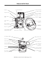
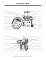
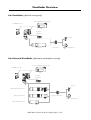
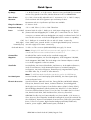
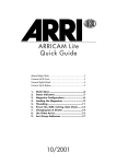
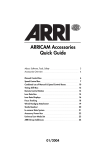
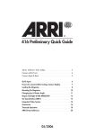
ARRICAM Lite
Quick Guide
About, Software, Tools, Safety
3
Camera Left & Front
4
Camera Right & Back
5
Camera Top and Base
6
Viewfinder Overview
7
Quick Specs
8
Messages & Warnings
9
Basic Camera Operations
10
Magazine Overview
12
Magazine Configurations
13
Loading Lite Magazines
14
Threading
16
Integrated Video System
18
ARRI Group Addresses
20
01/2004
This page is left blank intentionally.
ARRICAM Lite Quick Guide 01/2004, Page 2 of 20
About, Software, Tools, Safety
About ARRICAM Quick Guides
This Quick Guide (order number K5.58312.0) provides a short introduction to the ARRICAM Lite. Further
Quick Guides are dedicated to the ARRICAM Studio (K5.58311.0) and ARRICAM Accessories (K5.58313.0).
An overview of all ARRICAM components, a cable overview and a Ground Glass overview, is given in the
ARRICAM System Guide (K5.58314.0). These guides do not replace the ARRICAM System User’s Guide
(K5.58508.0). It is essential that you acquaint yourself with the User’s Guide before operating the equipment.
These documents can be downloaded from www.arri.com in Acrobat pdf format. The Acrobat Reader can be
downloaded free from the Adobe web site at www.adobe.com. A PostScript printer gives best printing results.
Even though all efforts have been made to ensure this guide’s accuracy, changes and upgrades to the products
described can result in different hardware or behavior. Technical data are subject to change without notice.
Software version
This Quick Guide describes the ARRICAM system with Software Packet 03E. Different software versions can
result in different behaviours. Authorized ARRI Service Centers can check and update the ARRICAM software.
Tools
Anyone operating the ARRICAM system should have these tools:
1. One end of the ARRICAM Ground Glass Tool is used to remove the ground glass and the field lens. Use the
1.5 mm metric hex wrench at the other end to adjust the Integrated Video System and Frameglow alignment.
2. A 3 mm metric hex wrench is used to attach and remove most accessories.
3. A 5 mm metric hex wrench is used to attach or remove the Camera Handle grips, the 3/8” Accessory
Shoe Adapter and the WHA-2 Rosette Bracket.
4. A 8-10mm (5/16”) flathead long shaft screwdriver is used to attach baseplates, the Magazine Stabilization
Bracket and the ARRICAM Shoulder Set. Please note that screwdrivers with a short, stubby shaft will not
work with the Shoulder Set.
Safety specifications
• The Studio Viewfinder arm (hinge type) can be angled away from the camera to swivel it to the other side
of the camera. When this is done, make sure to securely hold the viewfinder arm, as it could otherwise
swing out rapidly and might cause pain and damage.
• Never place your hand in the lens port or inside of the camera while it is running.
• Assembly and initial operation should be carried out only by persons who are familiar with the equipment.
• Switch camera power off before making electrical connections (i.e. connecting accessory boxes).
• Never run the camera without a lens or a protective cap mounted in the lens port.
• Never operate the movement locking mechanism while the camera is running.
• Always ensure that the camera is securely mounted.
• Repairs should be carried out only by authorized ARRI Service Centers.
• Use only original ARRI replacement parts and accessories!
• In wet weather conditions the normal safety precautions for handling electrical equipment should be taken.
• Clean optical surfaces only with a lens brush or a clean lens cloth. In case of solid dirt moisten a lens cloth
with pure alcohol or a brand name lens cleaner.
• Do not use solvents to clean the film path, plexiglas parts or rubber seals.
• Do not remove any screws which are secured with paint.
ARRICAM Lite Quick Guide 01/2004, Page 3 of 20
Camera Left & Front
Eyepiece
Lite Mask Frameglow
Lite Camera Handle
Video lens IRIS
Eyepiece focus
Frameglow DIMMER
Integrated Video System
Image rotation
knob
Magazine release
button
Image rotation
lock
Lite Shoulder
Magazine
Upper Extended
Camera Control Panel
Magazine
door lock
Tape hook
Lower Extended
Camera Control Panel
Magazine door
lock safety
Camera door lock safety
Camera door lock
Lite Camera Handle
Image rotation knob
Tape hooks
Viewfinder
DUST CHECK button
Image rotation lock
Power for Heated
Eyecup & Work Light
PL lens port
1 = normal 35
2 = super 35
Field lens
Power for Heated
Eyecup & Work Light
Ground Glass
Lens Data System
contacts
RS connector
(remote RUN & 24 V dc)
ARRICAM Lite Quick Guide 01/2004, Page 4 of 20
Camera Right & Back
Power on/off
switch
Lite Camera Handle
SET RAW STOCK button
Integrated Video System
SHOW/SET ASA button
Tape hook
PRESET selector switches
Viewfinder
RAW STOCK display
Lens Data Box
port cover
Lite Shoulder
Magazine
RS connectors
(remote RUN
& 24 V dc)
Camera Accessory
Connector (CAC)
Power connector (BAT)
Tape hook
Attachment rosette
Lite Camera Handle
Frameglow DIMMER
Tape hooks
Image rotation knob
Integrated Video System
Power on/off switch
Image rotation lock
Lite Mask Frameglow
Camera Accessory
Connector (CAC)
Tape hook
Power connector
(BAT)
Magazine port
ARRICAM Lite Quick Guide 01/2004, Page 5 of 20
Camera Top & Base
Lite Camera Handle
Integrated
Video System
Viewfinder
Video lens IRIS
Contrast filter
Accessory shoes
Frameglow DIMMER
Image rotation knob
Tape Measure Hook
Eyepiece focus
Lite Mask Frameglow
Eyepiece
Viewfinder
Image rotation lock
Hole for Shoulder Pad
locating pin
3/8” x 16 mounting holes
Cover for Power
Bridgeplate contacts
ARRICAM Lite Quick Guide 01/2004, Page 6 of 20
Shoulder Pad
mounting hole
Viewfinder Overview
Lite Viewfinder (spherical viewing only)
Lite Integrated Video System (IVS)
Lite 100% Video Top
Lite Mask
Frameglow
Eyecup
Lite Extension
Lite Eyepiece
Heated Eyecup
Lite Universal Viewfinder (spherical or anamorphic viewing)
Lite Integrated Video System (IVS)
Lite 100% Video Top
Lite Mask
Frameglow
UNLOCK
OPEN
LOCK
FIX
Eyecup
Studio Anamorphic Extension
Studio Zoom Extension
Lite Universal Eyepiece
Heated Eyecup
Studio Medium Extension
ARRICAM Lite Quick Guide 01/2004, Page 7 of 20
Quick Specs
Fps Range
1 to 40 fps forward, 1 to 32 fps reverse. Reverse running and 0.001 fps increments
can be set by Speed Control Box, Wireless Remote Control or ARRIMOTION.
Mirror Shutter
0° to 180°, electronically adjustable in 0.1° increments (11.2° to 180° for ramps).
Movement
5-link movement with dual registration pins and transport claws.
Movements with 4 or 3 perforation pull down are available.
Flange Focal Distance
51.98 mm – 0.01
Temperature Range
–10° to +40° Celsius /+14° to +104° Fahrenheit
Power
Nominal 24 V dc in (Pin 1: GND, pin 2: 24 V) Input voltage range: 21- 35 V dc.
24 V BAT
RS
CAC
Work Light/
Heated Eyecup
On-board Monitor
(Camera & Power Bridgeplate) Pin 1: GND, pin 2: nominal 24 V dc out. The RS
connectors on camera and Power Bridgeplate can supply a combined total of 2.5 A
max. The RS connectors on the Power Bridgeplate have no remote run capability.
Pin 1: GND, pin 2: nominal 24 V dc out with 2.5 A max. continuously.
Outer: GND, inner: nominal 24 V dc out. Work Light/Heated Eyecup connectors
can each supply 0.75 A max. continuously.
12 V dc out. This connector (MINI MONITOR) can supply 1.2 A max.
Note: Although the RS and CAC connectors can each supply 2.5A in isolation, the
shared load of all connectors combined cannot exceed 2.5 A.
Contrast Filter
An ND 0.6 filter can be moved into the viewfinder image path.
Magazines
Lite Steadicam Magazine, Lite Shoulder Magazine, Studio Magazine 120/400,
Studio Magazine 300/1000. The Studio Mag to Lite Camera Adapter is needed
to use Studio magazines on the Lite camera.
Viewfinders
Lite Viewfinder, Lite Universal Viewfinder, Lite Extension, Studio Medium Extension,
Studio Zoom Extension, Studio Anamorphic Extension, Lite Mask Frameglow,
Lite Eyepiece, Lite Universal Eyepiece, Heated Eyecup, Integrated Video System,
Lite 100% Video Top, 2” and 6.6” Video Monitors.
Note: The ARRICAM Studio Viewfinders can also be used on the ARRICAM Lite
Lens Data System
Lite Lens Data Box, Lens Data Displays (LDD & LDD-FP), Lens Data System (LDS)
zooms and prime lenses.
Electronic Accessories
Speed Control Box, Manual Control Box, Timing Shift Box, MCB Cable Adapter,
Pick-up Unit, Remote Control Station, In-camera Slate Box, Power Bridgeplate,
Work Light, Lens Control System, Controlled Lens Motors (CLM-1, CLM-2, CFM-1),
Wired Handgrip Attachment, Wireless Main Unit, Wireless Focus Unit, Wireless
Zoom Unit, Wireless Remote Control, Focus/Iris Unit, Zoom Main Unit, Iris Control
Unit, Remote Switch RS-4, CAC Distribution Box, Accessory Power Box.
Other
ARRICAM Shoulder Set, Lite Camera Handle, Lite Centre Handle, 3/8“ Accessory
Shoe, Accessory Shoe Expander, Viewfinder Levelling Rod, Universal Low Mode Set,
Ground Glasses, Aperture Format Masks, PL mount lenses, Shift & Tilt system, Matte
Boxes, Follow Focus systems, Right Camera Handgrip with RUN/STOP button,
batteries, power supplies, ARRI Dovetail system, Arrihead 2.
ARRICAM Lite Quick Guide 01/2004, Page 8 of 20
Messages & Warnings
The FPS, SHUTTER
and EXPOSED FILM displays will show messages and warnings. See the ARRICAM System User’s Guide for a complete list. The Lens Data Displays (LDD, LDD-FP) and the System Line of the
Integrated Video Systems will show similar information. Messages and warnings are as of Software Packet 03E.
FPS display
Bat
During run: Input voltage is too low. Camera continues to run. Change battery once the camera is
stopped! During standby: Input voltage is too low. The camera is not ready. Change the battery!
Bukl
A film guide or buckle trip (upper, lower or rear) has been tripped. The camera is not ready.
Cal
Lens calibration in progress. The camera is in Standby.
DC
The DUST CHECK or PHASE button has been pushed while the camera was in Standby to move the
shutter 1/2 rotation, so the film is now visible through the lens port for a dust check.
End
Less than 6m/20 ft of unexposed film remain in the magazine.
FPS!
A speed below or above the permissible fps range has been preset.
Heat
The camera and magazine heaters are on. During camera run, heaters are automatically powered down.
Jam
A discrepancy between the amount of film leaving and returning to the magazine has been detected,
indicating a film jam. Take the magazine off or turn the camera power switch off then on to reset.
Lock
While the camera is in Standby, press the UNLOCK button to allow the FPS setting to be changed.
m/ft
A magazine with a different unit of measurement to its predecessor has been attached to the camera.
The warning will disappear when the camera is running but will reappear when the camera stops.
Press the PHASE button to reset the warning. See Loading Lite Magazines section of this Quick Guide
for details of how to change the unit of measurement.
MCB
The Manual Control Box controls fps. -MCB is shown when a reverse frame rate is set.
Movm The movement block is not fully locked in its forward (shooting) position. The camera is not ready.
SCB
The Speed Control Box controls fps. -SCB is shown when a reverse frame rate is set.
SW
Minor software incompatibility. At least one component has old software. Camera run still possible
with minor operational restrictions. Press PHASE button to reset the warning; update the software.
!SW!
Major software incompatibility. At least one component has old software. The camera is not ready.
Remove accessories and restart the camera to see where the incompatibility resides.
Time
The camera has stopped after 350m/1150ft of continuous running to prevent it running indefinitely.
TkUp
The magazine feed side has tension, but the take-up side runs free. To reset, take the magazine off or
turn the camera power switch OFF and ON again.
Wind
The magazine is winding up loose film. The camera is not ready until that is finished. This message will
also appear for about 25 seconds when an empty magazine has been mounted.
SHUTTER display
ChkS
During RUN only: The secondary shutter signal is not present. The primary shutter signal shows the
shutter angle as correct. During RUN and STANDBY: The secondary shutter signal and preset shutter
angle differ. The camera will continue to run until cut, then cannot be restarted. This can be reset
temporarily by pushing the PHASE button. In either condition, check the shutter angle manually and
proceed with caution as exposure may be incorrect. Consult an ARRI Service Center.
Err
The primary shutter signal and preset shutter angle differ. If running, the camera stops and will not
restart. Consult an ARRI Service Center.
ISB0
The camera is running up or down, and the shutter has been set to 0° for In-camera Slate exposure.
Lock
Press UNLOCK button to change the shutter setting – only possible while camera is in Standby.
RUN
The camera is running, and no adjustment of the shutter can be done by the Camera Control Panel.
SCB
Speed Control Box controls the shutter, so the Camera Control Panel is unable to adjust the shutter.
WRC
Wireless Remote Control controls the shutter, so the Camera Control Panel is unable to adjust the shutter.
ARRICAM Lite Quick Guide 01/2004, Page 9 of 20
Basic Camera Operations
Power on/off switch
This is located at the back of the camera, above the Camera Accessory Connector (CAC). Characters should
be visible in the displays when the camera is on.
Inching
To manually inch the camera, open the camera door and turn the inching knob clockwise. This will rotate the
movement only, not the mirror shutter. To electronically inch the camera, hold the PHASE button down while the
camera is in Standby – this will rotate both movement and shutter at about 1 fps.
Checking the gate
To check the gate, briefly press the DUST CHECK button while the camera is in Standby. The mirror rotates out
of the way, the shutter opens fully, and the FPS display shows DC. The movement will not move. To move the
shutter back into the viewing position, briefly press the DUST CHECK button again.
Note: The DUST CHECK button does not transport the film, but does rotate the shutter. If the shutter angle was
reduced, it opens to 180° for the duration of the DUST CHECK, then returns to the previously set angle. The PHASE
button however, transports the film and rotates the shutter, leaving the angle unchanged.
Film Gate and Spacer Plate
• The surfaces of the Film Gate must be meticulously clean. When inserting the Film Gate in the camera, be sure
that the locking lever completely returns to its correct resting position, which is flush with the surface of the gate.
• An Aperture Format Mask and a Filter Holder must always be inserted in the Film Gate.
• When removing or installing the Spacer Plate, the movement should be in its rear position. Handle with care.
Camera heating
The camera and magazines are equipped with automatic heaters that switch on in very cold conditions. The
heaters can be temporarily de-activated to save power by holding the PHASE button down while switching the
camera’s power switch on. To activate the automatic heater control again, switch the camera off then on.
Camera Control Panel
On both Studio and Lite cameras, most of the functions can be controlled and monitored by means of the
Camera Control Panels. Each camera is fitted with either a Standard or an Extended Camera Control Panel.
The Standard Control Panels are equipped with FPS selector switches. On the Extended Camera Control
Panels, fps and shutter opening is set by means of buttons. These require the UNLOCK button to be pressed
to set the fps or shutter angle.
The remaining raw stock film length will be displayed when the RAW STOCK button is pressed.
What controls fps?
All frame rates are crystal controlled. Six preset fractional rates like 23.976 fps can be set with the Extended
Camera Control Panel. Reverse running and 0.001 fps increments can be set with the Speed Control Box, the
Wireless Remote Control and the ARRIMOTION.
When the camera is in standby, the FPS displays show which component controls the frame rate. A minus sign
in front of the characters means that the camera is set to reverse run. The following messages might be shown:
FPS
Controlling item
FPS
Controlling item
0.0
Standard Camera Control Panel
-SCB
Speed Control Box (reverse run)
24.0
Extended Camera Control Panel
WRC
Wireless Remote Control
ARRICAM Lite Quick Guide 01/2004, Page 10 of 20
Basic Camera Operations
Lite Standard Camera Control Panel
Lite Extended Camera Control Panel
Film length (FOOTAGE) display
Film length (EXPOSED FILM) display
RAW STOCK
button
RESET button
Battery (BAT)
LED
RESET button
UNLOCK
button
PHASE button
SET shutter
angle selector
RUN LED
PHASE
button
RUN/STOP
button
SET shutter
angle selector
SHUTTER angle
display
BRIGHT button
FPS selector
RUN/STOP
button
FPS display
RUN LED
FPS selector
FPS display
FPS selector
SHUTTER
angle display
Changing fps
Fps is set on the Standard Camera Control Panel by pushing the FPS selector buttons with a small pointed tool
while the camera is in standby. Fps is set on the Extended Camera Control Panel by first pressing and holding
the UNLOCK button then using the FPS selector buttons while the camera is in standby.
Note: Before entering the desired fps on the Camera Control Panel, ensure that no other component has control
of the camera, e.g. if the Speed Control Box is attached, its SPEED CONTROL switch has to be set to OFF. Similarly, if the Manual Control Box is connected to the camera, its MANUAL CONTROL switch has to be set to OFF
or to SHUTTER .
Changing shutter angle
To change the shutter angle with the Standard Camera Control Panel, press the SET shutter angle selector with
a small pointed tool. On the Extended Camera Control Panel, it is necessary to press and hold the UNLOCK
button while pressing the SET shutter angle button.
With either panel, each pressing of the SET shutter angle button will cycle through following values:
180°, 172.8°, 150°, 144°, 135°, 120°, 105°, 90°, 86.4°, 75°, 60°, 45°, 43.2°, 30°, 22.5°, 11.2°.
Note: Before entering the desired shutter angle on the Camera Control Panel, ensure that no other component has
control of the camera, e.g. if the Manual Control Box is attached to the camera, its MANUAL CONTROL switch
has to be set to OFF or to FPS. If the SCB is connected to the camera, make sure its COMPENSATION switch is
set to OFF or to IRIS.
ARRICAM Lite Quick Guide 01/2004, Page 11 of 20
Magazine Overview
Lite Shoulder Magazine
Lite Steadicam Magazine
ARRICAM Lite
Studio Magazine 120/400
Studio Mag to
Lite Camera Adapter
Studio Magazine 300/1000
ARRICAM Lite Quick Guide 01/2004, Page 12 of 20
Magazine Configurations
Four Magazines can be used with the ARRICAM Lite: The Lite Shoulder Magazine and Lite Steadicam
Magazine directly onto the camera and, with the use of the Studio Mag to Lite Camera Adapter, the Studio
Magazine 120/400 and Studio Magazine 300/1000. Top mounting of magazines is not possible on the Lite
camera. Only Studio Magazines allow reverse running.
Mounting Lite Magazines
Press the magazine release button on the top of the camera and remove the magazine port cover by sliding
it out sideways. Engage the dovetail of the magazine in the camera magazine port and slide it into position,
while carefully placing the film loop in the film path, as detailed in the Threading section of this Quick Guide.
Magazine
release button
Buckle trip
plate
Lite Shoulder
Magazine
Magazine
port cover
Mounting the Studio Mag to Lite Camera Adapter
Slide the Studio Mag to Lite Camera Adapter from the side onto the camera. There will be a click as it locks in
place. The Adapter is secured by three screws which have to be tightened with a 3mm metric hex wrench.
Note: When attaching the Studio Mag to Lite Camera Adapter, make sure you tighten screws 1 and 2 first, not
forgetting screw 3 (see picture below).
Magazine release button
Screw 1
Screw 2
Studio magazine
release lever
Studio magazine
release safety button
Studio Mag to Lite
Camera Adapter
Screw 3
ARRICAM Lite Quick Guide 01/2004, Page 13 of 20
Loading Lite Magazines
The following instructions pertain to Lite Shoulder Magazine and Lite Steadicam Magazine. These are both
active displacement magazines, i.e. the filmcore spindles move throughout the roll. This allows smaller overall
magazine proportions. Load unexposed film only in absolute darkness (dark room or changing tent).
Step 1: The feed side
Ensure that an empty film core is on the take-up
coreholder before starting the loading procedure.
• Push the magazine door lock safety towards the magazine
throat, lift the door lock latch and turn it counter-clockwise.
Open the door.
• Push the take-up coreholder all the way to the magazine edge
(see drawing to the right).
• Remove the film from the film can.
• Remove the tape from the film head. Ensure that the tape is
completely removed and secured out of the way.
• Lay the film roll on the empty can placed left to the magazine.
take-up
side
feed side
Magazine door
Film
Film core
Feed side film
core release
Feed side coreholder
Take-up side film
core release
Magazine throat
Magazine roller
Take-up side coreholder
Film head
• Push the film head into the left slit on the magazine throat from the inside until it emerges on the outside.
Note: When attaching a film core to a coreholder, you should hear three clicks (as described below).
• Press the feed side release knob (first click).
• Place the film on the feed side coreholder and push the film core down as far as it will go. Triggered by the
core pushing on the coreholder key, the coreholder clamps onto the core (second click).
If you don’t hear the second click, it is possible that the coreholder key slipped into the core’s key slot, and
thus did not get clamped down securely. Lift the film up from the coreholder, turn it and push down again.
• Hold the coreholder stationary with one hand (you can grab it at its edges), and use the other hand to turn
the film roll until the coreholder key engages into the film core’s key slot (third click). Failure to do so can
lead to film jams
Note: When placing film on the feed side coreholder, do not push on the film itself, as it could become conical.
ARRICAM Lite Quick Guide 01/2004, Page 14 of 20
Loading Lite Magazines
Inserting the film head into the film core
Correct
Film loop
Incorrect
Film core
Step 2: The take-up side
• Push the film head gently into the right slit on the magazine throat until it emerges inside the magazine.
• Place the film head into the film core slot (see drawing).
Note: The film head should not stick out above the film core, as this could lead to jams!
• Rotate the take-up core clockwise 4 to 5 times until 2 to 3 feet of film is firmly wound up.
• Close the magazine door. Make sure that the film is not caught in the door. Turn the magazine door lock
latch clockwise and flip it back into its recess.
• Pull up on the magazine door to double check that it is properly locked.
Step 3: Set RAW STOCK and ASA
• Enter the amount of raw stock loaded with the PRESET selector switches.
• Press the SET RAW STOCK button until you see the number from the PRESET selector switches appear in the
RAW STOCK display.
• When using the In-camera Slate system, enter the ASA of the film loaded with the PRESET selector switches.
• Press the SHOW/SET ASA button until you see the number from the PRESET selector switches appearing in
the RAW STOCK display.
Note: The RAW STOCK display normally shows the amount of raw stock left in the magazine. To view the
currently set ASA, press briefly the SHOW/SET ASA button.
• In order to change the unit of measurement, depress the SET RAW STOCK and the SHOW/SET ASA buttons
simultaneously for about 3 seconds. This can be done either while the magazine is not mounted or when the
magazine is mounted and the camera is not powered. The displayed unit (m or ft) will affect all film length
displays. If the unit of measurement on a new magazine is different to the previous magazine, then the
camera will display a warning that can be reset by pressing the PHASE button.
Note: Always make sure that a loop protector is on the magazine when it is not on the camera
ARRICAM Lite Quick Guide 01/2004, Page 15 of 20
Threading
Attaching a Lite Magazine to the camera
• Push the camera door lock safety towards the lens, lift the door lock latch and turn it counter-clockwise.
• Open the camera door.
• Depress the silver magazine release button to remove the magazine port cover.
• Turn the movement locking lever clockwise to swing the movement away from the film gate.
• Press the upper and lower film guide release knobs.
• Pull some film out of the magazine until the loop is about one hand’s width long.
• From the side, push the magazine halfway into the magazine port.
• Thread the film in the movement so that it lies between the film guides and the sprocket wheels, and between
the movement and the film gate.
• Now slide the magazine into the camera as far as it will go.
Upper buckle trip
Magazine release button
Upper film guide release
Upper sprocket
roller
Upper loop marking
Upper film guide
Movement locking lever
Rear buckle trip
Inching knob
Lower sprocket
roller
Lower film guide
Lower film guide release
Lower loop marking
Lower buckle trip
Threading the film
• Position the film on the lower sprocket roller so the sprockets engage the film perforations. Close the lower
film guide by pushing it towards the sprocket wheel. Repeat for the upper sprocket wheel.
Note: If you cannot easily close a film guide, the sprocket teeth are probably not engaged in the film perforations
exactly. Open the film guide and reposition the film. Never force a film guide!
• Turn the inching knob so the index point is at 12:00 o’clock.
• Place a finger of one hand on the film, just below the gate. With the other hand turn the movement locking
lever counter-clockwise to gently slide the movement towards the gate.
• When you feel the transport claws touch the film, slide the film a little up and down so that the transport
claws engage the film perforations. Lock the movement by turning the locking lever fully counter-clockwise.
• Now turn the inching knob so the index point is at 9:00 o’clock in the position labelled LOOP. Set the upper
and lower film loops to their marks by pressing the knob on the end of each sprocket rollers and turning.
• To check for proper film transport, turn the inching knob. Then press the PHASE button; the film will start to
run with about 1 fps.
Note: The FPS display will show the power supply voltage when the PHASE button is depressed.
ARRICAM Lite Quick Guide 01/2004, Page 16 of 20
Threading
• Run the camera briefly at 24 or 25 fps to check for proper threading. You will be able to hear if there is any
problem by the sound of film running through the camera.
• Using the same film stock that you will be using for the shoot, turn the PITCH adjustment with a 3mm metric
hex wrench while the camera is running at 24 or 25 fps until you hear the least amount of noise.
Movement locking lever
Inching knob
FWD/REV adjustment
PITCH adjust for quietest running.
• When the camera is set to run reverse and b/w film is used, the best image quality can be achieved by
setting the FWD/REV adjustment to REV. In all other cases set it to FWD.
• Close the camera door.
Note: Always make sure that a cover is in the magazine port when no magazine is attached.
Lite Steadicam Magazine
Lite Shoulder Magazine
Studio Magazine 120/400
mounted on the Studio Mag
to Lite Camera Adapter
ARRICAM Lite Quick Guide 01/2004, Page 17 of 20
Integrated Video System
MENU/STORE/MGC dial
White balance (WHITE BAL.)
button
Tape hook
White balance
mode LEDs
Video signal
(BNC MODE)
button
Accessory
shoe
On-board
Monitor (MINI
MONITOR)
connector
Video out
(BNC)
connectors
ON/OFF LED
EXT SYNC
in (BNC)
connector
S-Video (Y/C)
out connector
Video signal LEDs
Manual Gain
Control button
ON/OFF/CHECK/HIDE MENU switch
Manual Gain Control LED
ON/OFF/CHECK/HIDE MENU switch
Make sure that the camera power ON/OFF switch is ON. Move the ON/OFF/CHECK/HIDE MENU switch
on the Integrated Video System to the ON position. The ON LED will light up.
To display a summary of all menu choices while the on-screen menu is not visible, push the
ON/OFF/CHECK/HIDE MENU switch all the way down.
To temporarily hide the on-screen menu while it is visible, push the ON/OFF/CHECK/HIDE MENU switch all
the way down. This is useful to check the image while making adjustments in the on-screen menu.
White balance
Press the WHITE BAL. button to cycle through the four white balance settings:
OUTDOOR 5600° K when the illumination is daylight or HMI and no colour conversion filter is used.
INDOOR 3200° K
when the illumination is tungsten and no colour conversion filter is used.
AUTO
automatic white balance.
MAN
manual white balance as defined in the WB/GAIN sub-menu.
Controlling image brightness
It is recommended to set the video lens iris fully open to allow the Automatic Gain Control (AGC) working best
over many f-stops. Adjust the iris by turning the IRIS dial on the left side of the Lite Integrated Video System.
Since the Automatic Gain Control averages the image brightness, in some lighting situations e.g. strong back
light or if the video image is still too dark, the Manual Gain Control will yield a better video image.
ARRICAM Lite Quick Guide 01/2004, Page 18 of 20
Integrated Video System
Manual Gain Control
• Press the MGC button to toggle between Manual Gain Control (LED on) and Automatic Gain Control
(LED off).
• When MGC is on, turn (but do not depress!) the MENU/STORE/MGC dial clockwise to increase or counterclockwise to decrease gain.
The on-screen menu
The on-screen menu allows adjustment of the following features: Manual White Balance, Manual Gain Control,
video settings (e.g. video sync), Format Marking, Image Compare/Store, Text Inserter (camera status, system
status, LDS info, timecode and more), VITC/WHITELINE.
• To display the main menu, depress the MENU/STORE/MGC dial for 3 seconds.
• To select a sub-menu, turn the dial. The left arrow indicates which sub-menu is selected.
• To enter the selected sub-menu, press the dial.
• To go back to the main menu choose EXIT, which can be found at the bottom of each screen.
• To leave all menus depress the dial for 3 seconds.
BNC mode
• Press the BNC MODE button to assign which video signal will be output by the video out (BNC) connectors:
COMP.
Top BNC:
composite video without on-screen data.
Bottom BNC: composite video with on-screen data.
Y/C
Top BNC:
C (chrominance) portion of the video signal, with on-screen data
Bottom BNC: Y (luminance) portion of the video, with on-screen data.
Y/C
Top BNC:
C (chrominance) portion of the video signal, without on-screen data
Bottom BNC: Y (luminance) portion of the video, without on-screen data.
How to get black/white video
• Press the BNC MODE button to Y/C
(on-screen data visible) or to Y/C
(on-screen data not visible).
• Connect the video cable to the bottom video out (BNC) connectors.
How to preview motion blur
When a fast moving object is filmed with a slow frame rate and a wide open shutter angle, the object will
appear blurred on film (motion blur). This effect can be previewed with the Integrated Video Systems.
• Remove the magazine from the camera to save film.
• Depress the MENU/STORE/MGC dial 3 seconds to view the on-screen main menu.
• In the VIDEO CONFIG. sub-menu, set FLICKERFREE to ON.
• In the VIDEO CONFIG. sub-menu, set EXPOSURE TIME to FILM.
• Depress the dial 3 seconds to exit the on-screen menu.
• Run the camera. Now you see a close approximation of the motion blur that will be exposed on film.
Varying degrees of motion blur can be achieved by changing fps, shutter angle, lighting contrast and the
speed of object and camera movement. Motion blur is most visible at slow fps and wide open shutter angles
(e.g. 6 fps and 180° ).
ARRICAM Lite Quick Guide 01/2004, Page 19 of 20
ARRI Group Addresses
Canada
ARRI Canada Limited (Sales & Service)
415 Horner Ave. Unit 11, Toronto, Ontario M8W 4W3, Canada
Voice phone: +416 255 3335, FAX: +416 255 3399
Email: [email protected]
Germany
Arnold & Richter Cine Technik (Headquarters, Sales & Service)
Türkenstraße 89, D-80799 Munich, Germany
Voice phone: +49 (0)89 3809-0, FAX: +49 (0)89 3809-1244
Email: [email protected]
ARRI Camera Rental (Film Equipment Rental)
Türkenstraße 89, D-80799 Munich, Germany
Voice phone: +49 (0)89 3809-1240, FAX: +49 (0)89 3809-1798
Email: [email protected]
Great Britain
ARRI GB Limited (Sales & Service)
2 Highbridge, Oxford Road, Uxbridge, Middlesex, UB8 1LX, England
Voice phone: +44 (0)1895 457 000, FAX: +44 (0)1895 457 001
Email: [email protected]
ARRI MEDIA (Camera Rental)
3 Highbridge, Oxford Road, Uxbridge, Middlesex, UB8 1LX, England
Voice phone: +44 (0)1895 457 100, FAX: +44 (0)1895 457 101
Email: [email protected]
ARRI Lighting Rental (Lighting Rental)
4 Highbridge, Oxford Road, Uxbridge, Middlesex, UB8 1LX, England
Voice phone: +44 (0)1895 457 200, FAX: +44 (0)1895 457 201
Email: [email protected]
Italy
ARRI Italia S.r.l. (Sales & Service, Milan)
Viale Edison 318, 20099 Sesto San Giovanni (Milan), Italy
Voice phone: +39 (0)2 262 271 75, FAX: +39 (0)2 242 1692
Email: [email protected]
ARRI Italia S.r.l. (Sales & Service, Rome)
Via Placanica 95, 00040 Morena (Rome), Italy
Voice phone: +39 (0)6 726 707 97, FAX: +39 (0)6 723 1541
E-mail: [email protected]
USA
ARRI Inc. (Sales & Service, East Coast)
617 Route 303, Blauvelt, NY 10913-1123, USA
Voice phone: +1 914 353 1400, FAX: +1 914 425 1250
Email: [email protected]
ARRI Inc. (Sales & Service, West Coast)
600 North Victory Blvd., Burbank, CA 91502-1639, USA
Voice phone: +1 818 841 7070, FAX: +1 818 848 4028
Email: [email protected]
CSC Camera Service Center (Film Equipment Rental, NY)
619 West 54th St, New York, NY 10019, USA
Voice phone: +1 212 757 0906, FAX: +1 212 713 0075
Email: [email protected]
World Wide Web
CSC Camera Service Center (Film Equipment Rental, Florida,)
2385 Stirling Road, Fort Lauderdale, FL 33312, USA
Voice phone: +1 954 322 4545, FAX: +1 954 322 4188
Email: [email protected]
www.arri.com
ARRICAM Lite Quick Guide 01/2004, Page 20 of 20