1
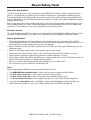
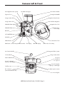
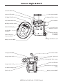
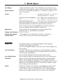
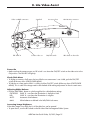
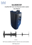
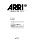
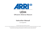
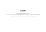
ARRICAM Lite
Quick Guide
About/Safety/Tools ........................................................2
Camera Left & Front........................................................3
Camera Right & Back .....................................................4
Camera Top & Bottom.....................................................5
1.
2.
3.
4.
5.
6.
7.
8.
9.
Quick Specs ..............................................6
Status Indicators .......................................7
Magazine Configurations ..........................8
Loading Lite Magazines ............................9
Threading ...............................................11
Power On, RUN, Inching, Gate Check......13
Changing Fps & Shutter ..........................14
Lite Video Assist......................................15
Arri Group Addresses .............................17
10/2001
About/Safety/Tools
About This Quick Guide
This Quick Guide provides a short introduction to the ARRICAM Lite camera. It does not replace the user’s
guide. It is essential that you acquaint yourself with the respective user’s guide before operating the gear.
Even though all efforts have been made to ensure the accuracy of this guide, changes and upgrades to the
products described can result in different hardware or behavior. In other words, technical data are subject to
change without notice.
Best viewing and printing of the Acrobat (pdf) version of this Quick Guide can be achieved through the use
of the Acrobat Reader 3.0 or later. The Acrobat Reader can be downloaded for free from the Adobe web
site at http://www.adobe.com. Use a PostScript printer for best printing results.
Software Version
This guide describes the ARRICAM system as of software packet “ACSWPack02”. Different software versions
can result in different behavior. Any ARRI service center can check and update the ARRICAM software.
Safety Specifications
• The Studio Viewfinder arm can be angled away from the camera to clear top loaded 300 m (1000’)
Studio magazines. When this is done, make sure to securely hold the eyepiece or eyepiece extension, as it
could otherwise swing out rapidly and cause pain and damage.
• Repairs should be carried out only by authorized service centers. Use only original ARRI accessories and
replacement parts.
• Never run the camera without a lens or a protective cap in the lens mount.
• Never place your hand in the lens cavity or the inside of the camera while the camera is running!
• Never open the movement or gate locking mechanism while the camera is running!
• Clean optical surfaces only with an optical brush or a clean optical cloth. In cases of solid dirt, moisten an
optical cloth with pure alcohol or a brand-name lens cleaner.
• Do not use solvents when cleaning the film path, plexiglass parts or rubber seals.
• Do not remove any screws which are secured with paint.
Tools
Anyone operating the ARRICAM cameras should have these five tools:
1.
2.
3.
4.
5.
The ARRICAM Ground glass tool is used to remove the ground glass and the field lens.
A 3 mm metric hex key is used to attach or remove most accessories.
A 5 mm metric hex key is used to remove the camera handles from the cubes.
A 1.5 mm metric hex key is used to adjust the video assist chip or the frameglow alignment.
A straight slot screwdriver with a wide blade is used to attach Bridgeplates and the Shoulder Set.
Please note that screwdrivers with a short, stubby shaft will not work with the Shoulder Set.
ARRICAM Lite Quick Guide, 10/2001, Page 2
Camera Left & Front
Lite Integrated Video System
Lite Mask Frameglow
Lite Camera Handle
Frameglow DIMMER
Eyepiece focus
Image rotation knob
Magazine release button
Image rotation lock
Lite Shoulder Magazine
EXPOSED FILM display
Magazine door lock
EXPOSED FILM reset
Magazine door
lock safety
BAT LED
SET SHUTTER button
RUN LED
Camera door lock
PHASE button
RUN button
SET FPS pushwheel switches
FPS display
SHUTTER display
Camera door lock safety
Lite Camera Handle
Lite Integrated Video System
Image rotation knob
Lite Viewfinder
PL mount
1 = normal 35
2 = super 35
DUST CHECK button
Power for Heated
Eyecup or Worklight
Power for Heated
Eyecup or Work light
Field lens
Lens Data System contacts
RS connectors
(remote RUN & 24 V dc)
Ground glass
ARRICAM Lite Quick Guide, 10/2001, Page 3
Camera Right & Back
Camera handle locks
Power on/off switch
Lite Camera Handle
SET RAW STOCK button
Lite Integrated Video System
SET/SHOW ASA button
Lite Viewfinder
PRESET pushwheel switches
RAW STOCK display
Cover for Lens
Data Box connector
Lite Shoulder
Magazine
RS connectors
(remote RUN
& 24 V dc)
Camera Accessory
Connector (CAC)
Handgrip attachment rosette
Battery connector (BAT)
Frameglow DIMMER
Lite Camera Handle
Image rotation knob
Tape hooks
Lite Integrated Video System
Power on/off switch
Image rotation lock
Camera Accessory Connector
(CAC)
Lite Mask Frameglow
Tape hook
Battery connector (BAT)
ARRICAM Lite Quick Guide, 10/2001, Page 4
Camera Top & Bottom
Lite Integrated Video System
Frameglow DIMMER
Lite Mask Frameglow
Camera handle locks
Tape hook
Eyepiece focus
Image rotation knob
Accessory shoes
Contrast filter lever
Sliding door for Power
Bridgeplate connector
Image rotation lock
Eyepiece focus
Hole for Shoulder Set locating pin
3/8-16 mounting holes
Shoulder Set mounting hole
ARRICAM Lite Quick Guide, 10/2001, Page 5
1. Quick Specs
Fps Range:
1.000 to 40.000 fps forward, 1.000 to 32.000 fps reverse. Reverse is only
possible with Studio magazines, and can only be set by the Speed Control Box.
Mirror Shutter:
0° to 180.0°, electronically adjustable in 0.1° increments. For ramps 11.2° to
180.0° can be used.
Power:
BAT: .................................................nominal 24 V dc in (Pin 1 is -, pin 2 is +)
Input power range: 16 - 35 V dc.
RS (camera & Power Bridgeplate): .....Pin 1: GND, pin 2: nominal 24 V dc out
CAC ................................................Pin 1: GND, pin 2: nominal 24 V dc out
Work Light/Heated Eyepiece: ............Outer: GND, inner: nominal 24 V dc out
All RS & CAC together can supply max. 2.5 amp continuously. Each Work
Light/Heated Eyepiece connector can supply 0.75 amp continuously.
The RS connectors on the Power Bridgeplate have only 24V output but no
remote run capability, like the camera RS connectors do.
Movement:
5-link movement with two registration pins and two transport claws.
Movements with 4 or 3 perf pulldown are available
Flange Focal Distance: 51.98 - 51.97 mm
Temperature Range:
+14° Fahrenheit to +104° Fahrenheit (-10°Celsius to +40°Celsius)
Contrast Filter:
A ND 0.6 filter can be moved into the viewfinder light path.
Accessories:
Magazines:
Lite Shoulder Magazine, Lite Steadicam Magazine, Studio Magazine
120/400, Studio Magazine 300/1000.
Note: The Lite Magazine Adapter is necessary to mount Studio magazines on
the Lite camera.
Lite Viewfinder:
2” and 6.6” Video Monitors, Lite Extension, Lite LCD Frameglow, Lite Mask
Frameglow with exchangeable masks, Lite Integrated Video System (IVS), Lite
100% Video Top, Heated Eyecup.
Note: the Studio Viewfinder can also be used on the Lite camera.
Lens Data System:
Lite Lens Data Box (LDB), Lens Data Display (LDD), LDS zoom & prime lenses.
Electronic:
Speed Control Box (SCB), Manual Control Box (MCB), In-camera Slate Box
(ISB), In-camera Slate Recording Module, Wireless Handgrip Attachment
(WHA-2), Power Bridgeplate, Worklight, Lens Control System CLM-1 & ZMU-1,
Wireless Lens Control System (WLCS), Iris Control Unit for speed/iris ramps
(ICU-1), Remote on/off switch (RS-4).
Other:
Shoulder Set, Steadicam Low Mode Set, exchangeable ground glasses and
format masks, PL mount zoom and prime lenses, Shift & Tilt Lens system,
various matte box systems, various follow focus systems, right side handgrip,
batteries, power supply, Arrihead II, Varicon contrast control, Obie light.
ARRICAM Lite Quick Guide, 10/2001, Page 6
2. Status Indicators
FPS Display Messages
The FPS display usually shows the current camera speed. If the camera needs to communicate something
important, status messages are displayed one at a time, with the most important one masking the less
important one(s).
!SW! At least two components have incompatible software. The camera will not run. Remove accessories
and restart the camera to see where the incompatibility resides.
0.0
During Standby: The camera’s built-in control panel controls fps.
Bat
During run: The camera continues to run. Change battery once the camera is stopped!
During standby: Power input is too low. The camera cannot be started. Change battery!
Bukl The red buckle trip flag and/or one or two of the sprocket guide sensors have been tripped. The
camera will not run.
FPS! A speed below or above the available fps range has been preset.
Hbat Incoming voltage equals or is larger than 35V. Magazine and accessory power will be switched off.
Heat The camera and magazine heaters are on. When camera runs, heaters are automatically turned off.
Jam The amount of film leaving and entering the magazine is different.
M/S! During run: The mirror shutter and the movement have lost synchronization. The camera will stop.
Mag (flashes) Magazine error. Try another magazine.
MCB The Manual Control Box controls fps. “-MCB” is shown when a reverse speed is set.
Movm The movement block is not fully closed.
Out
The camera ran out of film. To reset, take the magazine off or turn the camera off and on again.
Rev! Reverse run not possible. This is the case if a Lite magazine is attached. Camera cannot be started.
SCB The Speed Control Box controls fps. “-SCB” is shown when a reverse speed is set.
TkUp (flashes) The magazine feed side has tension, but the take-up side runs free. Reload the magazine.
Updt Software update in progress. The camera will not run until the update is completed.
Wind The magazine is winding up loose film. The camera will be ready once that is finished.
Shutter Display Messages
The shutter display usually shows the current shutter angle.
Err
ISB0
MCB
SCB
The preset shutter value does not equal the current shutter. See an ARRI service facility.
The camera is running up or down, and the shutter has been set to 0° while In-camera Slate
information is being exposed.
The SET button on the camera control panel has been pushed while the Manual Control Box
controls the shutter. Turn the Manual Control Box MANUAL CONTROL switch OFF and try again.
The SET button on the camera control panel has been pushed while the Speed Control Box controls
the shutter. Turn the Speed Control Box COMPENSATION switch OFF and try again.
Other Messages
The Lens Data Display and the SYSTEM LINE of the Integrated Video System will also display similar status
messages.
ARRICAM Lite Quick Guide, 10/2001, Page 7
3. Magazine Configurations
Studio Magazine
120/400
Studio Magazine
300/1000
Lite Magazine Adapter
Lite Camera
Lite Shoulder Magazine
Lite Steadicam Magazine
Two Lite magazines and two Studio magazines can be used on the Lite camera. Studio magazines run
forward and reverse, Lite magazines only forward. Lite magazines can be mounted on the Lite camera
without any adapters. To mount the Studio magazines on the Lite camera use the Lite Magazine Adapter. All
magazines can only be mounted in the back load position.
Note: When using the Lite Magazine Adapter, make sure to attach all three screws to the camera body in
the order shown below.
Screw 1
Screw 2
Lite Magazine Adapter
Screw 3
ARRICAM Lite Quick Guide, 10/2001, Page 8
4. Loading Lite Magazines
Always make sure that a loop protector is on the magazine when it is not on the camera. Always make sure
that the magazine opening cover is on the camera when no magazine is attached. The following instructions
pertain to Lite Shoulder and Steadicam magazines.
Step 1: The Feed Side
Load unexposed film only in absolute dark (dark room or
changing bag). Ensure that an empty film core is on the take-up
core holder before starting the loading procedure.
• Push the magazine door lock safety button towards the
magazine throat, lift the door lock and turn it counter-clockwise.
Open the door.
• Push the take-up core holder all the way to the magazine edge
(see picture to the right).
• Remove the film from the film can.
• Remove the tape from the film head. Make sure that the tape is
completely removed and secured.
• Place the film roll on the magazine door (see picture below).
Film
Film core
Feed side release button
Take-up release button
Take-up core holder
Feed side core holder
Magazine throat
Film head
• Push the film head into the left slit on the magazine throat from the inside (see picture above) and push it
through until it emerges on the outside of the magazine throat.
Note: When attaching a film core to a core holder, you should hear three clicks as described below.
• Push the feed side release button (first click).
• Place the film on the feed side core holder and push the film core down as far as it will go. Triggered by
the core pushing on the core holder key, the core holder clamps onto the core (second click).
Note: If you do not hear the second click, it is possible that the core holder key slipped into the core’s key
slot, and thus did not get clamped down securely. Lift the film up from the core holder, rotate it and
push down again.
Note: When placing film on the feed side core holder, don’t press on the film itself, as it could become
conical.
ARRICAM Lite Quick Guide, 10/2001, Page 9
• Hold the core holder stationary with one hand (you can grab it at its edges), and use the other hand to pull
the film out of the magazine. Do this until the core holder key engages into the film core’s key slot (third
click). Failure to do so can lead to film jams.
Step 2: The Take-up Side
• Push the film head gently into the right slit on the
magazine throat until it emerges inside the
magazine.
• Place the film into the core slot as shown below.
Note: Do not fold the film head over. In an active
displacement magazine the film always
Film core
pushes against a roller to move the core
holders. The smallest bump in the film roll
could lead to noise and other problems.
Magazine throat
Film loop
Note: The film head should not stick out above the
film core, as this could lead to jams!
• Rotate the take-up core clockwise 4 to 5 times until some film is firmly wound up.
• Close the magazine door. Make sure that the film is not caught in the door. Turn the magazine door lock
clockwise and flip it back into its recess.
• Pull up on the magazine door to double check that it is properly locked.
Step 3: Set RAW STOCK and ASA
• Enter the amount of raw stock loaded with the PRESET pushwheel switches.
• Push the SET RAW STOCK button until you see the number from the PRESET pushwheel switches appear in
the RAW STOCK display.
Note: When using the ARRICAM In-camera Slate, ASA also needs to be entered.
• Enter the ASA number of the film loaded with the PRESET pushwheel switches.
• Push the SET/SHOW ASA button until you see the number from the PRESET pushwheel switches appear in
the RAW STOCK display.
Note: The RAW STOCK display normally shows the amount of raw stock left in the magazine. To view the
currently set ASA, push the SET/SHOW ASA button briefly.
ARRICAM Lite Quick Guide, 10/2001, Page 10
5. Threading
Attaching the Magazine to the Camera
• Push the camera door lock safety button towards the lens, lift the door lock and turn it counter-clockwise.
Open the camera door.
• Push the silver magazine release button down to remove the magazine opening cover.
• Rotate the movement locking lever clockwise to swing the movement away from the film gate.
• Push the upper and the lower sprocket guide release buttons.
• Pull some film out of the magazine until the loop is about one hand width long.
• From the side, push the magazine halfway into the dovetail guide on the camera.
• Place the film in the movement so that it lies between the sprocket guides and the sprocket rollers, and
between the movement and the film gate (see picture below).
• Now push the magazine into the camera as far as it will go.
Magazine release button
Upper sprocket guide release
Upper loop marking
Upper sprocket roller
Upper sprocket guide
Movement locking lever
Buckel trip flag
Inching knob
Lower sprocket guide
Lower sprocket roller
Lower sprocket guide release
Lower loop marking
Threading the Film
• Position the film on the lower sprocket roller so the sprockets engage the film perforations. Close the lower
sprocket roller guide by pushing it towards the sprocket roller. Repeat for the upper sprocket roller.
Note: If you cannot easily close a sprocket guide, the sprockets probably do not engage the film
perforation properly. Open the sprocket guide and reposition the film. Never force a sprocket guide!
• Rotate the inching knob so the index point is at 12:00 o’clock.
• Place a finger of one hand on the film, just below the gate. With the other hand rotate the movement
locking lever counter-clockwise to slide the movement towards the gate.
• When you feel the transport claws touch the film, slide the film a little up and down to ensure that the
transport claws engage the film perforations. Then fully close the movement by rotating the locking lever all
the way counter-clockwise.
• Now rotate the inching knob so the index point is at 9:00 o’clock, the position labeled LOOP. Set the
upper and lower film loop to their markings by pushing down on the sprocket rollers and turning them.
ARRICAM Lite Quick Guide, 10/2001, Page 11
• To check for proper film transport, turn the inching knob clockwise. Then push the PHASE button.
Note: The FPS display will show the battery voltage when the PHASE button is pushed.
• Run the camera briefly at 24 or 25 fps to check for proper threading. With a little practice you will be able
to hear if there is any problem by the sound of film running through the camera at 24 or 25 fps.
• If you have the same film stock loaded that you will be using for the shoot, turn the PITCH adjustment with
a 3 mm hex key while the camera is running at 24 or 25 fps until you hear the least amount of noise.
Inching knob
FWD/REV adjustment
Pitch adjustment
• When the camera is set to run in reverse and b/w film is used, the best image quality can be achieved by
setting the FWD/REV adjustment to REV.
• Close the camera door.
Lite Magazine Adapter & Studio Magazine film path
Lite Shoulder Magazine film path
ARRICAM Lite Quick Guide, 10/2001, Page 12
6. Power On, RUN, Inching, Gate Check
Power On
The power on/off switch for the ARRICAM Lite is located at the back of the camera, above the CAC
connector. When a battery is attached and the power on/off switch is on, you should see characters appear
on the camera control panel displays.
Camera RUN
The big green RUN button is located on the left side of the camera. To run the camera, press the RUN button
briefly. To stop the camera, press the RUN button again.
The RUN LED is off while the camera is in standby. When the camera is started, it will glow red while the
camera is coming up to speed, and switch to green once the camera is running at the preset frame rate.
When the RUN button is pushed again to stop the camera, the LED will glow red while the camera slows
down, and turn off when the camera has stopped running.
Note: If the RUN LED glows red while the camera is in Standby, the camera is not ready and pushing the
RUN button will have no effect. The cause for this will be displayed in the FPS display (see “Status
Indicators”).
Inching
• To manually inch the camera, open the camera door and turn the inching knob clockwise. This will rotate
the movement only, not the mirror shutter.
Note: Any film in the camera body will be exposed to light when inching manually!
• To electronically inch the camera, hold the PHASE button down while the camera is in Standby.
Checking the Gate
• To check the gate, push the DUST CHECK button briefly. The shutter (not the movement) will rotate 180°.
• To move the shutter back into the viewing position, push the DUST CHECK button again briefly.
Camera control panel
SET
SHUTTER
RUN LED
FPS
PHASE button
PHASE
RUN
SET SHUTTER button
SHUTTER display
FPS display
SET FPS pushwheel switches
RUN button
ARRICAM Lite Quick Guide, 10/2001, Page 13
7. Changing Fps & Shutter
What Controls Fps?
When the camera is not running, the FPS display shows which item controls fps. If a minus sign preceds the
characters, the camera is set to run in reverse.
0.0
The camera’s built-in control panel controls fps.
SCB The Speed Control Box controls fps.
MCB The Manual Control Box controls fps.
ARRICAM Lite Speeds
The ARRICAM Lite can run from 1.000 to 40.000 fps forward, and from 1.000 to 32.000 fps in reverse. All
these speeds are crystal controlled. Reverse run is only possible with Studio magazines, not with Lite
magazines. Reverse speeds can be set only with the Speed Control Box. Whole number speeds (24, for
example) can be set with the camera control panel. Fractional speeds (23.976, for example) can be set with
the Speed Control Box.
Changing Fps on the Camera Control Panel
• If the Manual Control Box is connected, make sure that its MANUAL CONTROL switch is OFF.
• If the Speed Control Box is connected, make sure its SPEED CONTROL switch is OFF.
• Enter the desired speed with the SET FPS pushwheel switches on the camera control panel.
Changing Shutter Angle on the Camera Control Panel
Note: The ARRICAM mirror shutter can only be adjusted electronically. There is no manual shutter
adjustment mechanism.
• If the Manual Control Box is attached, make sure that the MANUAL CONTROL switch is set to OFF or FPS.
• If the Speed Control Box is attached, make sure that the COMPENSATION switch is set to OFF or IRIS.
• Push the SET SHUTTER button with a thin tool or pen. Each push will step through the following values:
11.2°, 22.5°, 30°, 45°, 60°, 75°, 90°, 105°, 120°, 135°, 144°, 150°, 172,8°, 180°.
Camera control panel
SET
SHUTTER
SET SHUTTER button
FPS
PHASE
RUN
FPS display
SET FPS pushwheel switches
ARRICAM Lite Quick Guide, 10/2001, Page 14
8. Lite Video Assist
Video out BNC connectors
EXT SYNC in
Jogwheel
S-Video video out
Accessory shoe
ON/OFF switch
Mini Monitor connector
IRIS wheel on other side
Power On
• Make sure that the camera power on/off switch is on. Move the ON/OFF switch on the video assist to the
ON position. The ON LED will light up.
Check/Hide Menu
• To display a summary of all menu choices while the on-screen menu is not visible, push the ON/OFF
switch all the way down (CHECK/HIDE MENU).
• To hide the on-screen menu while it is visible, push the ON/OFF switch all the way down (CHECK/HIDE
MENU). This is useful if the image needs to be checked while making adjustments in the on-screen menu.
Adjusting White Balance
• Push the WHITE BAL. button to cycle through the four white balance settings:
OUTDOOR 5600° K - use where the illumination is daylight or HMI.
IND.
3200° K - use where the illumination is tungsten.
AUTO
Automatic white balance.
MAN.
White balance as defined in the WB/GAIN sub-menu.
Increasing Image Brightness
If the video image is too dark, the iris of the video lens can be opened.
• To open the iris, turn the IRIS wheel on the left side of the Lite Integrated Video System.
ARRICAM Lite Quick Guide, 10/2001, Page 15
Manual Gain Control (MGC)
Gain is the electronic amplification of the video signal. Higher gain provides a brighter image but also
increases video noise. Therefore it is preferable to first open the iris if the video image is too dark.
Since the automatic gain control averages the image brightness, in some lighting situations (strong backlight,
for instance) manual gain control will yield a better video image.
• Push the MGC button to toggle between manual gain control (MGC LED on) and automatic gain control
(MGC LED off).
• When MGC is on, rotate (don’t push in) the jogwheel clockwise to increase or counter-clockwise to
decrease gain.
The On-screen Menu
The on-screen menu allows for adjustment of the following features: manual white balance, manual gain
control, video settings (including video shutter speeds), frame line inserter, frame store, text inserter (camera
status, system status, LDS info, timecode and more), VITC/white line.
• To display the main menu, push the jogwheel for 3 seconds .
• To select a submenu, rotate the jogwheel. The left arrow indicates which submenu is selected.
• To enter the selected submenu, push the jogwheel.
• To go back to the MAIN MENU choose EXIT, which can be found at the bottom of each screen.
• To leave all menus push the jogwheel for 3 seconds.
BNC Mode
• Push the BNC MODE button to decide what signal will be output by the two video out BNC connectors:
- COMP.
Left BNC:
Right BNC:
composite video with on-screen data.
composite video without on-screen data.
- Y/C
Left BNC:
Right BNC:
Y (luminance) portion of the video, with on-screen data.
C (chrominance) portion of the video signal, with on-screen data
- Y/C
Left BNC:
Right BNC:
Y (luminance) portion of the video, without on-screen data.
C (chrominance) portion of the video signal, without on-screen data
How to Get B/W Video
• Push the BNC MODE button to Y/C
(on-screen data visible) or to Y/C
• Connect the video cable to the left video out BNC connectors (Y).
(on-screen data not visible).
How to Preview Motion Blur
When a fast moving object is filmed with a slow fps and a wide open shutter angle, the object will appear
blurred on film. This is called motion blur. The amount of motion blur generated by the combination of fps,
shutter angle and object movement can be previewed with the ARRICAM Integrated Video System.
• Remove the magazine from the camera to save film.
• Push the jogwheel three seconds to view the on-screen menu.
• In the VIDEO CONFIG. submenu, set FLICKERFREE to ON.
• In the VIDEO CONFIG. submenu, set EXPOSURE TIME to FILM.
• Push the jogwheel three seconds to exit the on-screen menu.
• Run the camera. You now see a close approximation of the motion blur that will be recorded on film.
Varying degrees of motion blur can be achieved by changing camera speed, shutter angle, lighting
contrast and the speed with which objects move through the image. Motion blur is most visible at slow
camera speeds and at wide open shutter angles (try for instance 6 fps and 180°).
ARRICAM Lite Quick Guide, 10/2001, Page 16
9. Arri Group Addresses
Canada:
ARRI Canada Limited
415 Horner Ave. Unit 11, Toronto, Ontario M8W 4W3, Canada
Voice phone: +416 255 3335, FAX: +416 255 3399
Email: [email protected]
Germany:
Arnold & Richter Cine Technik
Türkenstraße 89, D-80799 Munich, Germany
Voice phone: +49 (0)89 3809-0, FAX: +49 (0)89 3809-1244
Email: [email protected]
ARRI Camera Rental (Film Equipment Rental Germany)
Türkenstraße 89, D-80799 Munich, Germany
Voice phone: +49 (0)89 3809-1240, FAX: +49 (0)89 3809-1798
Email: [email protected]
England:
ARRI GB Ltd Sales & Service
1-3 Airlinks, Spitfire Way, Heston, Middlesex, TW5 9NR, England
Voice phone: +44 (0)181 848 8881, FAX: +44 (0)181 561 1312
Email: [email protected]
ARRI MEDIA (Camera Rental England)
4-5 Airlinks, Spitfire Way, Heston, Middlesex, TW5 9NR, England
Voice phone: +44 (0)181 573 2255, FAX: +44 (0)181 756 0592
Email: [email protected]
ARRI Lighting Rental
20A Airlinks, Spitfire Way, Heston, Middlesex TW5 9NR, England
Voice phone: +44 (0)181 561 6700, FAX: +44 (0)181 569 2539
Email: [email protected]
Italy:
ARRI Italia S.r.l., Head Office (Milan)
Viale Edison 318, 20099 Sesto San Giovanni (Milan), Italy
Voice phone: +39 (0)2 262 271 75, FAX: +39 (0)2 242 1692
Email: [email protected]
ARRI Italia S.r.l., Rome
Via Placanica 95, 00040 Morena (Rome), Italy
Voice phone: +39 (0)6 726 707 97, FAX: +39 (0)6 723 1541
USA:
ARRI Inc., East Coast
617 Route 303, Blauvelt, NY 10913-1109, USA
Voice phone: 845-353-1400, FAX: 845-425-1250
Email: [email protected]
ARRI Inc., West Coast
600 North Victory Blvd., Burbank, CA 91502-1639, USA
Voice phone: 818-841-7070, FAX: 818-848-4028
Email: [email protected]
CSC Camera Service Center (Film Equipment Rental USA)
619 West 54th St, New York, NY 10019, USA
Voice phone: 212-757-0906, FAX: 212-713-0075
Email: [email protected]
World Wide Web:
www.arri.com
ARRICAM Lite Quick Guide, 10/2001, Page 17