1
Genesis
Baxi Heating Ltd.
Installation – Page 17
Initial Preparation
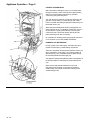
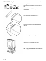
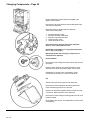
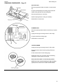
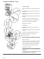
Remove the fixing template from the small carton.
After considering the site requirements (see page 13)
position the template on the wall.
Mark the position of the fixing holes for the two hooks. Use
the upper two holes where possible.
Mark the centre of the flue hole (rear exit). For side exit,
mark as shown. If required, mark the position of the gas and
water pipes. Remove the template.
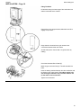
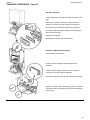
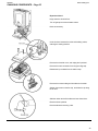
Cut the hole for the flue (minimum diameter 107mm).
Drill and plug the wall as previously marked. Secure the two
hooks to the wall.
Insert the two outer support bracket fixing screws, leaving
them sufficiently proud to engage in the keyhole slots.
GENESIS 96 ONLY
Before fixing the support bracket to the wall remove the blue
regulator unit from the inlet connection of the cold water
isolating valve. Replace with the red regulator supplied in
the contents kit (See page 41).
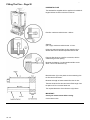
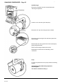
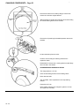
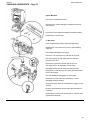
Attach the support bracket and ensuring it is level, secure to
the wall.
Insert the two inner screws.
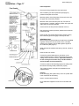
Connect the gas and water pipes to the valves on the
support bracket using the copper tails supplied. Ensure the
sealing washers are fitted correctly. (The rubber washer is
for use on the gas connection only. The fibre washers
are for the water circuit connections.)
Connect a pressure relief discharge pipe to the safety valve
tail routed to discharge safely outside the property.
The symbols for each connection are embossed on the
support bracket.
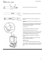
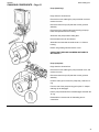
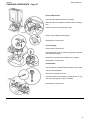
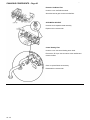
Flushing
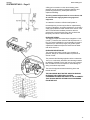
Flush thoroughly (see system notes). There is a plastic tube
in the contents kit to aid flushing.
Insert in to valve outlet as shown.
Fit the water filter supplied in the kit to the cold water inlet
valve.
17