1
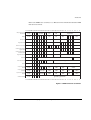
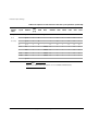
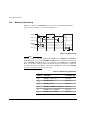
Signal Description
Table A-3 Signal Descriptions (continued)
Name
Type
Description
IR[3:0]
TAP controller instruction register
O4
Reflects the current instruction loaded into the TAP controller instruction
register. These bits change on the falling edge of TCK when the state
machine is in the UPDATE-IR state.
The instruction encoding is described in Public instructions on page B-9.
ISYNC
Synchronous interrupts
IC
Set this HIGH if nIRQ and nFIQ are synchronous to the processor
clock; LOW for asynchronous interrupts.
LOCK
Locked operation
O8
When the processor is performing a locked memory access this is HIGH.
This is used to prevent the memory controller allowing another device to
access the memory.
It is active only during the data swap (SWP) instruction.
This is one of the signals controlled by APE, ALE and ABE.
MAS[1:0]
Memory access size
O8
Used to indicate to the memory system the size of data transfer (byte,
halfword or word) required for both read and write cycles, become valid
before the falling edge of MCLK and remain valid until the rising edge
of MCLK during the memory cycle.
The binary values 00, 01, and 10 represent byte, halfword and word
respectively (11 is reserved).
This is one of the signals controlled by APE, ALE, and ABE.
MCLK
Memory clock input
IC
This is the main clock for all memory accesses and processor operations.
The clock speed can be reduced to allow access to slow peripherals or
memory.
Alternatively, the nWAIT can be used with a free-running MCLK to
achieve the same effect.
nCPI
Not coprocessor instruction
O4
LOW when a coprocessor instruction is processed. The processor then
waits for a response from the coprocessor on the CPA and CPB lines.
If CPA is HIGH when MCLK rises after a request has been initiated by
the processor, then the coprocessor handshake is aborted, and the
processor enters the undefined instruction trap.
If CPA is LOW at this time, then the processor will enters a busy-wait
period until CPB goes LOW before completing the coprocessor
handshake.
nENIN
NOT enable input
IC
This must be LOW for the data bus to be driven during write cycles.
Can be used in conjunction with nENOUT to control the data bus during
write cycles.
See Chapter 3 Memory Interface.
ARM DDI 0029G
Copyright © 1994-2001. All rights reserved.
A-7


![[U4.83.11] Opérateur POST_RCCM](http://vs1.manualzilla.com/store/data/006374258_1-02ec80959c2c4816a7bdfe94ffd80332-150x150.png)