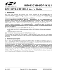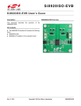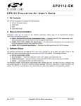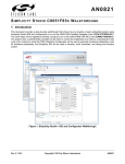
1
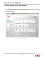
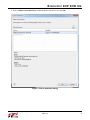
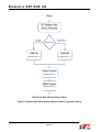
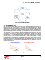
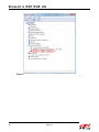
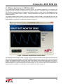
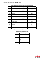
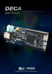
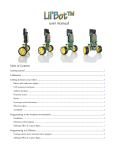
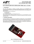
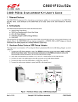
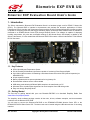
Biometric EXP EVB UG B I O ME T R I C EXP Evaluation Board U SER ’ S G UIDE 1. Introduction The Silicon Laboratories’ Biometric-EXP Evaluation Board is a hardware plugin card for EFM32™ Starter Kits (STK’s). The Biometric-EXP is intended to demonstrate and evaluate the biometric applications of Silicon Laboratories Si7013 Humidity and Temperature Sensor and the Si1146 Proximity/UV/Ambient Light Sensor which is capable of monitoring pulse rate and oxygen saturation (SpO2). A Biometric-EXP Software Demo is available to download to an EFM32 Wonder Gecko STK through Simplicity Studio. The software is capable of displaying humidity, temperature, UV, pulse rate, and SpO2 readings on the Wonder Gecko STK display. In addition to the Silicon Labs sensors, it is also notable that the Biometric-EXP EVB contains a Silicon Laboratories’ TS3310 Boost DC-DC Converter. Figure 1. EFM32 Wonder Gecko STK (Left) Connected to a Biometric-EXP (Right) 1.1. Key Features Si7013 Humidity and Temperature Sensor Proximity/UV/Ambient Light Sensor capable of monitoring Pulse Rate and SpO2 6-pin ribbon cable connector for attaching a wrist-based heart rate monitor EVB (ordered separately as HRM-GGG-PS) 20-pin expansion header Battery operated with low power optimizations for long battery life Demonstration software source code available USB debug mode allowing HRM and SpO2 samples to be transferred to a PC Windows GUI to visualize pulse signals and to record samples from USB debug mode Easy use through Simplicity Studio Si1146 1.2. Getting Started The first step to getting started with your new Biometric-EXP-EVB is to download Simplicity Studio from www.silabs.com/simplicity-studio. The simplicity studio software package contains all the tools, drivers, software examples, and documentation needed to use the Biometric-EXP-EVB. You will need to connect the Biometric-EXP-EVB to the EFM32WG-STK3800 Wonder Gecko STK or the EFM32GG-STK3700 Giant Gecko STK. The demo code can be loaded using the USB cable and the J-Link debug interface. Rev. 0.2 10/14 Copyright © 2014 by Silicon Laboratories Biometric EXP EVB UG Biometric EXP EVB UG 2. Loading the Demo onto the Gecko Starter Kit The following steps will load the demo firmware onto the Gecko STK. This process requires Simplicity Studio which is available for download at www.silabs.com/simplicity-studio. 1. Use a USB mini type cable to connect the J-Link debug interface on the Gecko STK to the PC and set the 3-position Power Source Select switch to DBG (right most position). 2. Launch Simplicity Studio. Figure 2. Simplicity Studio 2 Rev. 0.2 Biometric EXP EVB UG 3. Click on Detect Connected Device. Select the Gecko STK device, and click OK. Figure 3. Device Detection Dialog Rev. 0.2 3 Biometric EXP EVB UG 4. Click on the Demos button on the top right of Simplicity Studio. 5. Select the Biometric-EXP demo from the list and click Start. Figure 4. Demo Selection Dialog 4 Rev. 0.2 Biometric EXP EVB UG 3. Running the Demo A Silicon Labs EFM32 Wonder Gecko Starter Kit (EFM32WG-STK3800) and a Silicon Labs Biometric-EXP (see Figure 1) is needed to run the Biometric EXP Demo. The Biometric-EXP demo application uses the Wonder-Gecko STK’s LCD to display sensor output and the two push buttons, PB0 and PB1, to cycle through the modes of the demo. The full operation including startup is illustrated in Figures 5 and 6. 3.1. Demo Startup Upon reset, the demo will first check whether PB0 is pressed then store the result. It will then search for a supported device on the 6-pin ribbon cable connector. If a HRM-GGG-PS, Si1143-M01-PS or Si1147-M01-PS is detected, the demo will automatically use that device for HRM measurements. In this case, the Si1146 sensor onboard the Biometric-EXP will not be utilized. SpO2 is not available with either the HRM-GGG-PS or the Si114xM01-PS EVB's. Following the search for a ribbon cable device, the demo will check the stored value of PB0 to enable or disable the USB debug mode accordingly and display an USB On or USB Off message for 1 second. Refer to “4. USB Debug Mode” for details on USB debug mode. Lastly, the demo will display version information then start the demo in Heart Rate Monitor mode. Rev. 0.2 5 Biometric EXP EVB UG 5HVHW ,&5LEERQ&DEOH 'HYLFH'HWHFWLRQ 3UHVVHG 3%3UHVVHG" 1RW3UHVVHG 86%21 86%2)) 'LVSOD\HGIRUV 'LVSOD\HGIRUV 'HPR9HUVLRQ (Displayed for 1 s) +509HUVLRQ (Displayed for 1 s) 6WDUW+HDUW5DWH0RQLWRU'HPR0RGH Figure 5. Biometric-EXP Demo Startup Sequence Flash Programmer Dialog 6 Rev. 0.2 Biometric EXP EVB UG HeartRate Monitor (^i1146) 8OWUDYLROHW 6HQVRU 6L 6S2 0RQLWRU 6L 8VH3%DQG3% WRF\FOHWKURXJK PRGHVRIWKHGHPR 7HPSHUDWXUH 6HQVRU) 6L +XPLGLW\ 6HQVRU 6L 7HPSHUDWXUH 6HQVRU& 6L Figure 6. Biometric-EXP Demo Modes *Note: SpO2 Monitor mode is not available when using a HRM-GGG-PS, Si1143-M01-PS or Si1147-M01-PS. 3.2. Heart Rate Monitor Mode When heart rate monitor demo is idle, the LCD will show the word “Pulse” followed by a message instructing the user to place his/her finger on the optical sensor. In idle mode, the sensor is not continuously sampling. Rather, it executes one sample every two seconds by performing a forced measurement. That sample is then analyzed to determine if there is skin contact with the sensor. Only when the application detects skin contact does it begin sampling continuously and running the HRM algorithm. It will remain in run mode (continuous sampling) until skin contact is removed for greater than two seconds. This approach significantly reduces power usage when idle. When the application is acquiring the heart rate, it will display the word “Wait” on the LCD. It typically takes five to seven seconds to acquire a valid heart rate. Once a valid heart rate is measured, the display will show the heart rate. If the heart rate is not displayed within seven seconds, it is likely that the algorithm cannot get a valid pulse rate. When this occurs, the user should remove his/her finger and try it again adjusting the position of the finger and the finger pressure as needed. Proper finger position in relation to the sensor and LEDs as well as proper finger pressure is essential for accurate measurements. The finger should fully cover both LEDs and the sensor. As illustrated in Figure 7, the finger should be lightly placed on the sensor. Too much pressure will restrict blood flow in the finger and, therefore, not allow the sensor to measure a heart rate. Figure 7. Proper Finger Placement Rev. 0.2 7 Biometric EXP EVB UG 3.3. SpO2 Monitor Mode When SpO2 mode is active, the LCD will show “SpO2” followed by a message instructing the user to place his/her finger on the optical sensor. Beyond that, SpO2 monitor mode mirrors the operation of the Heart Rate Monitor mode as described in “3.2. Heart Rate Monitor Mode” . Please note that SpO2 mode is not available when using a HRM-GGG-PS, Si1143-M01-PS, or Si1147-M01-PS device via the 6-pin ribbon cable. Even more so than HRM, proper finger position and pressure is important to achieve a good SpO2 measurement. Refer to Figure 7 for an illustration of proper finger position. 3.4. Ultraviolet Sensor Mode When the UV sensor mode is active, the LCD will show “UV” followed by the measured UV index. In this mode, the UV reading is updated every two seconds. 3.5. Temperature Sensor Mode In the temperature sensor modes, the LCD will show the temperature in Fahrenheit or Celcius as indicated by an “F” or a “C” following the reading. In this mode the temperature reading is updated every two seconds. 3.6. Relative Humidity Sensor Mode In the relative humidity sensor mode, the LCD will show “RH” followed by the relative humidity reading. In this modem, the relative humidity reading is updated every two seconds. 8 Rev. 0.2 Biometric EXP EVB UG 4. USB Debug Mode The Biometric-EXP demo firmware includes a debug mode that enables Heart Rate Monitor and SpO2 raw samples from the sensor to be streamed to a host PC via the Gecko STK’s USB interface. Only HRM and SpO2 data is available via the USB debug interface. UV, Relative Humidity, and Temperature data is not available. Enabling and connecting to USB debug mode is illustrated in Figure 8 and is described in the following sections. The J-Link USB mini connector is not used for the Biometric-EXP demo debug interface. It is only used to load firmware and for firmware development To enable USB Debug Mode, hold down PB0 and press Reset. Continue holding PB0 until the display shows USB ON The Power Source Select Switch should be set to USB to enable the debug interface The USB micro connector is used as the Biometric-EXP demo debug interface. Figure 8. Enabling and Connecting to USB Debug Mode 4.1. Enabling USB Debug Mode In order to maintain power efficiency of the demo, the USB debug mode is disabled by default. The LCD will show “USB OFF” during startup. To enable USB debug mode, the user must hold down button PB0 then press and release the Reset button. Both buttons are on the Gecko STK as shown in Figure 8. The user should hold down PB0 until the LCD shows “USB ON.” At this point, USB is enabled and the demo will run normally. To later disable USB debug mode the user can press the Reset button without holding PB0. 4.2. Connecting to USB Debug Mode on a PC Prior to using USB debug mode, the user must first install the Biometric-EXP Windows Evaluation Software. This will install the Windows applications and drivers necessary to use USB debug mode. The Gecko STK has two USB type connectors: a USB Mini type connector labeled J-Link on the short side of the EVB and a USB Micro type connector on the long side of the EVB. The USB Micro connector is used for the USB debug interface, as shown in Figure 8. In addition to using the correct physical interface, the Power Source Select switch must be set to USB (center position) for proper operation. USB debug mode utilizes a Virtual COM Port (VCP) interface to communicate between the Biometric-EXP demo and the PC. With the Windows software installed, USB debug mode enabled on the Wonder Gecko and a USB cable connecting the Wonder Gecko STK and the PC, the device will appear in Windows Device Manager as a COM port as shown in Figure 9. Rev. 0.2 9 Biometric EXP EVB UG Figure 9. Biometric-EXP Virtual COM Port Device in Windows Device Manager 10 Rev. 0.2 Biometric EXP EVB UG 4.3. Windows Applications for USB Debug Mode The Biometric-EXP Windows Evaluation Software includes two Windows applications for evaluating and debugging the Biometric-EXP Heart Rate Monitor and SpO2 functions. An installation program for the BiometricEXP Windows Evaluation Software is distributed with Simplicity Studio. It can be found in the Installers directory within the Simplicity Studio directory structure. Following installation, the software can be launched from the Windows Start menu. The Windows Graphical User Interface (GUI) demo provides a waveform display of the HRM data along with the HRM and SpO2 calculated values. The GUI demo also allows the user to record the streaming data to a file for further analysis. A screenshot of the GUI demo is shown in Figure 10. Figure 10. Windows Graphical User Interface Demo The Windows Console Demo provides a running, once-per-second text output of many parameters that are used within the HRM and SpO2 algorithms including the HRM and SpO2 results. This tool can be used for advanced analysis of the HRM and SpO2 streaming data; however, the details of the parameters and how to use them to analyze a HRM-SpO2 recording is beyond the scope of this document. Refer to the HRM-SpO2 API Reference Manual available from Silicon Laboratories for further details. The C++ source code of the Console Demo is supplied within the installation. A screen shot of the Console demo is show in Figure 11. Rev. 0.2 11 Biometric EXP EVB UG Figure 11. Windows Console Demo To connect the console to the streaming output from the Biometric-EXP, the user can type –u COMx <filename> at the prompt. In this command, COMx is the VCP COM port as shown in Figure 9, and the optional input <filename> specifies the file in which the streaming data is to be stored. Note that if <filename> is not provided, the console automatically stores the data to a default file. This default file is overwritten each time the demo is run. The console also has the ability to playback recorded files. This is done by typing –f filename at the prompt. In this command, filename specifies the source file containing the saved recording. It is important to note that the USB debug interface is a one-way interface. Therefore, the applications can only take the streaming data as an input. They do not allow the user to control the Biometric-EXP software. 12 Rev. 0.2 Biometric EXP EVB UG 5. Hardware Overview 5.1. Block Diagram Vmcu EXP Connector (JP3) EXP Connector (JP4) All other lines TS3310 DC-DC Boost Converter I2C Ribbon Connector (J6) 5V I2C2 Red I2C1 Si1146 Proximity/ UV/Ambient Light Sensor IR Si7013 Humidity & Temperature Sensor Figure 12. Biometric-EXP Block Diagram 5.2. Hardware Connectors As illustrated in Figure 12 there are two separate I2C buses implemented on this board. The Si1146 is on its own bus while the Si7013 and the I2C Ribbon Connector J6 are on the second bus. This allows for expansion boards designed for the I2C Ribbon Connector to connect to the Biometric-EXP without the possibility of an I2C slave address conflict between any potential Si1145/Si1146/Si1147 devices on the expansion board. Table 1 details the pinouts and signal function of the Biometric-EXP connectors JP3 and JP4. Table 1. Expansion Connectors (JP3 and JP4) Pin # Biometric-EXP Signal Description WonderGecko Signal 1 GND GND 2 VMCU 3 Red LED D3 PC0 4 Not Used PD0 5 Green LED D3 PC3 6 Not Used PD1 7 Si7013 and I2C Ribbon Connector (J6) SDA PC4 VMCU Rev. 0.2 13 Biometric EXP EVB UG Table 1. Expansion Connectors (JP3 and JP4) (Continued) Pin # Biometric-EXP Signal Description WonderGecko Signal 8 Not Used PD2 9 Si7013 and I2C Ribbon Connector (J6) SCL PC5 10 Not Used PD3 11 Not Used PB11 12 Enable TS3310 Boost DC-DC Converter PD4 13 Not Used PB12 14 Si1146 and I2C Ribbon Connector (J6) INT PD5 15 Not Used PC6 16 Si1146 I2C SDA PD6 17 Si1146 I2C SCL PD7 18 Not Used 5V 19 Not Used GND 20 3.3 V 3.3 V Table 2 details the pinouts and signal descriptions of the 6-pin I2C connector J6. Table 2. 6-Pin I2C Connector (J6) Pin # 14 Signal Description 1 I2C SCL 2 5V 3 I2C SDA 4 GND 5 INT 6 VMCU Rev. 0.2 Biometric EXP EVB UG 5.3. Hardware Component Layout IR and Red LEDs Si1146 Proximity/UV/Ambient Light Silabs TS3310 DC-DC Boost Converter Si7013 Humidity & Temperature EXP connector for EFM32 STK I2C Ribbon Cable Connector Figure 13. Biometric-EXP Hardware Component Layout -/LQN'HYHORSPHQW ,QWHUIDFH /&' 5HVHW%XWWRQ (;3+HDGHU &RLQ&HOO %DWWHU\ 3RZHU6RXUFH 6HOHFW ()0:RQGHU *HFNR 0&8 %XWWRQ3% 86%'HEXJ,QWHUIDFH %XWWRQ3% Figure 14. Wonder Gecko STK Component Layout Rev. 0.2 15 Biometric EXP EVB UG 5.4. Schematics, Assembly Drawings, and BOM The schematics, assembly drawings and bill of materials (BOM) for the Biometric-EXP-EVB are available through simplicity studio when the EXP documentation package has been installed. 16 Rev. 0.2 Biometric EXP EVB UG DOCUMENT CHANGE LIST Revision 0.1 to Revision 0.2 Added "1.2. Getting Started" on page 1. Modified “2. Loading the Demo onto the Gecko Starter Kit” to describe how to load the demo that is integrated into Simplicity Studio Added a comment in“3.2. Heart Rate Monitor Mode” describing the proper finger pressure. Added Figure 8, “Enabling and Connecting to USB Debug Mode,” on page 9. Added a comment in “4.3. Windows Applications for USB Debug Mode” describing where to find the Windows software installation program within Simplicity Studio Removed the section describing how to import the project source into Simplicity Studio. It is now integrated and imports seamlessly Removed the schematic as it is now a separate document in Simplicity Studio. Rev. 0.2 17 Biometric EXP EVB UG CONTACT INFORMATION Silicon Laboratories Inc. 400 West Cesar Chavez Austin, TX 78701 Tel: 1+(512) 416-8500 Fax: 1+(512) 416-9669 Toll Free: 1+(877) 444-3032 Please visit the Silicon Labs Technical Support web page: https://www.siliconlabs.com/support/pages/contacttechnicalsupport.aspx and register to submit a technical support request. Patent Notice Silicon Labs invests in research and development to help our customers differentiate in the market with innovative low-power, small size, analogintensive mixed-signal solutions. Silicon Labs' extensive patent portfolio is a testament to our unique approach and world-class engineering team. The information in this document is believed to be accurate in all respects at the time of publication but is subject to change without notice. Silicon Laboratories assumes no responsibility for errors and omissions, and disclaims responsibility for any consequences resulting from the use of information included herein. Additionally, Silicon Laboratories assumes no responsibility for the functioning of undescribed features or parameters. Silicon Laboratories reserves the right to make changes without further notice. Silicon Laboratories makes no warranty, representation or guarantee regarding the suitability of its products for any particular purpose, nor does Silicon Laboratories assume any liability arising out of the application or use of any product or circuit, and specifically disclaims any and all liability, including without limitation consequential or incidental damages. Silicon Laboratories products are not designed, intended, or authorized for use in applications intended to support or sustain life, or for any other application in which the failure of the Silicon Laboratories product could create a situation where personal injury or death may occur. Should Buyer purchase or use Silicon Laboratories products for any such unintended or unauthorized application, Buyer shall indemnify and hold Silicon Laboratories harmless against all claims and damages. Silicon Laboratories and Silicon Labs are trademarks of Silicon Laboratories Inc. Other products or brandnames mentioned herein are trademarks or registered trademarks of their respective holders. 18 Rev. 0.2