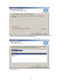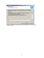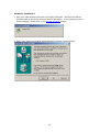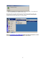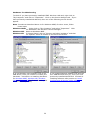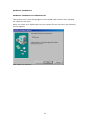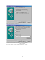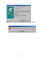
1
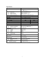
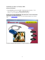
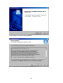
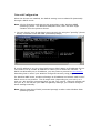
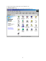
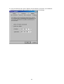
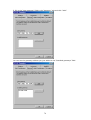
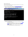
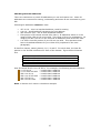
Wireless USB Adapter
User Manual
1
Table of Contents
Trademarks.......................................................................................................................... 4
Introduction...................................................................................................................... 5
Check list..................................................................................................................... 6
System Requirements.................................................................................................. 6
Specification .................................................................................................................... 7
Radio Channel Selection Table................................................................................... 8
Wireless LAN Technology Overview....................................................................... 9
Technology overview.................................................................................................. 9
Features and benefits................................................................................................... 9
Application.................................................................................................................. 9
Installation procedure for Windows 98SE ............................................................. 11
Software Installation ................................................................................................. 11
Hardware Installation ................................................................................................ 17
Installation procedure for Windows 2000 .............................................................. 20
Software Installation ................................................................................................. 20
Hardware Installation ................................................................................................ 26
Installation Procedure for Windows ME ................................................................ 28
Software Installation ................................................................................................. 28
Hardware Installation ................................................................................................ 34
Installation Procedure for Windows XP ................................................................. 36
Software Installation ................................................................................................. 36
Hardware Installation ................................................................................................ 36
Installing Configuration and Monitor Utility Program ....................................... 40
Configuring Your WLAN Card (for Windows 98SE/2000/ME) ..................... 46
Monitor Tab .............................................................................................................. 47
Operating Mode Selection ................................................................................ 49
Channel Selection ............................................................................................. 50
Selecting SSID .................................................................................................. 51
Setting the Transmission Rate........................................................................... 52
Selecting Power Management Modes............................................................... 53
Statistics Tab ............................................................................................................. 54
Site Survey Tab ......................................................................................................... 55
Encryption Tab.......................................................................................................... 56
Selecting the Encryption Type .......................................................................... 57
Setting the Encryption Keys ............................................................................. 58
Choosing the Encryption Key to Use................................................................ 59
Selecting WEP Mode ........................................................................................ 60
Setting the Authentication Type ....................................................................... 61
Advanced Tab ........................................................................................................... 62
Version Tab............................................................................................................... 63
Configuring Your WLAN Card (for Windows XP) ............................................ 64
Network Configuration ............................................................................................... 66
Using PING Command ............................................................................................... 74
2
Tutorial ............................................................................................................................ 76
Infrastructure and Ad-hoc modes.............................................................................. 77
Packet Fragmentation................................................................................................ 78
Encryption ................................................................................................................. 79
Authentication Type.......................................................................................... 80
How is encryption key generated? .................................................................... 80
Troubleshooting ............................................................................................................ 81
Step – by – Step Debugging...................................................................................... 82
Enabling Hardware Devices.............................................................................. 86
Disabling Hardware Devices............................................................................. 87
Problems using encryption................................................................................ 88
PING Troubleshooting .............................................................................................. 92
Checking Valid IP Addresses ................................................................................... 93
Hardware Troubleshooting ....................................................................................... 94
Hardware Installation ................................................................................................ 95
Hardware Installation for Windows 98SE ........................................................ 95
Hardware Installation for Windows 2000 ......................................................... 99
Hardware Installation for Windows ME ......................................................... 104
Hardware Re-installation ........................................................................................ 107
Hardware Re-installation for Windows 98SE................................................. 107
Hardware Re-installation for Windows 2000 ................................................. 109
Hardware Re-installation for Windows ME ................................................... 115
Hardware Re-installation for Windows XP .................................................... 118
FAQ ............................................................................................................................... 123
What is an Access Point (AP)? ............................................................................... 123
What is the difference between Infrastructure mode and Ad-hoc mode? ............... 123
What is the maximum transmission rate among WLAN cards? ............................. 123
What is Channel Selection? .................................................................................... 123
What OS can your driver support?.......................................................................... 123
Does the radio wave emitted from WLAN card have any threat to human health? 123
How can I remove the USB Wireless LAN Monitor Utility in Windows? ............ 124
How can I configure the USB Wireless LAN adapter in Windows XP?................ 124
Can I install USB Wireless LAN car via an USB hub? .......................................... 124
I don’t have any free USB port left, what can I do? ............................................... 124
Why do I experience delay when I am using Ad-Hoc mode? ................................. 124
Where is my Monitor and Utility icon? .................................................................. 124
Why did the monitor and utility icon turn red?....................................................... 124
Glossary ........................................................................................................................ 125
Federal Communications Commission Interference Statement ..................... 128
3
Copyright © 2002 All rights reserved.
The information in this document is subject to change without notice. The statements,
configurations, technical data, and recommendations in this document are believed to
be accurate and reliable, but are presented without express or implied warranty. Users
must take full responsibility for their applications of any products specified in this
document. The information in this document is proprietary to Manufacturer.
Manufacturer reserves the right to make revisions to this publication without obligation
to notify any person or entity of any such changes.
Trademarks
Microsoft, Windows 98SE, Windows ME, Windows 2000, Windows XP are
trademarks or registered trademarks of Microsoft Corporation.
Atmel and Atmel logo are trademarks or registered trademarks of Atmel Corporation.
All other trademarks and registered trademarks are the property of their respective
owners.
4
Introduction
USB wireless LAN adapter enables high-speed access without wires to network assets.
The adapter uses the IEEE802.11b protocol to enable communication between host
computer and other computers, using the 2.4Ghz ISM Radio band for the
communication medium. It enables true wireless communications between hosts,
LAN’s and the Internet. Users can enjoy the convenience of mobile computing without
any attached cables or wires.
Installation CD with Driver and Application utility program enables you to install our
adapter into your PC or laptop with ease. User manual and quick installation guide
provide a quick introduction to wireless LAN technology and its application.
5
Specification
Item
Feature
Network Interface
Support OS
Network Drivers
Network Protocol
Network Architecture
Host Interface
Roaming
Configuration & Management
Date Rate
Aggregate Throughput
DATA RATES DISTANCE RANGE
@ 11 Mbps
@ 5.5 Mbps
@ 2 Mbps
@ 1 Mbps
ANTENNA
Data Security
Radio Specification
Modulation Technique
Wireless LAN Standard
Frequency Range
Modulation
11Mbps
5.5Mbps
2Mpbs
1Mpbs
Power Consumption
Receive Mode
Transmit Mode
Led indicators
Safety and Regulation
Size & Weight
Dimensions (L/W/H)
Weight
Environmental
Operating Temperature
Operating Humidity
Specification
IEEE802.11b
USB 1.1
Wi-Fi Compliant
Windows 98SE/ME/2000/XP
NDIS 3 Or higher
TCP/IP, IPX, SPX, NETBUI
Supporting Ad-hoc and Infrastructure
USB type B
Full Mobility and seamless roaming
Diagnostics utility monitor and setup
1,2,5.5, 11Mbps per channel
6Mbps
Indoor Range (min.)
Outdoor Range (min.)
25m
100m
35m
120m
50m
140m
60m
150m
Internal
64/128bit WEP Encryption
Direct Sequence Spread Spectrum
Compliant with IEEE802.11B
2.4-2.4835 GHz
DQPSK (CCK)
DQPSK (CCK)
DQPSK
DBPSK
320mA
370mA
Red: Power on
Green: Activity
FCC part 15 subpart C Paragraph 15.247
CE, ETS 300 826
108.5mmx71.2mmx22mm
100g(W/O Package)
0-40 Degree Celsius
10%~90% non-condensing
7
Radio Channel Selection Table
Regulator domains
Channel
ID
Center
Frequency (MHz)
FCC
U.S.A
1
2412
2
2417
3
2422
4
2427
5
2432
6
2437
7
2442
8
2447
9
2452
10
2457
11
2462
12
2467
13
2472
14
2484
DOC
Canada
8
ETSI
Most of
Europe
MKK
Spain
France
Japan
Wireless LAN Technology Overview
Technology overview
A wireless local area network (LAN) is a flexible data communications system
implemented as an extension to, or as an alternative for, a wired LAN. Using radio
frequency (RF) technology, wireless LANs transmit and receive data over the air,
minimizing the need for wired connections. Thus, wireless LANs combine data
connectivity with user mobility.
Wireless LANs have gained strong popularity in a number of vertical markets,
including the health-care, retail, manufacturing, warehousing, and academia.
These industries have profited from the productivity gains of using hand-held
terminals and notebook computers to transmit real-time information to centralized
hosts for processing. Today wireless LANs is becoming more widely recognized as a
general-purpose connectivity alternative for a broad range of business customers
in home and office.
Features and benefits
Flexible and standards-based (IEEE802.11b) interoperability.
Mobile connectivity.
Support roaming protocol.
64/128 bits WEP key encryption for security.
Up to 11Mbps access to LAN or Internet.
Long range: The freedom to access real-time information anywhere,
anytime within a building or multi-building complex without wires.
Manageable: Installing a USB Wireless LAN is fast and easy.
Networked conference: Managers and employees can access the
network as they move from meeting to meeting, get up to date
information and the ability to communicate and make decisions ‘on the
run’.
Campus wide network mobility: Enterprise can set up easy to use
wireless networks that cover the entire campus transparently.
Economical: Wireless networks cut out the need to purchase expensive
network cables, saving you money and time to layout the cables.
Application
Healthcare: More and more healthcare professionals around the world
are taking advantage of the speed, mobility and flexibility of wireless
LAN solutions to increase the quality of patient care and reduce costs.
Hospitals can access patient information at bedside, monitor
pharmaceutical data and other information vital to quality of patient
care.
Hospitality and Retail: From hotels and casinos, to cruise lines and
rental car agencies, wireless technology provides the hospitality industry
a mobile service advantage, allowing workers access to real-time
information. Retail companies use products to provide mobile and
portable points-of-sale and in-store inventory tracking that simplify and
speed customer interactions.
Warehousing and Distribution: Handheld devices with barcode
readers monitor inventory and warehouse storage and shipment to
control warehousing costs and ensure speedy delivery of products.
Manufacturing: WLANs have helped manufacturing improve
productivity and speed with instant data access to monitor inventory,
track shipments and run production equipment.
9
Education: Wireless LANs in education offer a low-cost solution to highspeed Internet access with the flexibility to meet the needs of the everchanging educational landscape.
Finance: In the fast-paced world of finance, access to real-time
information is crucial. Financial traders employ wireless solutions to
receive up-to-the-minute pricing information and real-time data
anywhere on the trading floor.
10
Installation procedure for Windows 98SE
Software Installation
1. Insert DRIVER CD into your CD-ROM. Following screen will appear. If the
screen doesn’t appear, go to “Start” ⇒ “Run”, then type in
F:\autorun\autorun.exe
(where ‘F’ is your CD-ROM drive) and press the enter key.
DO NOT PLUG YOUR USB WIRELESS LAN CARD INTO YOUR SYSTEM UNTIL
THE DRIVER HAS BEEN INSTALLED.
Refer to the trouble shooting section if you have already plugged in your WLAN
card.
2. Click on “Windows 98SE Installation” to begin installation.
11
3. Click “Next” to continue with installation.
4. If you accept the License Agreement, click “Yes”.
12
5. Select “Application and USB Drivers” and click “Next”.
Note: You can choose Application only if you had previously uninstall your
application utility. If you are unsure whether you have previously installed
ATMEL USB Wireless LAN card, you should choose Application and USB
Drivers.
6. Click “Next” to continue.
13
7. Click on Browse button to choose a path to install the software utility and click
“Next”, or click on Next to accept default path.
8. Type a name to identify your Wireless LAN card, or click on Next to accept
default name.
14
9. Confirm installation settings and click “Next” to continue, or you can click Back
button to modify.
15
10. Window has finished installing. Click “Finish” to close this window.
Proceed to Hardware Installation to install your USB Wireless LAN card.
16
Hardware Installation
1. Plug your USB Wireless LAN card into a spare USB port. Windows will detect
Wireless LAN card and the following screen will appear.
2. Click “Next” to continue.
3. Click “Next” to specify the location of the driver.
17
4. Click the Specify a location check box and then type in the path:
F:\Driver\Win98
(where ‘F’ is your CD-ROM driver letter) and click “Next”.
Note: Make sure other two check boxes are not selected.
5. Window has located the driver information from your CD-ROM. Click “Next” to
continue.
18
6. Window has successfully installed your USB Wireless LAN card. Click on “Finish”
to finish installation.
7. You need to restart your computer before you can begin to use your USB
Wireless LAN card. After window re-boot, you can configure its settings via
“Configuration & Monitor Utility” located at “Start” ⇒ “Programs” ⇒ “ATMEL
802.11 Wireless LAN”.
Refer to Configuring Your WLAN Card section on how to configure and
setup your wireless LAN to your needs.
19
Installation procedure for Windows 2000
Software Installation
1. Insert DRIVER CD into your CD-ROM. Following screen will appear. If the
screen doesn’t appear, go to “Start” ⇒ “Run”, then type in
F:\autorun\autorun.exe
(where ‘F’ is your CD-ROM drive) and press the enter key.
DO NOT PLUG YOUR USB WIRELESS LAN CARD INTO YOUR SYSTEM UNTIL
THE DRIVER HAS BEEN INSTALLED.
Refer to the trouble shooting section if you have already plugged in your WLAN
card.
2. Click on “Windows 2000 Installation” to begin installation.
20
3. Click “Next” to continue with installation.
4. If you accept the License Agreement, click “Yes”.
21
5. Select “Application and USB Drivers” and click “Next”.
Note: You can choose Application only if you had previously uninstall your
application utility. If you are unsure whether you have previously installed
ATMEL USB Wireless LAN card, you should choose Application and USB
Drivers.
6. Click “Next” to continue.
22
7. Click on Browse button to choose a path to install the software utility and click
“Next”, or click on Next to accept default path.
8. Type a name to identify your Wireless LAN card, or click on Next to accept
default name.
23
9. Confirm installation settings and click “Next” to continue, or you can click Back
button to modify.
24
10. Window has finished installing. Click “Finish” to close this window.
Proceed to Hardware Installation to install your USB Wireless LAN card.
25
Hardware Installation
1. Plug your USB Wireless LAN card into a spare USB port. Windows will detect
Wireless LAN card and the following screen will appear. If the following screen
doesn’t appear, please refer to the trouble shooting section.
2. Click “Yes” when the Window digital signature request screen appears.
26
3. Window is installing the necessary files for your WLAN card. This window will
close automatically once window finishes setup.
Next time when you start windows, the Configuration and Monitor Utility will
automatically be loaded onto your task bar. You can start the utility program
straight away from the start menu, as shown below.
Refer to Configuring Your WLAN Card section for more information on how
to configure and setup your wireless LAN to your needs.
27
Installation Procedure for Windows ME
Software Installation
1. Insert DRIVER CD into your CD-ROM. Following screen will appear. If the
screen doesn’t appear, go to “Start” ⇒ “Run”, then type in
F:\autorun\autorun.exe
(where ‘F’ is your CD-ROM drive) and press the enter key.
Warning: DO NOT PLUG YOUR USB WIRELESS LAN CARD INTO YOUR
SYSTEM UNTIL THE DRIVER HAS BEEN INSTALLED.
Refer to the trouble shooting section if you have already plugged in your WLAN
card.
2. Click on “Windows ME Installation” to begin installation.
28
3. Click “Next” to continue with installation.
4. If you accept the License Agreement, click “Yes”.
29
5. Select “Application and USB Drivers” and click “Next”.
Note: You can choose Application only if you had previously uninstall your
application utility. If you are unsure whether you have previously installed
ATMEL USB Wireless LAN card, you should choose Application and USB
Drivers.
6. Click “Next” to continue.
30
7. Click on Browse button to choose a path to install the software utility and click
“Next”, or click on Next to accept default path.
8. Type a name to identify your Wireless LAN card, or click on Next to accept
default name.
31
9. Confirm installation settings and click “Next” to continue, or you can click Back
button to modify.
32
10. Window has finished installing. Click “Finish” to close this window.
Proceed to Hardware Installation to install your USB Wireless LAN card.
33
Hardware Installation
1. Plug your USB Wireless LAN card into a spare USB port. Windows will detect
Wireless LAN card and the following screen will appear.
2. Window will then install the necessary files to support your WLAN card. Please
wait till window finishes copying the required files.
34
3. You can start to use your WLAN card once window finishes copying the required
files into your system. You can configure your WLAN through Configuration and
Monitor Utility located in your Start menu as shown.
Note: Configuration and Monitor Utility will start automatically next time when you
boot your system up. The utility icon will be located on the task bar.
Refer to Configuring Your WLAN Card section for more information on how
to configure and setup your wireless LAN to your needs.
35
Installation Procedure for Windows XP
Software Installation
Configuration and Monitor Utility software is not required to be installed onto
Windows XP as Windows already has a more sophisticated software installed in it.
Hardware Installation
1. Plug your USB Wireless LAN card into a spare USB port. Windows will detect
Wireless LAN card and the following screen will appear.
2. Click “Next” to let Windows install the software for your WLAN automatically.
36
3. Choose the path:
F:\driver\winxp\netvusba.inf
and click “Next” to continue with installation.
4. Click “Continue Anyway” when the Windows compatibility screen appears.
37
5. Window is now backing up your current settings as a backup point. This can be
restored if you encounter any problems with your WLAN card.
6. Window is now copying the necessary files into your system.
38
7. Your WLAN card has been installed successfully. Click “Finish” to start using
your wireless LAN.
Refer to Configuring Your WLAN Card section for more information on how
to configure and setup your wireless LAN to your needs.
39
Installing Configuration and Monitor Utility Program
To install configuration and monitor utility, insert your driver CD that came with
your USB WLAN card. If the following screen doesn’t appear, go to “Start” ⇒
“Run”, then type in
F:\autorun\autorun.exe
(where ‘F’ is your CD-ROM drive) and press the enter key.
Note: You are only required to install your configuration and monitor
utility program if you have previously uninstall it.
2. Click on “Windows XX Installation” (where XX denotes your operating system
version) to begin installation.
40
3. Click “Next” to continue with installation.
4. If you accept the License Agreement, click “Yes”.
41
5. Select “Application Only” and click “Next”.
6. Click “Next” to continue.
42
7. Click on Browse button to choose a path to install the software utility and click
“Next”, or click on Next to accept default path.
8. Type a name to identify your Wireless LAN card, or click on Next to accept
default name.
43
9. Confirm installation settings and click “Next” to continue, or you can click Back
button to modify.
44
10. Window has finished installing. Click “Finish” to close this window.
You can then locate your utility program from the start menu. As shown below:
45
Configuring Your WLAN Card (for Windows 98SE/2000/ME)
This section describes on how you can configure your WLAN card to your needs.
Double click on Monitor and Utility icon (shown left) to pop up the
program, as shown below.
There are six tabs in the monitor utility. Each tab serves a different function.
Choose one of the topics below:
i)
Monitor – uses for selecting which host/AP to connect to
ii)
Statistics – uses for viewing statistical values like packet send and received
iii)
Site Survey – shows the available hosts/APs.
iv)
Encryption – allows user to set or disable use of WEP encryption
v)
Advanced – to set preamble, fragmentation threshold values.
vi)
Version – Shows the version of your driver, firmware and application.
46
Monitor Tab
In the monitor tab, you can adjust the operating mode, infrastructure or ad-hoc,
which channel that can be used, which host/AP (SSID) you want to connect to, the
transmission rate (Tx Rate) and power management mode. Each of the setting is
described below:
Operating mode selection
Channel selection
SSID selection
Setting the Transmission rate
Selecting power management.
•
MAC address specifies the physical hardware address of your ATMEL USB
Wireless LAN.
•
Status specifies the current status. Status can be either Scanning,
Associated, Association denied and Ready
Scanning – means you are not connected to any hosts/APs but your
WLAN is searching for a host/AP to connect to.
Associated – means that you are connected to an Access Point. The
ID of the AP that you are connected to is given by the BSSID.
Association denied – means that you are denied connection to the AP
that you want to connect to. Reason might be you have your
encryption enabled while the AP didn’t enable theirs, or vice versa.
47
Ready – means that you are connected to another host through adhoc mode.
•
Signal Strength specifies the strength of your radio signal. Closer you get
to the host/AP, the stronger the signal will be. Conversely, when you
move away from the host/AP that you are connected to or being
obstructed by a set of walls or ceilings, the signal strength will decrease.
•
Link Quality determines the volume of traffic in the network. Link quality
will be good if the traffic in the network is low. Conversely, link quality
will be less efficient if the amount of traffic in the network is sufficiently
high.
48
Operating Mode Selection
There are two kind of operating mode, infrastructure and ad-hoc. If you are
unfamiliar with the terms “infrastructure” and “ad-hoc”, you may want to refer to
the tutorial section for further explanations.
For infrastructure mode, you will need an access point to connect to the network.
For ad-hoc mode, all is required is another host running their WLAN card in ad-hoc
mode.
49
Channel Selection
You cannot change the channel selection if you are using infrastructure mode. The
utility program will choose the optimal channel for you when you are in
infrastructure mode.
If you are in ad-hoc mode, then you are required to select a channel. By clicking
on the channel field, you can then select channels from 1 to 14.
To communicate to your friends through ad-hoc mode, both you and your friends
must set it to the same channel.
Note: If a lot of hosts are communicating with the same channel, then you may
experience some lag. Refer to the effective bandwidth section in the FAQ for more
information on why this is the case.
50
Selecting SSID
Type the name of the remote host or access points you want to connect to in the
SSID field.
If you don’t know the name of the remote host/AP you want to connect to, an
easier alternative is by double clicking on the BSSID field in the site survey.
51
Setting the Transmission Rate
Tx rate or transmission rate is the rate that your WLAN will send out the data at.
Available rate to adjust are 1, 2, 5.5 and 11Mbps.
Reason for allowing adjusting the transmission rate is because when the traffic
through the network is heavy, you may want to reduce the transmission rate to
reduce the likelihood of data loss. On the other hand, if the network condition is in
a good shape, then you may want to adjust the transmission rate to maximum to
achieve optimum performance out of your wireless LAN card.
Note: WLAN can detect and adjust the transmission rate according to the network
condition, we recommend you to adjust transmission rate to automatic.
52
Selecting Power Management Modes
Setting power management to Power Save will enable your wireless LAN to be in
standby mode after a certain period of inactivity.
Putting your WLAN into sleep mode will reduce your electricity consumption (hence
reducing your electricity bill) and maximize the life of your WLAN card.
Your wireless LAN will become active again if there is data to be send or received.
In other word, power save mode acts like your monitors screen saver.
53
Statistics Tab
Statistics tab contains information about how many data packets have been send
and received.
•
Data packets: Specifies how many successful or unsuccessful data packets
have been send and received. An unsuccessful data packet means it failed
CRC checksum.
•
Management packets: Specifies how many successful or unsuccessful
management packets have been send and received. Management packets
include ICMP (e.g. PING) packets, data that contain encryptions that need
to be decrypted and more. An unsuccessful management packet means it
either failed CRC checksum or the data packet cannot be decrypted
correctly.
•
Rejected packets: Specifies how many successful or unsuccessful data or
management packets have been send and received. Rejected packet may
arise when your computer has set restrictions on which IP addresses you
can receive packets from (firewall). Your system will reject packets if it
detects unsolicited data packets.
54
Site Survey Tab
Site survey lists all the available hosts/APs that are within your transmitting range.
Site survey provides information such as channels they are using, signal strength
to that host/AP, whether they have enable encryption and whether they are using
infrastructure or ad-hoc mode.
You can refresh the list by clicking on the Re-scan button. By pressing the re-scan
button, it will scan and produce a list of all hosts and APs that are within the
transmission range of your WLAN.
If you double click on one of the BSSID of the hosts/APs, your WLAN card will try
to connect with that host/AP.
55
Encryption Tab
Encryption tab allows you to enable or disable the use of encryption when sending
or receiving data. Each of the setting is described below.
Selecting the Encryption Type
Setting the Encryption Keys
Choosing the Encryption Key to Use
Selecting WEP Mode
Setting the Authentication Type.
If you are unfamiliar with encryption and how encryption is created and used,
please refer to the tutorial section for further explanations.
56
Selecting the Encryption Type
Encryption field let you specify what encryption you want to use.
There are three types of encryption, 64 and 1281 bits encryption and disabled. No
encryption will be applied to data packets if the setting is being set to disabled.
Both encryption types use the same algorithm to encrypt and decrypt data.
Difference between these two types of encryption method is that 128bits
encryption takes slightly longer time to decode (but more secure) then 64 bits.
1
Some manuals specify 40 and 108 bits encryption. This is because the manual exclude 24 bits
Initializing Vector (IV).
57
Setting the Encryption Keys
For 64bits encryption, 10 hexadecimal digits must be inputted in each of the 4 keys.
26 hexadecimal digits must be supplied in each of the 4 fields if 128 bits encryption
is used.
Refer to the troubleshooting section if you have trouble in setting your keys.
58
Choosing the Encryption Key to Use
Choosing the key for encrypting and your data. When choosing the key to use,
make sure other hosts or access points that you are communicating with have the
same encryption value in the corresponding key number.
Refer to the troubleshooting section if you encounter problems when sending data
with the specified key.
59
Selecting WEP Mode
WEP mode let you specify whether other users have to have WEP enabled in order
to communicate with you.
Setting the mode to Mandatory means that every other host or APs have to enable
their WEP encryption in order for them to communicate with you. On the other
hand, setting WEP mode to Optional will enable other hosts and APs to
communicate with you regardless whether they have enabled their WEP encryption
or not.
60
Setting the Authentication Type
Authentication type determines which algorithm to be used to encrypt and decrypt
data packets. Refer to the tutorial section if you are not sure about how open and
shared key system work. Setting authentication type to automatic is highly
recommended.
61
Advanced Tab
Preamble helps to synchronize sender and receivers clocks and also help to identify
the start of data. Setting the preamble type to long help to synchronize the clocks
more accurately, but it takes up bandwidth. Setting preamble to automatic is
highly recommended.
Fragmentation threshold specify the maximum data size before the data is been
fragmented. Refer to the tutorial section on why we need to fragment data
packets.
Request To Send (RTS) and Clear To Send (CTS) specify the maximum data size
before a RTS management packet is send out to the network requesting for
temporal usage of the network. That is, the host will get temporal maximum
bandwidth available to the network.
Setting the value to maximum (2346 and 2347 respectively) will disable the setting.
62
Version Tab
Version tab provide information such as your driver, application and firmware
versions.
63
Configuring Your WLAN Card (for Windows XP)
This will give you a quick run down on how to configure and use your WLAN under
Windows XP operating system. For a more detail description, please refer to the
Windows XP reference materials.
Click on your network icon to open up the utility program.
Window will list a set of available networks. To connect, select on the name of the
network and click on the Connect button. Windows will advice you on whether you
have successfully connected to that network.
Note: The above screen may not appear if you have previously connected. Click
on the properties button to see the available networks. (shown next page)
64
In Wireless Networks tab, it will show all the available networks, select one then
press the configure button. The network that you have chosen will be added to the
preferred networks field once you have configured it. Press OK to connect to this
network.
65
Network Configuration
When the drivers are installed, the default setting is set to obtain IP dynamically
through a DHCP server.
Note: All the illustration and pictures are snap shots under Windows 98SE
operating system. For Windows 2000/ME users, there will be a slight
variation from the pictures shown.
1. You can check if your IP has been setup correctly by using the “ipconfig” (shown
below) command under MS-DOS (command prompt).
If your IP address is 0.0.0.0, then DHCP server didn’t assign an IP address for you.
You need to set up a static IP address to enable you to access the network. If
DHCP has allocated you an IP address, you may want to proceed to next section
describing how to test if your WLAN is configured correctly using ping command.
For Window 98SE users, window will assign an IP address and subnet mask even if
DHCP server is not present. This IP might work (depending on your luck!) or it
may not. We strongly recommend that you set your own IP. Although window will
set your IP, it will not set your DNS and gateway settings, you need to configure
these settings manually.
Note: Above snap shot of DOS (command prompt) is taken under Window 2000
operating system.
66
2. Under Control Panel, double click on the “Network” icon
For Windows 2000 users:
Under Control Panel, double click on the “Dial-up Connections” icon
67
3. Select “TCP/IP” or “TCP/IP → USB Wireless LAN (A)” and click “Properties”
Note: If you have other Ethernet card connected to your PC, then there will be one
TCP/IP setting for every Ethernet card you have in your system.
68
4. In the IP Address tab, select “Specify an IP Address” and enter an IP address.
Consult your network administrator for appropriate IP settings.
69
5. Fill in the “New gateway” field in the “Gateway” tab and click “Add”.
You can see the gateway address you just added in the “Installed gateways” field.
70
6. In the “DNS Configuration” tab, select Enable DNS. Enter a host name in the
“Host” field and DNS IP address in the “DNS Server Search Order” field. Click
on “Add” when you finish.
71
Click “OK” to finish TCP/IP settings.
Note: Consult your network administrator for appropriate Gateway and DNS
settings.
72
Click “OK” to confirm settings.
Insert your Windows 98 Second Edition CD-ROM when prompt and click on “OK”
button.
You will need to restart for your settings to work. Click “Yes” to restart and
proceed to the next section to test if you have successfully configured your IP.
73
Using PING Command
This section describes how you can test if you are connected to the network.
1. Under MS-DOS (command prompt) type “ipconfig” to see your IP address.
Note: If your IP address is 0.0.0.0 then you have an invalid address. Proceed to
network configurations section to set your IP.
74
2. Try to ping yourself by typing the command:
ping <your_IP_address>
E.g. ping 192.168.1.166
If you receive replies then it means that your WLAN is working. Otherwise,
proceed to the ping troubleshooting section to solve your connection problem.
3. Using the same procedure, try to ping your gateway (using your gateway IP
address). If you get replies from your gateway, then congratulations, you can
start using your ATMEL USB Wireless LAN!
If you did not receive replies from your gateway, then the network might be down
temporarily. Ask your System Administrator or Internet Service Provider for
further details.
75
Tutorial
This section explains some of the simple network concepts concerning wireless
LAN’s and networking in general.
Topics covered are:
Infrastructure and Ad-hoc modes.
Packet Fragmentation
Encryption
76
Infrastructure and Ad-hoc modes.
•
Network is in an ad-hoc state if it is only there temporarily, which means
whole network is allowed to move from place to place. When three
computers move, they can communicate with each other through the
wireless LAN. This kind of network is said to be in ad-hoc state.
Ad-hoc network
•
An infrastructure network is one that cannot be easily moved. When part of
the network is moved, it (the part) can only detect the network when it is
within the radio transmitting range of the Access Points (AP). Picture below
illustrates this:
Infrastructure network
77
Packet Fragmentation
Packet fragmentation means splitting a data packet into several smaller packets.
We need to fragment packets because of:
o Hardware limits – some hardware do not support packets up to certain
threshold.
o Operating system buffer constraints – depending on the system memory,
buffer overflow means lost of data and waste bandwidth in unnecessary
retransmissions. Breaking packets into smaller segment means system will
have extra memory and extra time in processing those smaller data
packets.
o Protocol limits – some protocol specify maximum permitted size of a packet.
E.g. an ATM cell packet is restricted to 53 bytes.
o Reduce channel occupancy – routers can process smaller packets faster
than larger packets, result in smaller packet stays in router shorter time.
This will result in more throughputs and reduce the likelihood router
dropping packets.
Advantages of packet fragmentation:
Easier and faster processing time for routers.
Less delay compare to larger packets
Less likelihood of routers dropping packets when traffic in network is heavy.
This is because the processing time for fragmented packets is lower.
Disadvantages for packet fragmentation:
Additional header information in the packet header result in less data can be
stored in a single packet.
Unnecessary packet fragmentation if traffic in network is low.
Reassemble fragmented packets requires extra time.
Setting fragmentation threshold can be a tricky business. Getting the best
performance out of fragmentation depends on the network traffic condition.
78
Encryption
•
All users throughout the Internet can read unencrypted data, illustrated below
with a simple wired network.
•
B want to send some data to A, but the data was intercepted by C.
•
C then modifies the data and transmits it to A. A is unaware of C’s presents
and thinks the data originates from B.
With wireless networks, data is even more vulnerable to such attacks since
everyone within your radio transmitting range can intercept your data.
Wired Equivalent Privacy (WEP) provides techniques to prevent intruders invading
your data.
With the current IEEE specification, WEP encryption has two types, 64 and 128
bits2 encryption.
2
Other manual may specify 40 or 104bits encryption, this is because the manual didn’t include 24 bits Initialization
Vector (IV).
79
For 64bits encryption, 10 hexadecimal3 values must be presented in the key field.
While 128 bits encryption, 26 hexadecimal values must be in the key field.
Authentication Type
Share Key: Encryption algorithm used on each of the computers or access points
might different. Hosts must discover which algorithm other remote hosts use
before proper communication could be established.
Open System: The IEEE 802.11 default authentication method, which is a very
simple, two-step process. First the station wanting to authenticate with another
station sends an authentication management frame containing the sending
station’s identity. The receiving station then sends back a frame alerting whether it
recognizes the identity of the authenticating station.
WEP standard did not specify which algorithm or the procedure to be used. In
practice, most installation uses a single algorithm that is shared between all mobile
stations and access points.
How is encryption key generated?
Firstly, 24bits IV is generated. This IV is then pass through an encryption
algorithm generator with your data. The generator will generate the appropriate
length of bits that represents your encrypt data.
3
Hexadecimal numbers range from 0 ~ 9 and A ~ F.
80
Troubleshooting
General:
Problem: When I plug in my USB Wireless LAN card in, nothing happened.
Answer: Window will remember the ID of the device if you have previously
installed it. Proceed to hardware troubleshooting to test if you have
previous installation of the hardware.
Problem: I can’t get my USB WLAN card to work with non Intel USB host
controllers. How can I solve this problem?
Answer: You can connect your WLAN card to USB hub with self-power mode on.
Problem: I followed the installation procedure, but my USB WLAN card doesn’t
work.
Answer: There are many possible answers to this problem, try the step-by-step
debugging section.
81
Step – by – Step Debugging
This section provides some debugging solutions for your WLAN if you are having
problems in using your WLAN.
i)
Check your hardware is correctly installed. In device manager, if you can see
an exclamation mark next to the USB device, then you need to re-install your
hardware driver. Proceed to re-installing hardware driver for more details.
82
ii) Check your IP configurations. In command prompt, type “ipconfig” to see your
IP configurations. If your IP, subnet mask or gateway address is invalid, that
is, 0.0.0.0 (shown below) or contains one of the invalid IP addresses, then you
need to configure your IP. Proceed to network configuration section for more
details. For a list of invalid IP addresses, proceed to checking IP address
section.
83
iii) Check if your WLAN is disabled. In device manager, if you can see a cross next
to the USB device, then you need to re-enable your hardware driver (as shown
below). Proceed to enabling hardware for more details
84
iv) Check if you have other Ethernet devices. If you have other Ethernet devices,
then that device may conflict with your WLAN card. To check if you have other
Ethernet card(s), open up device manager.
If you can see other devices apart from USB Wireless LAN (A) after you expand
“Network adaptors” icon, then you need to disable all the other devices. Proceed
to disabling hardware devices for further details on how to disable your hardware.
Note: Remember to re-enable the hardwares you disabled if you want to use those
hardwares. Refer to enable hardware if you have problems.
v) Check the FAQ page to see if there are answers to your question.
85
Enabling Hardware Devices
If your hardware is disabled, you need to re-enable it. To enable your hardware,
right click on the disabled device and click on “Enable”. Picture below illustrate this:
Note: For Windows 98SE users, to enable your hardware, right click on the
disabled device, click on “Properties”. De-select the “Disable in this
hardware profile” check box located in Device Usage area.
86
Disabling Hardware Devices
To enable your hardware, right click on the disabled device and click on “Disable”.
Picture below illustrate this:
Note: For Windows 98SE users, to disable your hardware, right click on the
disabled device, click on “Properties”. Select the “Disable in this hardware
profile” check box located in Device Usage area.
87
Problems using encryption
Following section discusses the problems that may arise when setting your
encryption keys.
I cannot communicate with other parties.
It give me error messages when I press the submit button
I can’t connect to other hosts/APs.
88
Problem: I cannot communicate with other parties.
This is probably the most common error when setting encryption. Try one of the
suggestions below to solve your dilemma.
1. Make sure you and the other party is using the same encryption type, that
is, 64 bits or 128 bits.
2. Make sure the WEP key you are using matches the corresponding key the
other party (and access points if you are using any) is using and vice versa.
That is, if you are using Key 1, other parties value of Key 14 must be the
same as yours, and vice versa.
3. Make sure all parties are using the same authentication type. If uncertain,
set it to automatic.
4
If you are a Windows 98SE/2000/ME user and the other party is using Windows XP, then your key 1
have to match with their key 0, key 2 matches with key 1 and so on.
89
Problem: It gives me error messages when I press the submit button.
Error message type:
Invalid WEP Key. Need hexadecimal digits.
This problem arises because you have typed in a non-hexadecimal
digit. That is, you have typed a key outside the range 0 ~ 9 and A ~
F. When you click on the “OK” button of the error screen, monitor
utility will highlight the first occurrence of non-hexadecimal digit.
Invalid WEP Key length.
This problem arises because the key you supplied is either over the
allowed length (10 values for 64bits and 26 values for 128 bits
encryption) or under the required length. If your key field is over
the allowed length, the utility will highlight the extra values for you
to delete. If it is under the required length, it will point to the key
where the length is under, you have to fill the Key to the require
field and then click submit button to try again.
90
Problem: I can’t connect to other hosts/APs
“Association Denied. Check Capabilities.” error message
This error message arise because of the following:
1. The authentication type used between you and other hosts are different.
Set it to automatic for auto detection.
2. Other party may not have enabled WEP encryption while you have set it or
vice versa.
Other possible reasons for unable to connect to remote host might be:
Other hosts/AP maybe off line or out of range.
91
PING Troubleshooting
This section discusses possible solutions using ping command to find your problem
if you can’t connect to the network.
1. Check if you have a valid IP address in the Checking Valid IP address section.
2. Test if your TCP/IP works. Under MS-DOS (command prompt), type “ping
localhost”. If you didn’t receive a reply, then you need to re-install your
TCP/IP. Proceed to next step if you have receive replies.
3. Using the same procedure, try to ping your IP and your gateway IP. If any of
these fails, check the following:
• Your WLAN is connected and the utility icon is not red. Refer to FAQ
section if your icon is red.
• Check that your driver is correctly installed. Proceed to hardware
section to see if you required to re-install hardware driver or
software program.
• You are not behind a firewall. Check with your SA and ISP if you
have a valid address and if you are behind a firewall.
92
Checking Valid IP Addresses
There are restrictions on which IP addresses you can and cannot use. Some IP
addresses are reserved for testing, multicasting and some IP are restricted by your
ISP.
Following IP addresses cannot be used:
•
•
•
•
•
127.X.X.X – this is a loop back address, used for testing
0.0.0.0 – this IP address represent the host address.
255.255.255.255 – this is local broadcast address
First portion of IP cannot exceed 224, that is, IP addresses which is in the
range of 224~239.X.X.X is not valid. This range of IP is for multicasting. IP
range from 240~255.X.X.X are reserved IP addresses and cannot be used.
0 or 255 in host ID portion of your IP are not valid. This represent local
host or broadcast address for your class of IP (explained in the next
paragraph).
IP has five classes, namely class A, B, C, D and E. For each class, the host ID
portion in the IP field is different for each of the classes. Figure below illustrate
this.
Class
Class
Class
Class
Class
A:
B:
C:
D:
E:
1~127 .
128~191 .
192~223 .
224~239 .
240~255 .
Host ID cannot be all 0’s or
1~127.0.0.0
1~127.255.255.255
128~191.X.0.0
128~191.X.255.255
192~223.X.X.0
192~223.X.X.255
X
X
Host ID
.
Host ID
. X .
Host ID
Used for Multicasting (no Host ID)
Reserved IP address
all 255’s.
– invalid
– invalid
– invalid
– invalid
– invalid
– invalid
For example, the following are not valid IP’s:
class A address
class A address
class B address
class B address
class C address
class C address
Note: X denote don’t cares in the above example
93
Hardware Troubleshooting
To check if you have previously installed ATMEL Wireless LAN card, right click on
“My Computer” and click on “Properties”. Click on the Device Manager tab. If you
have previously installed WLAN card, then one of the following screen should
appear.
Note: Procedures described above is for Windows 98SE, for other users, follow
these steps:
Windows 2000:
Right click on “My Computer” and select “Properties”. Click
on “Hardware” tab and then “Device Manager”
Windows ME: Same as Windows 98SE
Windows XP: In Control Panel, click on “Printers and other hardware” and then
on “System” which is located on the left of the screen.
If an exclamation mark appears next to the
USB device, then you need to re-install your
hardware. Proceed to re-installing hardware
for Windows 98SE, Windows ME, Windows
2000 or Windows XP for further details (click
on the name of your OS)
94
If you expand Network adapters list and can
see “USB Wireless LAN (A)”, then you have
previously installed WLAN card. Proceed to
installing software utility section to install
Configuration & Monitor Utility software.
Hardware Installation
Hardware Installation for Windows 98
This section is for users that plugged in their WLAN card in before they installed
the utility for the driver.
When you insert your WLAN card into your system for the first time, the following
screen appears.
Click “Next” to continue.
95
Click “Next” to search the driver.
Choose Specify a location and type in the following path:
F:\Driver\Win98
or you can use the Browse button to browse for the file.
96
Window has found the driver for your WLAN card. Click “Next” to install the
software for your driver or click “Back” if Window didn’t found the specified driver.
Insert your Windows 98 Second Edition CD when prompt and click on “OK”
97
Window is now installing the necessary software for your WLAN.
Window has finished installing. Click “Finish” to finish hardware installation.
Click “Yes” to restart your computer.
After the computer restart, please refer to the software installation section to
install Configuration and Monitor Utility for your USB Wireless LAN.
98
Hardware Installation for Windows 2000
This section is for users that plugged in their WLAN card in before they installed
the utility for the driver.
When you insert your WLAN card into your system for the first time, the following
screen appears. If the screen doesn’t appear, please refer to the hardware trouble
shooting section.
Click on “Next” to install the necessary software for your WLAN card.
99
Click “Next” to choose a suitable driver for your WLAN card.
Check Specify a location check box and click “Next”
100
Type in the location:
F:\Driver\Win2000
and click “OK”.
Window has detected the files required. Click “Next” to continue.
101
Click “Yes” to continue with installation when the digital signature screen appears.
Window is installing he necessary software to support your hardware.
102
Window has finished installing. Click “Finish” to close this window.
Please refer to the software installation section to install Configuration and Monitor
Utility for your USB Wireless LAN.
103
Hardware Installation for Windows ME
This section is for users that plugged in their WLAN card in before they installed
the utility for the driver.
When you insert your WLAN card into your system for the first time, the following
screen appears.
Click “Next” to search for the software automatically.
Type in the location:
F:\Driver\WinME
and click “OK”.
104
Window is installing the necessary files for your wireless LAN.
Window has finished copying necessary files to run your WLAN. Click “Finish” to
close this window.
105
Click “Yes” to restart your computer.
After the computer restart, please refer to the software installation section to
install Configuration and Monitor Utility for your USB Wireless LAN.
106
Hardware Re-installation
Hardware Re-installation for Windows 98SE
This section describes the procedure for re-install or updating your WLAN driver.
From “Device Manager”, right click on “USB Device” and click on “Properties” as
illustrated below.
Note: You do not need to re-install driver if there is no exclamation mark (‘!’) next
to your USB device
107
To re-install and update the driver, click on “Reinstall Driver”.
Click “Next” to continue.
Warning: Make sure your software CD is in your CD-ROM.
Follow the instructions on screen to finish installation.
108
Hardware Re-installation for Windows 2000
This section describes the procedure for re-install or updating your WLAN driver.
Right click on My Computer and click “Properties”. Click on the hardware tab then
on Device Manager.
Note: You do not need to re-install driver if there is no exclamation mark (‘!’) next
to your USB device
109
To re-install and update the driver, click on “Reinstall Driver”.
Click “Next” to start installation.
110
Click “Next” to choose a suitable driver for your WLAN card.
Check Specify a location check box and click “Next”
Note: Please make sure that your driver CD is in your CD-ROM.
111
Type in the location:
and click “OK”.
F:\Driver\Win2000
Window has detected the files required. Click “Next” to continue.
112
Click “Yes” to continue with installation when the digital signature screen appears.
Window is installing the necessary software to support your hardware.
113
Window has finished installing. Click “Finish” to close this window.
114
Hardware Re-installation for Windows ME
This section describes the procedure for re-install or updating your WLAN driver.
From “Device Manager”, right click on “USB Device” and click on “Properties” as
illustrated below.
Note: You do not need to re-install driver if there is no exclamation mark (‘!’) next
to your USB device
115
To re-install and update the driver, click on “Reinstall Driver”.
Click “Next” to search for the WLAN driver.
Note: Make sure that your driver CD is in your CD-ROM.
116
Window will automatically locate the location of your driver and will automatically
begin installation.
Window has successfully installed your WLAN. Click “Yes” to restart.
117
Hardware Re-installation for Windows XP
This section describes the procedure for re-install or updating your WLAN driver.
From “Device Manager”, right click on “USB Device” and click on “Properties” as
illustrated below.
Note: You do not need to re-install driver if there is no exclamation mark (‘!’) next
to your USB device
118
To re-install and update the driver, click on “Reinstall Driver”.
Click “Next” to install the software for your WLAN automatically.
Note: Make sure WLAN software CD is in your CD-ROM
119
3. Choose the path:
F:\driver\winxp\netvusba.inf
and click “Next” to continue with installation.
Click “Continue Anyway” when the Windows compatibility screen appears.
120
Window is now backing up your current settings as a backup point. This can be
restored if you encounter any problems with your WLAN card.
Window is now copying the necessary files into your system.
121
Your WLAN card has been installed successfully.
122
FAQ
What is an Access Point (AP)?
Ans: An AP is the bridge to connect two different protocols, Ethernet 802.3 and
wireless 802.11b. It can be used as the center of a wireless infrastructure,
providing connections to your wired networks. Or, it can act as a repeater,
increasing wireless communication range. The maximum communication
range is based on how you configure your wireless infrastructure. If your
purpose is merely to transfer files between two nearby computers, you can
connect these two PCs by two WLAN cards through ad-hoc mode (explained
below) without using an AP.
What is the difference between Infrastructure mode and Ad-hoc mode?
Ans: The 802.11 standard defines two modes: infrastructure and ad-hoc. In the
infrastructure mode, the wireless network consists of at least one access point
connected to the wired network infrastructure and a set of wireless end
stations. The ad-hoc mode is a peer-to-peer LAN. It is a set of 802.11
wireless stations that communicate directly with one another without using an
access point or any connection to a wired network. This mode is useful for
quickly and easily setting up a wireless network anywhere that a wired
infrastructure does not exist or is not required for service.
What is the maximum transmission rate among WLAN cards?
Ans: In 802.11b, the maximum transmission rate is 11Mbps. It also supports
1Mbps, 2Mbps, and 5.5Mbps rates when the transmission condition is not
very good. If you have more than two wireless stations connecting on the
same channel, these stations would share the 11Mbps rate.
What is Channel Selection?
Ans: In 802.11 there is total of 14 channels within the 2.4GHz to 2.4835GHz
bandwidth. If you are working under the “ad hoc" mode, you have to assign
one of the channels. All PCs in this group should be configured to this
assigned channel so your group could form up. If you are using the
infrastructure mode, the system administrator would have set a specific
channel for the AP, and the client stations can auto detect that channel to
associate with it. In the latter case, the channel selection in the driver does
not matter.
What OS can your driver support?
Ans: Our device driver uses NDIS 3 and NDIS 5, which support Windows
98SE/M/2000 and Windows XP.
Does the radio wave emitted from WLAN card have any threat to human
health?
Ans: To date, scientific studies have been unable to attribute adverse health
effects to WLAN transmissions. As with other wireless technologies, WLANs
must meet strict government and industry standards for safety. In addition,
output power of WLAN system is limited by FCC regulations to under 100mW,
much less than that of a mobile phone.
123
How can I remove the USB Wireless LAN Monitor Utility in Windows?
Ans: Use the following procedure to remove the monitor utility:
i)
Click on “Start”
“Settings”
“Control Panel”
ii)
Double click on “Add/Remove Programs”
iii)
Select “IEEE 802.11b USB Wireless LAN Monitor Utility”
How can I configure the USB Wireless LAN adapter in Windows XP?
Ans: Windows XP supports IEEE802.1x standard and allows easy to configure
Wireless LAN. Further information can be found in Windows XP reference
books.
Can I install USB Wireless LAN card via an USB hub?
Ans: Yes, but self-power mode (power adaptor) must be set on at the USB hub.
I don’t have any free USB port left, what can I do?
Ans: USB is a plug and play device, which means you can temporarily unplug any
devices that you are not currently using and then re-plug then if you need it
again. There are two solutions if you don’t have any spare USB port left.
One is to unplug any other device you are not currently using. Second option
is to buy an USB hub.
Why do I experience delay when I am using Ad-Hoc mode?
Ans: Maximum throughput of your WLAN is 11Mbps, but the 11Mbps bandwidth is
shared if more than one hosts used the same channel to communicate with
each other.
Where is my Monitor and Utility icon?
Ans: If you cannot find your monitor and utility in your taskbar, then you need to
re-launch your program from the start menu. If you can’t find the utility
program, then you may have to re-install it. Refer to installing utility section
for further details.
Why did the monitor and utility icon turn red?
Ans: Your utility icon turns red because of the connection between you and the
host/AP has been broken. Try to connect to another host/AP or wait until
connection between you and original host/AP can be re-established.
124
Glossary
Access Point (AP)
A device that transports data between a wireless network and a wired network
(infrastructure).
Ad-hoc network
A wireless network composed only of stations (no access point). Also known as
peer to peer network
Bandwidth
Specifies the amount of the frequency spectrum that is usable for data transfer. In
other words, it identifies the maximum data rate that a signal can attain on the
medium without encountering significant attenuation.
Baseband
A signal that has not undergone any shift in frequency. Normally with LANs, a
baseband signal is purely digitals.
BSSID
A 6-byte address that distinguishes a particular AP from others. Also known as a
network ID or the MAC address of the AP.
ICMP
Internet Control Message Protocol is used between hosts and routers for reporting
routing and other problems. ICMP contains 13 different types of messages, 5 error
reporting and 8 query messages. Example of ICMP message is PING, which uses
two of the ICMP message types, type 8 (Echo Request) and type 0 (Echo Reply)
Cyclic Redundancy Check (CRC)
An error-detection process that (at the transmitting station) divides the data being
sent by a particular polynomial and appends the resulting remainder to the
transmitted data.
Data link layer
The bottom second layer of the OSI layers. It provides synchronization and
transmission error control to packets. In 802.11 LANs, it encompasses the logical
link control (LLC) and medium access control (MAC) layers.
Differential Quadrature Phase Shift Keying (DQPSK)
A modulation process that the IEEE 802.11 direct sequence physical layer uses to
transmit data. It operates at a specific center frequency and varies the phase of
the signal to represent double-bit symbols.
Direct Sequence Spread Spectrum (DSSS)
Combines a data signal at the sending station with a higher data rate bit sequence,
which many refer to as a chip sequence (aka. processing gain). A high processing
gain increases the signal’s resistance to interference.
Extended Service Set (ESS)
A collection of basic service sets tied together via a distribution system.
Frequency hopping spread spectrum (FHSS)
Takes the data signal and modulates it with a carrier signal that hops from
frequency to frequency as a function of time over a wide band of frequencies.
125
IEEE 802.X
A set of specifications for Local Area Networks (LAN) from The Institute of Electrical
and Electronic Engineers (IEEE). Most wired networks conform to 802.3, the
specification for CSMA/CD based Ethernet networks. The 802.11 committee
completed a standard for 1 and 2 Mbps wireless LANs in 1997 that has a single
MAC layer for the following physical-layer technologies: Frequency Hopping Spread
Spectrum, Direct Sequence Spread Spectrum, and Infrared. IEEE 802.11 b, an 11
Mbps version of the standard, was finalized at the end of 1999.
Independent Basic Service Set Network (IBSS Network)
An 802.11-based wireless network that has no backbone infrastructure and
consists of at least two wireless stations. This type of network is often referred to
as an ad-hoc network because it can be constructed quickly without much planning.
Industrial, Scientific, and Medicine bands (ISM bands)
Radio frequency bands that the Federal Communications Commission (FCC)
authorized for wireless LANs. The ISM bands are located at 902 MHz, 2.400 GHz,
and 5.7 GHz.
Infrastructure network
A wireless network centered about an access point. In this environment, the access
point not only provides communication with the wired network but also mediates
wireless network traffic in the immediate neighborhood.
Logical Link Control (LLC) layer
The highest layer of the IEEE 802 reference model, providing similar functions of a
traditional data link control protocol.
Medium Access Control (MAC) layer
Provides medium access services for IEEE 802 LANs.
Narrowband system
A wireless system that uses dedicated frequencies assigned by the FCC licenses.
The advantage of narrowband system is that if interference occurs, the FCC will
intervene and issue an order for the interfering source to cease operations.
Open system authentication
The IEEE 802.11 default authentication method, which is a very simple, two-step
process. First the station wanting to authenticate with another station sends an
authentication management frame containing the sending station’s identity. The
receiving station then sends back a frame alerting whether it recognizes the
identity of the authenticating station.
Open System Interconnection (OSI)
An ISO standard specifying an open system capable of enabling the
communications between diverse systems. It has the following seven layers of
distinction: physical, data link, network, transport, session, and application. These
layers provide the functions necessary to allow standardized communications
between two application processes.
Peer-to-peer network
A network where there are communications between a groups of equal devices. A
peer-to-peer LAN does not depend on a dedicated server, but allows any node to
be installed as a non-dedicated server and share its files and peripherals across the
network.
126
Point Coordination Function (PCF)
An IEEE 802.11 mode that enables contention-free frame transfer based on a
priority mechanism. Enables time-bounded services that support the transmission
of voice and video.
Preamble
In Ethernet, a 64-bit pattern of alternating 1’s and 0’s, ending in two 1’s, to
synchronize transceivers and indicate the start of data.
Quadrature Phase Shift Keying (QPSK)
A modulation technique that changes the phase of a signal to represent different,
four-bit binary words.
Radio Frequency (RF) Terms: GHz, MHz, Hz
The international unit for measuring frequency is Hertz (Hz), which is equivalent to
the older unit of cycles per second. One Mega-Hertz (MHz) is one million Hertz.
One Giga-Hertz (GHz) is one billion Hertz. For reference: the standard US electrical
power frequency is 60 Hz, the AM broadcast radio frequency band is 0.55 -1.6
MHz, the FM broadcast radio frequency band is 88-108 MHz, and microwave ovens
typically operate at 2.45 GHz.
Roaming
Movement of a wireless node between two micro cells. Roaming usually occurs in
infrastructure networks built around multiple access points.
Shared key authentication
A type of authentication that assumes each station has received a secret shared
key through a secure channel independent from an 802.11 network. Stations
authenticate through shared knowledge of the secret key. Use of shared key
authentication requires implementation of the 802.11 WEP algorithms.
Wired Equivalent Privacy (WEP)
An optional IEEE 802.11 function that offers frame transmission similar to a wired
network. The WEP generates secret shared encryption keys that both source and
destination stations can use to alter frame bits to avoid disclosure to
eavesdroppers.
127
Federal Communications Commission Interference Statement
FCC Class B Certification
The device complies with Part 15 of the FCC rules. Operation is subject to the
following conditions:
1. This device may not cause harmful interference.
2. This device must accept any interference received, including interference that
may cause undesired operation.
This equipment has been tested and found to comply with the limits for a Class B
digital device, pursuant to Part 15 of the FCC Rules. These limits are designed to
provide reasonable protection against harmful interference in a residential
installation. This equipment generates, uses and can radiate radio frequency
energy and, if not installed and used in accordance with the instructions, may cause
harmful interference to radio communications. However, there is no guarantee that
interference will not occur in a particular installation. If this equipment does cause
harmful interference to radio or television reception, which can be determined by
turning the equipment off and on, the user is encouraged to try to correct the
interference by one or more of the following measures:
Reorient or relocate the receiving antenna.
Increase the separation between the equipment and receiver.
Connect the equipment into an outlet on a circuit different from the one, which
the receiver is connected.
Consult the dealer or an experienced radio/TV technician for help.
CE Market Declaration of Conformance
This is to certify that this product complies with ISO/IEC Guide 22 and EN45014.
It conforms to the following specifications:
EMC:
EN55022(1988)/CISPR-22(1985)
Class B
IEC 61000-4-2(2000)
4kVCD/8k VAD
IEC 61000-3-3(2000)
3V/m
IEC 61000-4-4(2000)
1kV-(power line)
IEC 61000-4-6(2000)
3Vrms
IEC 61000-4-11(2000)
3Vrms
The product complies with the requirements of the Low Voltage Directive
73/23/EEC and the EMC Directive 89/336/EEC, and carries the CE Mark accordingly.
128