1
DETAILED INSTALLATION
4
I. Connections
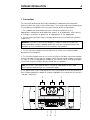
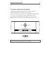
The connectors and controls are clearly marked on the back panel of the amplifier.
Note the correct left or right channel orientation. The function and channel markings on
the rear panel correspond to the front panel controls and their signal paths.
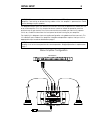
1. The unbalanced and balanced inputs should be attached to the
appropriate unbalanced and balanced outputs of a preamplfier either directly
or through a crossover or processor, as appropriate to the application.
2. The left output and right output should be attached to the left and right speakers
respectively.
WARNING: There are no fuses on the amplifier’s outputs in order to cut down on
output impedance effects. Speaker protection is left to the manufacturer of your
speakers, as they would best know how to protect their product.
3. The AC line input should be connected to an AC outlet with the power cable
provided with the amplifier.
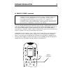
4. The fuse and voltage selector unit houses a 5x20mm slow-blow fuse and a voltage
selector cartridge. Ensure that the voltage, visible through a small window next to the
AC input, is set to the appropriate voltage for your country. When changing voltages,
ensure that the power cable is disconnected from the amplifier.
NOTE: If the fuse in your amplifier blows, contact a Coda dealer or call Coda
directly before attempting to use the amplifier again.
5. The power switch can usually be left on when the amplifier is functioning correctly.
With the bias disabled the amplifier will draw negligible current and can thus be left in
“standby” indefinitely.
2
1
INPUTS
2
INPUTS
UNBALANCED
UNBALANCED
BRIDGED
INPUT
BALANCED
PUSH
PUSH
BALANCED
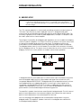
BRIDGED MODE
READ THE BRIDGING SECTION OF THE OPERATING MANUAL OR CONTACT YOUR CODA AUTHORIZED
DEALER TO SET THE BRIDGING SWITCHES
FOR CONTINUED PROTECTION AGAINST
SHOCK OR FIRE:
REPLACE FUSE WITH SAME TYPE AND
RATING. DO NOT EXPOSE THIS UNIT TO
RAIN OR MOISTURE
DO NOT CONNECT AMPLIFIER OUTPUT
TERMINALS
TOGETHER.
CONNECT
AMPLIFIER OUTPUT TERMINALS ONLY TO
SPEAKERS.
230
16 AMP
16 AMP
8 AMP
8 AMP
AC LINE INPUT
MAIN POWER
FUSE / VOLTAGE SELECTOR
SEE SERIAL TAG FOR POWER REQUIREMENTS.
REMOVE POWER CORD BEFORE CHANGING FUSE OR LINE VOLTAGE.
3
5
4