1
Table of Contents
Table of Contents
Product Overview......................................................... 4
Package Contents.................................................... 4
System Requirements.............................................. 4
Introduction............................................................... 5
Features.................................................................... 6
Hardware Overview.................................................. 8
Connections........................................................ 8
ICR and Built-in Microphone............................... 9
Compact Flash Card Slot.................................... 9
Hardware Installation.............................................. 10
Software Installation.................................................. 12
Configuration.............................................................. 15
Installation Wizard.................................................. 15
PPPoE Setup.................................................... 17
Web-based Configuration Utility............................. 23
Live Video......................................................... 24
Using RTSP Players......................................... 25
Using 3GPP Mobile Phones............................. 26
Camera............................................................. 27
Snapshot........................................................... 29
Client Setup...................................................... 30
Setup...................................................................... 31
Wizard............................................................... 31
Internet Connection Setup Wizard................ 31
Motion Detection Setup Wizard..................... 36
D-Link DCS-3110 User Manual
Network Setup.................................................. 39
Dynamic DNS................................................... 45
Image Setup..................................................... 46
Audio and Video................................................ 47
Motion Detection............................................... 49
Time and Date.................................................. 52
Event Setup...................................................... 53
Add Server.................................................... 55
Add Media..................................................... 56
Add Event...................................................... 59
Add Recording.............................................. 60
Advanced.......................................................... 61
DI and DO......................................................... 61
RS485........................................................... 62
ICR ............................................................... 64
Access List........................................................ 65
Maintenance........................................................... 66
Device Management......................................... 66
Backup and Restore......................................... 67
Firmware Update.............................................. 68
Status..................................................................... 69
Device Info........................................................ 69
Logs.................................................................. 70
Help........................................................................ 71
D-ViewCam Installation.............................................. 72
Add a Camera......................................................... 75
Table of Contents
Megapixel PoE Network Camera Features............... 80
Megapixel PoE Network Camera Installation........... 81
Networking Basics..................................................... 83
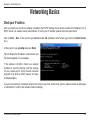
Check your IP address........................................... 83
Statically Assign an IP address.............................. 84
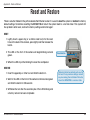
Reset and Restore...................................................... 85
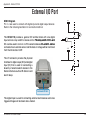
External I/O Port......................................................... 86
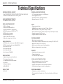
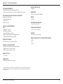
Technical Specifications............................................ 87
D-Link DCS-3110 User Manual
Section 1 - Product Overview
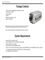
Product
PackageOverview
Contents
• D-Link DCS-3110 Megapixel PoE Network Camera
• CAT5 Ethernet Cable
• Power Adapter
• Screws
• Manual and Software on CD
• Quick Install Guide
Note: Using a power supply with a different voltage than the one included with
your product will cause damage and void the warranty for this product.
If any of the above items are missing, please contact your reseller.
System Requirements
•Windows® XP or Windows Vista®
•At least 256MB of memory (512MB recommended)
•Internet Explorer 6.x or higher
•VGA card resolution: 800 x 600 or above
•CPU: 1.7GHz or above (2.8GHz plus processor with 512MB memory and a 32MB video card is required
for multiple camera viewing and recording in IP surveillance program)
•An available Ethernet connection
D-Link DCS-3110 User Manual
Section 1 - Product Overview
Introduction
DCS-3110 is an ideal network camera for professional surveillance and security applications. This camera adopts a
1.3 mega-pixel progressive scan CMOS sensor and the motion JPEG stream covers three times larger scene which
is also at least three times higher than analog CCTV cameras. This is also a very important consideration in video
surveillance applications, where a high resolution image helps to identify a criminal.
Two video streams with different configurations can be activated simultaneously to address different requirements
for live viewing and recording. Multicast video/audio stream helps to reduce the network transmission load. When a
multicast-enabled router is used, the network camera can serve multiple clients at the same time.
The DCS-3110 has a built-in �������������������������������������������������������������������������������������������
removable IR-cut filter and is
���������������������������������������������������������������
designed for both indoor/outdoor (with enclosure) day/night
applications. The camera is equipped with one digital input and one digital output. An RS-485 port is designed for
external pan/tilt/zoom devices. An 802.3af compliant power over Ethernet (PoE) module is built-in to ease the installation
process.
With the free-bundled 32-channel recording software (D-ViewCam), this network camera provides a total solution for
high quality live viewing and reliable recording.
D-Link DCS-3110 User Manual
Section 1 - Product Overview
Features
• Powerful Surveillance - The DCS-3110 is designed to target the high-end surveillance market. As mentioned
earlier, a 1.3 mega-pixel progressive scan CMOS sensor covers three times larger view. The DCS-3110
is a powerful network camera for both day and night applications. It effectively reduces motion blur and
distortion as well as jagged edges of recorded images. With a removable IR-cut filter, the Network Camera
always provides high-quality images in both daytime and nighttime. An RS-485 port is designed for external
pan/tilt/zoom devices. It supports DC12V output for external devices like IR light.
• Sharp Image Monitoring - DCS-3110 provides high quality real-time videos in MPEG-4 and JPEG
compression with VGA/QVGA/QQVGA resolution. It is also suitable for narrow space surveillance, like an
elevator.
• View Live Video from a 3G Mobile Phone - The live video feed of the Network Camera can be pulled from
the 3G cellular network by using a compatible cell phone or PDA with a 3G video player. Users are offered
a flexible and convenient way to remotely monitor a home or office in real time, �������������������������
anywhere within the 3GPP
service area.
• Wired PoE Access - For effective surveillance in or around a building, this camera comes with a built-in
802.3af compliant Power Over Ethernet (PoE) module, which eases the installation process and also gives
you the freedom to place the camera where it’s needed. In addition, the 10/100BASE-TX Ethernet port
provides convenient connection to an Ethernet network or to broadband Internet via a router.
• Smart & Easy To Use - The software allows you to view up to 32 cameras on a single computer screen at
one central location. Users can set up automated e-mail alerts to be instantly informed of unusual activities.
In addition, this network camera supports the universal plug-n-play (UPnP™) feature, which allows computers
running on Windows® XP/Vista to automatically recognize the camera and adds it to the network. Sign up
with one of the free Dynamic DNS services available on the web to assign a domain name to the camera
(e.g.mycamera.dlinkddns.com). This allows users to remotely access the camera without having to remember
the IP address.
D-Link DCS-3110 User Manual
Section 1 - Product Overview
• Supported Protocols - DCS-3110 supports a wide variety of protocols such as RTSP, FTP, SMTP, NTP
and HTTP. In addition, the camera supports UPnP and DDNS.
• Web Configuration - Using a Web browser, administrators can configure and manage the network camera
directly from its own web page via your network or the Internet. Up to 20 user accounts can be created with
privilege settings controlled by the administrator.
• Connection to External Devices - Supporting auxiliary Input/Output connectors, you can connect the
Network Camera to a variety of external devices such as IR-sensors, switches and alarm relays. Combined
with programmable alarm equipment, you can develop a variety of security applications that are triggered
on alarm-based events. The Network Camera provides an industry standard in/out external connector for
connectivity.
• MPEG4 Multicast Stream Support – Unicast video is delivered through point-to-point transmission. On
the other hand, with a multicast stream, the server streams to a multicast IP address on the network, and
clients receive the stream by subscribing to the IP address. Because there is only one stream from the server
regardless of the number of clients receiving the stream, a multicast stream requires the same amount of
bandwidth as a single unicast stream containing the same content. Using a multicast stream preserves
network bandwidth.
• Samba Client Support – ���������������������������������������������������������������������������
DCS-3110 has ��������������������������������������������������������������
a built-in Samba client for NAS, and hence does not require a
direct connection to a PC or any other hardware or software to capture and transfer images.
Note: Use of audio or video equipment for recording the image or voice of a person without their knowledge and consent is prohibited in
certain states or jurisdictions. Nothing herein represents a warranty or representation that the D-Link product provided herein is suitable
for the end-user’s intended use under the applicable laws of his or her state. D-Link disclaims any liability whatsoever for any end-user use
of the D-Link product, which fails to comply with applicable state, local, or federal laws.
D-Link DCS-3110 User Manual
Section 1 - Product Overview
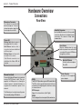
Hardware Overview
Connections
Microphone Connector:
The camera has an internal
built-in microphone. To use an
external microphone, plug it into
the microphone connector.
Status LED
Blinking Red: indicates power is
being supplied to the camera.
Solid Green: indicates that a
connection has been established
via Ethernet port.
Blinking Green: indicates traffic
movement in the camera.
If the Ethernet connection is not
established the Status LED will
not glow.
Ethernet Port (PoE)
Connect the Network Camera to your network
using a CAT5 Ethernet cable. This port
supports the NWay protocol, allowing the
network camera to automatically detect or
negotiate the transmission speed of the
network.
The Ethernet port can also be used to power
the camera by using a PoE switch.
D-Link DCS-3110 User Manual
Rear View
Audio Out Connector:
Use the Audio Out connector for 2-way audio
connection. Speakers (not included) may be
connected to the camera for 2-way audio
communication.
Reset Button
Reset is initiated when the reset
button is pressed once and held 30
seconds until the power LED flashes
through its cycle twice.
Mic On/Off Switch:
Select to turn the microphone
On or Off.
DI/DO:
The DCS-3110 provides a general I/O terminal block.
The I/O connectors provide the physical interface to
send and receive digital signals to and from a variety
of external devices.
DC12V output :
Support for external device (like IR light)
RS485:
Port is designed for external pan/tilt/zoom devices.
Power Receptor
Receptor for the supplied
power adapter.
Section 1 - Product Overview
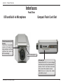
Interfaces
Front View
ICR and Built-in Microphone
IR-Cut Removable (ICR)
Sensor
The IR-Cut removable
sensor will judge the
light conditions and then
switches from color to
B/W accordingly.
Compact Flash Card Slot
Built-in Microphone
CF card slot
CompactFlash (CF) is a mass storage
device format used in portable electronic
devices. The CF card slot can be seen
at the side of the network camera.
Note: Ensure to remove the rubber
strip before using it.
D-Link DCS-3110 User Manual
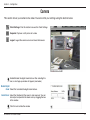
Section 2 - Hardware Installation
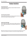
Hardware Installation
Connect the Ethernet Cable
Connect an Ethernet cable to the Ethernet port located on the Network Camera’s back
panel and attach it to the network.
Connect Using Power-Over-Ethernet
Once you connect an Ethernet cable to your PoE switch or adapter, the Power LED on
the DCS-3110 will turn green to indicate a proper connection.
Attach the External Power Supply
Attach the supplied power adapter to the DC power input connector located on the
Network Camera’s back panel (labeled DC 12V) and connect the other end to an AC
power outlet.
Note: The LED on the network camera will turn green, when you have a proper connection. The light might go on and off and your
computer may show an intermittent loss of connectivity, this is normal until you have configured your Network Camera.
D-Link DCS-3110 User Manual
10
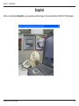
Section 2 - Hardware Installation
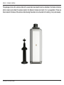
The package comes with a camera stand with a swivel ball screw head that can be attached to the Network Camera
bottom socket cavity. Attach the camera stand to the Network Camera and station it for your application. There are
holes located in the base of the camera stand allowing the camera to be mounted to the ceiling, or any wall securely.
D-Link DCS-3110 User Manual
11
Section 3- Software Installation
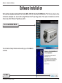
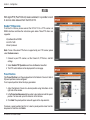
Software Installation
Turn on the computer and insert the D-Link DCS-3110 CD into the CD-ROM drive. The following step-by-step
instructions displayed are shown when using Windows Vista® operating system. The steps and screens are similar
when using other Windows® operating systems.
Click on Installation Wizard
The Installation Setup Wizard window will pop up. Click Next to
continue.
Click Next
D-Link DCS-3110 User Manual
12
Section 3- Software Installation
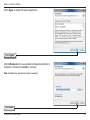
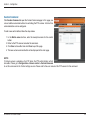
Click I Agree to accept the License Agreement.
Click I Agree
Click the Browse button if you would like to change the destination of
installation, otherwise click Install to continue.
Note: Installation may take several minutes to complete.
Click Install
D-Link DCS-3110 User Manual
13
Section 3- Software Installation
Click Finish to complete installation and the D-Link Installation
Wizard window will pop up for camera configuration.
Click Finish
D-Link DCS-3110 User Manual
14
Section 4 - Configuration
Configuration
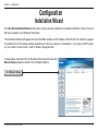
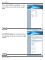
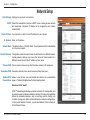
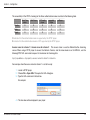
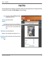
Installation Wizard
If the D-Link Installation Wizard window does not pop up after completion of software installation, click on the icon
that was created in your Windows Start Menu.
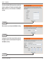
The Installation Wizard will appear and show the MAC address and IP address of the DCS-3110, which may appear
to be different from the actual address depending on what your device is connected to. If you have a DHCP server
on your network, there will be a valid IP address displayed here.
To begin setup, select the DCS-3110 located in the camera list and click
Manual Setup located on the left of the Installation Wizard.
Click Manual Setup
D-Link DCS-3110 User Manual
15
Section 4 - Configuration
Enter a password, and confirm the password for the admin ID
and click Next.
Note: The default administrator username is set to admin and the password
may be left blank. The password can be changed after installation.
Click Next
D-Link DCS-3110 User Manual
16
Section 4 - Configuration
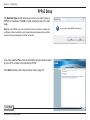
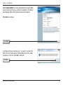
PPPoE Setup
The Network Type prompt will pop up to ask if you want to setup a
PPPoE for the device. Click No for quick setup and skip to the next
page.
Note: By using PPPoE, users can virtually dial from one machine to another over
an Ethernet network, establish a point to point connection between them and then
securely transport data packets over the connection.
If you have selected Yes, enter the username and password provided
by your ISP to connect to the Internet by PPPoE.
Click Next and skip to the setup screen as seen in page 19.
Click Next
D-Link DCS-3110 User Manual
17
Section 4 - Configuration
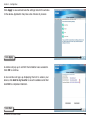
Check the Get IP by DHCP Server automatically box to obtain
a new IP address every time the camera starts up. Click Next to
continue.
Click Next
Select UPnP Port Forwarding if your router supports this function. If
not, choose Manual to manually enter your port numbers. Click Next
to continue.
Click Next
D-Link DCS-3110 User Manual
18
Section 4 - Configuration
Select Enable DDNS if you have subscribed to a Dynamic DNS
account and would like your camera to update its IP address
automatically. Enter all the relevant account information.
Click Next to continue.
Click Next
A window will pop up asking you if you want to access the
DCS-3110 via mobile phone. Clicking Yes will set the video
resolution to 176x144. Click No to continue.
Click No
D-Link DCS-3110 User Manual
19
Section 4 - Configuration
Click Apply to save and activate the settings listed in the window
to the device. Application may take a few minutes to process.
Click Apply
A window will pop up to confirm the installation was successful.
Click OK to continue.
A new window will pop up displaying the lists to access your
device, click Add to my favorite to save the address and then
click Exit to complete installation.
Click Exit
D-Link DCS-3110 User Manual
20
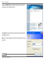
Section 4 - Configuration
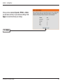
Double-click DCS-3110 in the Installation Wizard window to launch
the camera’s web configuration utility.
Enter admin as the default username and leave the password blank.
Click OK to continue.
Note: If you have changed your password, please enter your new
password.
Click OK
D-Link DCS-3110 User Manual
21
Section 4 - Configuration
This section shows your camera’s live video. You can control your settings using the buttons below.
D-Link DCS-3110 User Manual
22
Section 4 - Configuration
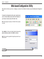
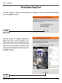
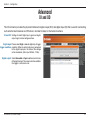
Web-based Configuration Utility
This section will show you how to configure your new D-Link Network Camera using the Web-based Configuration
Utility.
To access the configuration utility, open a web-browser
such as Internet Explorer and enter the IP address of
your Network Camera (http://192.168.0.120)
Note: In the example, this address is 192.168.0.120. Your address
may differ.
Type Admin in the user name field and leave the
password blank by default. Click OK to continue.
Note: You may refer to page 66 to change the password for your
admin account.
Click OK
D-Link DCS-3110 User Manual
23
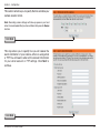
Section 4 - Configuration
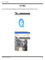
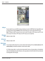
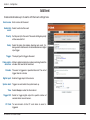
Live Video
As seen by Mozilla Firefox and Netscape users, Quick Time player is invoked to stream the live video.
D-Link DCS-3110 User Manual
24
Section 4 - Configuration
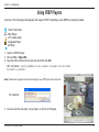
Using RTSP Players
Use one of the following media players that support RTSP streaming to view MPEG-4 streaming media.
Quick Time Player
Real Player
VLC media player
mpegable Player
pvPlayer
1. Launch a RTSP player.
2. Choose File > Open URL.
3. Type the URL command in the text box and then click OK.
URL command = rtsp://<ip address of your camera>:<rtsp port>/<access name
for stream1 or stream2>
Note: Please refer to pages 39-44 for the settings of your RTSP port and stream files.
For example:
4. You can view the live video in your player, as shown in the figure.
D-Link DCS-3110 User Manual
25
Section 4 - Configuration
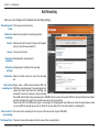
Using 3GPP Mobile Phones
To view streaming media using mobile phones, make sure the Network Camera is setup on the Internet.
To utilize this feature, please check the Network Settings for your camera.
1. Most of the players on 3GPP mobile phones do not support RTSP authentication, make sure the
authentication mode of RTSP streaming is set to Disable. For more information, see RTSP Streaming
on page 42.
2. The 3G network bandwidth is limited, therefore users cannot use large size videos. Please set the
video and audio streaming parameters as listed below. For more information, see Audio and Video
on page 47.
Video Mode
MPEG-4
Frame size
176 x 144
Maximum frame rate
5 fps
Intra frame period
1S
Video quality (Constant bit rate)
40kbps
Audio type (GSM-AMR)
12.2kbps
3. Set the RTSP port to 554, since most ISPs and players do not support other port numbers.
4. Launch the players on 3GPP mobile phones, (ex. Real Player). Type the URL command in the player.
URL Command = rtsp://<public ip address of your camera>:<rtsp port>/<access name for stream1/
stream2>
D-Link DCS-3110 User Manual
26
Section 4 - Configuration
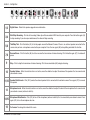
Camera
This section shows your camera’s live video. You can control your settings using the buttons below.
Client Settings: Click this button to access the Client Settings.
Snapshot: Captures a still picture of a video.
Logout: Logout the camera server and close the browser.
Enable/Disable the digital zoom feature. After selecting this
icon, a small pop-up window will appear (see below).
Disable Digital
Zoom: Select this to disable the digital zoom feature.
Zoom Factors: Adjust the threshold of the zoom in and zoom out. You can
also adjust and position the zoom area by dragging the box
in the window.
Click this icon to hide the window.
D-Link DCS-3110 User Manual
27
Section 4 - Configuration
1
2
3
4
5
6
7
8
9
10
11 12
13 14
15
16
1/2
Digital Zoom - Refer to the previous page for more information.
3/4
Start/Stop Recording - Click to start recording. Video clips will be recorded in MP4 format to your computer. Press the button again (#4)
to stop recording. If you close your web browser, the video will stop recording.
5/6
Talk/Stop Talk - Click this button (#5) to talk to people around the Network Camera if there is an external speaker connected to the
camera and you have a microphone connected to your computer. Press the icon again (#6) to stop talking or disable this function.
7/8
Resume/Pause - Click this button (#8) to start or resume the transmission of video streaming. Click the button again (#7), the video will
pause.
9
Stop - Click to stop the transmission of video streaming. Click the resume button (#8) to begin streaming.
10
Speaker Volume - When the mute function is not active, move the slider bar to adjust the volume of the speakers that are connected to
your network camera.
11/12
Speaker Mute/Unmute - Click (#12) to mute the external speaker that is connected to the network camera. Press again (#11) to unmute
the speaker.
13
Microphone Level - When the mute function is not active, move the slider bar to adjust the level of the microphone that is connected to
your network camera (external or built-in).
14/15
Microphone Mute/Unmute - Click (#15) to turn off the microphone (external or built-in) that is connected to your network camera. Press
again (#14) to turn the microphone back on.
16
Full screen: To enlarge the video to full screen.
D-Link DCS-3110 User Manual
28
Section 4 - Configuration
Snapshot
After you have clicked Snapshot a pop-up window with an image of live video taken by the DCS-3110 will appear.
D-Link DCS-3110 User Manual
29
Section 4 - Configuration
Client Setup
To configure the settings for media streaming and recording, please read the following definitions.
Stream Options: Select which video stream profile to use.
Protocol There are 4 protocols for you to choose for video
Options: streaming.
UDP Protocol: This is recommended because it is an ideal protocol
for transmitting real-time audio and video data, which
can tolerate some lost packets.
UDP Unicast: Stream to a single computer.
UDP Multicast Stream to multiple computers using multicast
streaming.
TCP: Provides higher quality video streaming than UDP
and provides error correction. However, transmission
speed will be reduced.
HTTP Protocol: Offers the highest image and video quality. However,
packet loss will diminish image quality when
bandwidth becomes restricted. If the network is
protected by a firewall and it opens HTTP port (80)
only, HTTP protocol must be selected. In this mode,
audio is disabled and only video can be viewed. UDP
connections will not be available to remote users if all four ports have not been forwarded (as shown on page 43). Only the
HTTP port must be forwarded for remote users to make an HTTP connection (video only).
Record Options: Allows the user to specify a destination folder and prefix filename for the recorded video.
D-Link DCS-3110 User Manual
30
Section 4 - Configuration
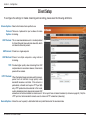
Setup
Wizard
To quickly configure your network camera, click Internet
Connection Setup Wizard or click Manual Internet
Connection Setup to manually configure your network
camera.
To quickly configure your network camera’s motion
detection settings, click Motion Detection Setup
Wizard and skip to page 36. If you want to enter your
settings without running the wizard, click Manual
Motion Detection Setup and skip to page 49.
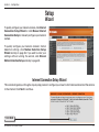
Internet Connection Setup Wizard
This wizard will guide you through a step-by-step process to configure your new D-Link Camera and connect the camera
to the internet. Click Next to continue.
Click Next
D-Link DCS-3110 User Manual
31
Section 4 - Configuration
Select DHCP if you are unsure which settings to pick.
Click Next to continue and skip to page 34.
Click Next
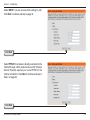
Select PPPoE if the camera is directly connected to the
Internet through a DSL modem and your ISP (Internet
Service Provider) requires you to use PPPoE for the
Internet connection. Click Next to continue and skip to
Step 2 on page 33.
Click Next
D-Link DCS-3110 User Manual
32
Section 4 - Configuration
Select Static IP if your Internet Service Provider has
provided you with connection settings, or you wish to set
a static address within your home network. Click Next
to continue.
Click Next
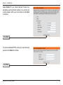
If you have selected PPPoE, enter your username and
password. Click Next to continue.
Click Next
D-Link DCS-3110 User Manual
33
Section 4 - Configuration
If you have a Dynamic DNS account and would like the
camera to update your IP address automatically, enable
DDNS and enter your host information. Click Next to
continue.
Click Next
Enter a name for your camera and click Next to continue.
Click Next
Configure the correct time to ensure that all events will
be triggered, captured, and scheduled at the right time.
Click Next to continue.
Click Next
D-Link DCS-3110 User Manual
34
Section 4 - Configuration
Once you have selected Dynamic, PPPoE, or Static,
you will see a summary of your camera’s settings. Click
Apply to save and activate your settings.
Click Apply
D-Link DCS-3110 User Manual
35
Section 4 - Configuration
Motion Detection Setup Wizard
This wizard will guide you through a step-by-step process to configure your new D-Link Camera’s motion detection
functions. Click Next to continue.
Click Next
This section will allow you to enable or disable motion
detection as well as control the sensitivity of your
camera’s ability to detect movement. Specify the window
area, window name, and sensitivity of detection as well
as the type of recording (either snapshot of video clip).
Click Next to continue.
Click Next
D-Link DCS-3110 User Manual
36
Section 4 - Configuration
This section will allow you to specify the time and date your
camera records motion.
Note: Recording camera footage will take up space on your hard
drive. Its recommended that you have sufficient disk space for Always
function.
Click Next
This step allows you to specify how you will receive the
events notification of your camera, either via using email
or FTP. You will need to enter all the relevant information
for your email account or FTP settings. Click Next to
continue.
Click Next
D-Link DCS-3110 User Manual
37
Section 4 - Configuration
You have completed the Motion Detection Wizard. Click
Apply to save your settings.
Click Apply
D-Link DCS-3110 User Manual
38
Section 4 - Configuration
Network Setup
LAN Settings: Settings for your local area network.
DHCP: Select this connection if you have a DHCP server running on your network
and would like a dynamic IP address to be assigned to your camera
automatically.
Static IP Client: You may enter a static or fixed IP address for your camera.
IP Address: Enter an IP address.
Subnet Mask: The default value is “255.255.255.0.” Used to determine if the destination
is in the same subnet.
Default Gateway: The gateway used to forward frames to destinations in a different subnet.
Invalid gateway settings may cause the failure of transmissions to a
different subnet. Usually the IP address of your router.
Primary DNS: Primary domain name server that translates names to IP addresses.
Secondary DNS: Secondary domain name server to backup the primary one.
Enable UPnP Allows a user to find, view, and control this camera via a presentation
Presentation: page or “Network Neighborhood” without configuration.
How does UPnP work?
UPnPTM networking technology provides automatic IP configuration and
dynamic discovery of devices added to a network. Services and capabilities
offered by networked devices, such as printing and file sharing, are
available among each other without bothersome network configuration.
In the case of Network Cameras, you will see Network Camera shortcuts
at My Network Places.
D-Link DCS-3110 User Manual
39
Section 4 - Configuration
Enabling UPnP port forwarding allows the Network Camera to open a secondary HTTP port on the router. You have
to add the secondary HTTP port number behind the Network Camera’s public address in order to access the Network
Camera from the Internet. For example, when the HTTP port is set to 80 and the secondary HTTP port is set to 8080,
refer to the list below for the Network Camera’s IP address.
From the Internet
In a local area network
http://203.67.124.123:8080
http://192.168.4.160 or
http://192.168.4.160:8080
If the PPPoE settings are incorrectly configured or the Internet access is not working, restore the Network Camera to
factory default settings.
Enable UPnP Port Enables the camera to add the port forwarding entry into the router automatically when this option is enabled.
Forwarding:
PPPoE Settings: Enable this setting if your ISP (DSL service) is using PPPoE. You may already have both Username and Password given
by your ISP, or you may check with your ISP. The Connect Status will be determined automatically by the system.
HTTP: You may configure two HTTP ports for your camera. HTTP ports allow you to connect to the camera via a standard web
browser. These ports can be set to a number other than the default TCP ports 80 and 8080. A corresponding port must be
opened on the router. For example, if the port is changed to 1010, users must type in the web browser “http://192.168.0.1
00:1010” instead of “http://192.168.0.100”.
Authentication: Authentication: Choose either Basic where the password is not encrypted, or Digest where the password is encrypted
during the transmission to the web server.
Note: Ensure to restart your browser, if you select Digest mode.
Basic authentication: When selected, the password is sent in plain text format; there can be potential risks of being
intercepted.
Digest authentication: When selected, user credentials are encrypted in MD5 algorithm and thus provide better protection
against unauthorized accesses.
HTTP Port: The default value is 80.
D-Link DCS-3110 User Manual
40
Section 4 - Configuration
Secondary HTTP The default value is 8080.
Port: After you have enabled the Authentication, you will need to configure and use the access name to access your video file.
For example, http://camera ip/video.mjpg (video.mjpg is the Access name, you can modify it here)
Access name for The default name is video.mjpg.
stream1:
Access name for The default name is video2.mjpg.
stream2:
Access name for stream 1 / Access name for stream 2 : The access name is used to differentiate the streaming
source. When using Mozilla Firefox or Netscape to access the Network Camera, and the video mode is set to JPEG,
users will receive continuous JPEG pictures. This technology, known as "server push", allows the Network Camera to
feed live pictures to Mozilla Firefox and Netscape. Use the following command to obtain the JPEG file:
http://<ip address>:<http port>/<access name for stream1 or stream2>
For example, when the access name for stream 1 is set to video.mjpg:
1. Launch Mozilla Firefox or Netscape
2. Type the URL command in the address field. Press Enter.
3. The JPEG image will be displayed in your web browser.
FTP Port: Default port is 21. If you want to change the port number, you will need to specify the port when connecting to the FTP
server. For example, FTP://68.5.1.81:60 (if you use port 60 for your FTP server)
RTSP Streaming: This setting enables you to connect to a camera by using streaming mobile device(s), such as a mobile phone or PDA.
Authentication: Select either Basic where the password is not encrypted, or Digest where the password is encrypted during the transmission
to the web server. After you have enabled the Authentication, you will need to configure and use the access name to
access your video file. RTSP://camera ip/live.sdp (live.sdp is the default access name, you can modify it here)
Access name for The default name is live.sdp.
stream1:
Access name for The default name is live2.sdp.
stream2:
D-Link DCS-3110 User Manual
41
Section 4 - Configuration
The accessibility of the RTSP streaming for the three authentication modes are listed in the following table.
Quick Time
player
Real Player
VLC media
player
mpegable
Player
pvPlayer
Disable
O
O
O
O
O
Basic
O
O
X
X
X
Digest
O
X
X
X
X
O indicates that the authentication mode is supported by the RTSP player.
X indicates that the authentication mode is NOT supported by the RTSP player.
Access name for stream 1 / Access name for stream 2 : The access name is used to differentiate the streaming
source. When using a RTSP player to access the Network Camera, and the video mode is set to MPEG-4, use the
following RTSP URL command to request a transmission of streaming data.
rtsp://<ip address>:<rtsp port>/<access name for stream1 or stream2>
For example, when the access name for stream 1 is set to live.sdp:
1 : Launch a RTSP player.
2 : Choose File > Open URL. This opens the URL dialog box.
3 : Type the URL command in the text box.
For example:
4 : The live video will be displayed in your player.
D-Link DCS-3110 User Manual
42
Section 4 - Configuration
RTSP port:
The port number that you use for RSTP streaming, the default port number is 554. RTP (Real Time Protocol) Port is used
to streaming audio and video while RTCP (Real Time Control Protocol) port is used to monitor QoS of RTP stream.
Note: RTP video port and RTP audio port must be an “even” number. The numbers of RTCP video port and RTCP audio
port must equal to the numbers of RTP video port and RTP audio port, plus one repetitively.
RTP port for
video: Default port number is 5556.
RTCP port for
video: Default port number is 5557.
Multicast group
address: You may choose to enable multicast for your camera audio and video streaming so that your cameras (sources) and the
receivers (clients) can establish the connection to send and receive contents.
An IP Multicast group address is used to send and receive content. Sources use this group address as the destination
address while sending their data packets. Receivers use this group address to inform the network that they are interested
in receiving packets sent to that group.
D-Link DCS-3110 User Manual
43
Section 4 - Configuration
For example, if some content is associated with group 239.1.1.1, the source will send data packets destined to 239.1.1.1.
Receivers for that content will inform the network that they are interested in receiving data packets sent to the group
239.1.1.1. The receiver “joins” 239.1.1.1. The Multicast address ranges from 224.0.0.0 to 239.255.255.255, or, equivalently,
224.0.0.0/4
Multicast video
port: Default port number is 5560, or please choose between 1024 and 65534.
Multicast RTCP
video port: Default port number is 5561, or please choose between 1024 and 65534.
Multicast RTCP
audio port: Default port number is 5563, or please choose between 1024 and 65534.
Multicast TTL
{1~255]: Set a Time to Live(TTL) value for multicast packet, please choose between 1 and 255.
Two way
audio port: The two way audio port in DSC-3415 is set to 5060, by default. It can also be assigned to another port number between 1025
and 65535. This Network Camera supports two way audio communication so that operators can transmit and receive audio
simultaneously. By using the camera’s built-in microphone and an external speaker, users can communicate with people
present around the Network Camera.
Note: Since JPEG only transmits a series of JPEG images to the client, to utilize this feature, make sure the video mode is
set to MPEG-4 and the media option is set to Video and Audio.
Unicast video transmission delivers a stream through point-to-point transmission. On the other hand, multicast video
transmission sends a stream to the multicast group address and allows multiple clients to acquire the stream by
requesting a copy from the Multicast group address.
The five ports can be changed between 1025 and 65535. The multicast RTP port must be an even number and the
multicast RTCP port is multicast RTP port number plus one, and thus always be odd. When the multicast RTP port
changes, the multicast RTCP port will change accordingly.
D-Link DCS-3110 User Manual
44
Section 4 - Configuration
Dynamic DNS
DDNS (Dynamic Domain Name Server) will hold a DNS host name and synchronize the public IP address of the modem
when it has been modified. The username and password are required when using the DDNS service.
Enable DDNS: Click to enable the DDNS function.
Server Name: Select your Dynamic DNS provider from the drop
down menu.
Host Name: Enter the host name of the DDNS server.
Username: Enter your username or e-mail used to connect
to the DDNS
Password: Enter your password used to connect to the DDNS
server.
Status: Displays the current connection status.
D-Link DCS-3110 User Manual
45
Section 4 - Configuration
Image Setup
You may configure the color, brightness, and orientation settings of the video image. Preview of the image will be shown
in the window of Live Video. Click Save Settings to save your changes.
Color: Select either for Color or B/W (black and white,
monochrome) video display.
Power line Select either 50 or 60Hz.
frequency:
Video Flip will vertically rotate the video while Mirror will
orientation: horizontally rotate the video. You may check both
options if the camera is being installed upside
down.
White balance: Choose either Auto or Fix.
Brightness: Select the brightness level ranged from -5 to +5.
Overlay title and Select to add a date and time stamp on the video.
time stamp on
video:
D-Link DCS-3110 User Manual
46
Section 4 - Configuration
Audio and Video
Settings for two video streams (stream 1 and stream 2) can be configured here. You may configure one setting for
computer display and the other one for mobile display.
Mode: Select either JPEG or MPEG4. In JPEG mode, the
video frames are independent. However, MPEG4
consumes much less network bandwidth than
JPEG.
Frame Size: Select 176x144, 352x240, or 640x480. It is
recommended using 176x144 for mobile viewing
and 640x480 for computer viewing.
Maximum 1 is the minimum value while 30 is the maximum
frame rate: value. It is recommended choosing 30 for computer
viewing and 5 for mobile viewing.
Video quality: This limits the maximum refresh frame rate, which
can be combined with the “Fixed quality” to optimize
the bandwidth utilization and video quality. If the User
wants to fix the bandwidth utilization regardless of the
video quality, choose “Constant bit rate” and select
the desired bandwidth.
Mute: Select this to mute audio.
Internal Select an internal microphone input gain from the
microphone drop-down list.
input gain: It is necessary to find the optimum gain that transmits the best audio for listening.
Note: “dB” stands for decibels, a logarithmic unit of measurement in acoustics . The higher the decibel number, the louder
the sound.
D-Link DCS-3110 User Manual
47
Section 4 - Configuration
External Select the external microphone input gain from the list.
microphone
input:
Audio type: AAC (Advanced Audio Coding): A wide band audio coding algorithm that exploits two primary coding strategies to dramatically
reduce the amount of data needed to convey high-quality digital audio. Select a higher bit rate number for better audio
quality.
GSM-AMR: A standard adapted audio codec by the 3GPP video (3rd Generation Partnership Project). It is an Adaptive Multi Rate-Narrow
Band (AMRNB) speech codec. Select a higher bit rate number for better audio quality.
AAC bit rate: Select an AAC bit rate from the list. Higher bit rate means higher audio quality but it takes more network bandwidth to
transmit.
GSM-AMR Select the GSM-AMR bit rate from the list. Higher bit rate means higher audio quality but it takes more network bandwidth
bit rate: to transmit.
D-Link DCS-3110 User Manual
48
Section 4 - Configuration
Motion Detection
Enabling Motion Detection will allow up to three windows that can be created with different settings for monitoring. This
allows your camera to serve as a security device that will record when motion is detected.
Enable motion Check this option to turn on the motion detection
detection: feature.
Window name: Create your own name for the monitored area/
window. It will show at the top of the motion
window.
Sensitivity: Set the measurable difference between two
sequential images that would indicate motion.
Percentage: Set the amount of motion in the window being
monitored that is required to initiate a motion
detected alert. If this is set to 100%, this means
that motion must be detected within the whole
window to trigger a snapshot.
Note: Setting a higher sensitivity and a lower
percentage will make motion easier to be
detected.
New: Click to add a new window. A maximum of three
motion windows can be opened simultaneously.
Use your mouse to drag the window frame to
re-size or the title bar to move. Clicking on the ‘x’
at the upper right corner of the window will close
the window.
Save: Save the related settings of that window.
D-Link DCS-3110 User Manual
49
Section 4 - Configuration
To enable motion detection, follow the steps below:
1. Click New to add a new motion detection window.
2. Enter a name in the Window Name field.
3. Define the sensitivity to moving objects and the space ratio of all alerted pixels by moving the Sensitivity and
Percentage slide bar.
4. Click Save to apply the changes.
5. Select Enable motion detection to activate motion detection.
Note: Drag to resize the window and click X to close the window.
The Percentage Indicator will rise or fall depending on the image variation. When motions are detected by the Network
Camera and are judged to exceed the defined threshold, a red bar rises. Meanwhile, the motion detection window will
be outlined in red. Utilizing this device as a trigger source, photos or videos can be captured instantly and sent to the
remote server (Email, FTP).
A green bar indicates that even though motions are detected, the event will not be triggered because the image variations
are still falling under the defined threshold.
Percentage = 30%
D-Link DCS-3110 User Manual
50
Section 4 - Configuration
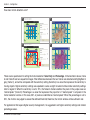
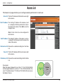
How does motion detection work?
A
C
B
D
There are two parameters for setting the motion detection: Sensitivity and Percentage. In the illustration above, frame
A and frame B are two sequential images. Pixel differences between the two frames are detected and highlighted in
gray (frame C), and will be compared with the sensitivity setting. Sensitivity is a value that expresses the sensitivity to
moving objects. Higher sensitivity settings are expected to sense a slight movement while smaller sensitivity settings
tend to neglect it. When the sensitivity is set to 70%, the Network Camera defines the pixels in the purple areas as
“alerted pixels” (frame D). Percentage is a value that expresses the proportion of “alerted pixels” to all pixels in the
motion detection window. In this case, 50% of pixels are identified as “alerted pixels”. When the percentage is set to
30%, the motions are judged to exceed the defined threshold; therefore, the motion window will be outlined in red.
For applications that require higher security management, it is suggested to set higher sensitivity settings and smaller
percentage values.
D-Link DCS-3110 User Manual
51
Section 4 - Configuration
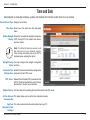
Time and Date
Automatically or manually configure, update, and maintain the internal system clock for your camera.
Current Server Time: Displays current time.
Time Zone: Select your time zone from the drop-down
menu.
Enable Daylight Select this to enable the daylight saving time
Saving: (DST). During DST, the system clock moves
one hour ahead.
Note: To utilize this feature, ensure to set
the time zone of your network camera.
Then starting and ending time of the DST is
displayed upon selecting the option.
Daylight Saving You may configure the daylight saving date
Dates: and time.
Automatic Time Enable this feature to obtain time configuration
Configuration: automatically from NTP server.
NTP Server: Network Time Protocol (NTP) synchronizes the
DCS-3110 with an Internet time server. Choose
the one that is closest to your location.
Update Interval: The time interval for updating the time information from NTP server.
Set the date and This option allows you to set the time and date manually.
time manually:
Copy Your This will synchronize the time information from your PC.
Computer’s Time
Settings:
D-Link DCS-3110 User Manual
52
Section 4 - Configuration
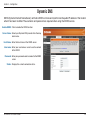
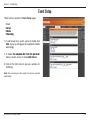
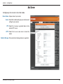
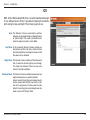
Event Setup
There are four sections in Event Setup page.
• Event
• Server
�������
• Media
�����
• Recording
���������
1. To add a new item - event, server or media click
Add. A pop-up will appear and update the fields
accordingly.
2. To delete �������������������������������������
the selected item from the pull-down
menu of event, server or media click
������ Delete.
3. Click on the item name to pop up a window for
modifying.
Note: You can add up to four events, five servers and five
media fields.
D-Link DCS-3110 User Manual
53
Section 4 - Configuration
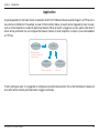
Application
A typical application is that when motion is detected, the DCS-3110 Network Camera sends images to a FTP server or
via e-mail as notifications. For example, as seen in the illustration below, an event can be triggered by many sources,
such as motion detection or external digital input devices. When an event is triggered, you can specify what kind of
action will be performed. You can configure the Network Camera to send snapshots or videos to your email address
or FTP site.
Action
Event Condition
ex.
Motion detection,
Periodically, Digital input,
System reboot
Media
(what to send)
ex.
Snapshot, Video Clips
Server
(where to send)
ex.
Email, FTP
To start plotting an event, it is suggested to configure server and media columns first so that the Network Camera will
know what action shall be performed when a trigger is activated.
D-Link DCS-3110 User Manual
54
Section 4 - Configuration
Add Server
Configure up to 5 servers to store the media.
Server Name: Unique name of your server.
Email: Select this to enable and apply your email account
setting for your camera.
FTP: Select this to access a granted folder on the
external FTP server.
HTTP: Select this to use a web server to store the
media.
Network Storage: Only one network storage device is supported.
D-Link DCS-3110 User Manual
55
Section 4 - Configuration
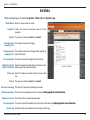
Add Media
There are three types of media, Snapshot, Video Clip and System Log.
Media Name: Enter an unique name for media.
Snapshot: Select this feature to enable camera to take
snapshot.
Source: The source of stream: stream1 or stream2.
Send pre-event The number of pre-event images.
image(s) [0~7]:
Send post-event The number of post-event images. Refer page 57 for
image(s) [0~7]: more information.
File name prefix: The prefix name will be added on the file name.
Add date and time Check it to add timing information as file name suffix.
suffix to file name: Refer page 57 for more information.
Video clip: Select this feature to enable camera to take video
clip.
Source: The source of stream: stream1 or stream2.
Pre-event recording: The interval of pre-event recording in seconds.
�����������������������������������
page 58 for more information.
Maximum duration: The maximal recording file duration in seconds. Refer
Maximum file size: The maximal file size would be generated.
������������������������������������
page 58 for more information.
File name prefix: The prefix name will be added on the file name of the video clip. Refer
System log: Select this feature to enable camera to display system log.
D-Link DCS-3110 User Manual
56
Section 4 - Configuration
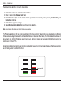
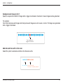
Send post-event image (s) [0~7)
Specify to capture the number of images after a trigger is activated. A maximum of seven images can be generated.
For example:
If both the Send pre-event images and Send post-event images are set to seven, a total of 15 images are generated
after a trigger is activated.
1 pic.
2 pic.
3 pic.
4 pic.
5 pic.
6 pic.
7 pic.
8 pic.
9 pic.
10 pic.
11 pic. 10 pic.
12 pic. 13 pic.
14 pic.
15 pic.
The moment the
trigger is activated.
Add date and time suffix to file name
Select this option to add date and time to the file name suffix.
SNAPSHOTS20080104_100341
File name prefix Date and time suffix
The format is: YYYYMMDD_HHMMSS
D-Link DCS-3110 User Manual
57
Section 4 - Configuration
Maximum duration
Specify the maximal recording duration in seconds. You can set up to ten seconds.
For example:
If the Pre-event recording is set to five seconds and the Maximum duration is set to ten seconds, the Network Camera
continues to record for another four seconds after a trigger is activated.
1 sec.
2 sec.
3 sec.
4 sec.
5 sec.
6 sec.
7 sec.
8 sec.
9 sec.
10 sec.
The moment the
trigger is activated.
File name prefix
Enter the text that will be added at the beginning of the file name.
VIDEOS20080104_100341
File name prefix Date and time suffix
The format is: YYYYMMDD_HHMMSS
D-Link DCS-3110 User Manual
58
Section 4 - Configuration
Add Event
Create and schedule up to 3 events with their own settings here.
Event name: Enter a name for the event.
Enable this Select to activate this event.
event:
Priority: Set the priority for this event. The event with higher priority
will be executed first.
Delay: Select the delay time before checking next event. It is
being used for both events of motion detection and digital
input trigger.
Trigger: The input type that triggers the event.
Video motion Motion is detected during live video monitoring. Select the
detection: windows that need to be monitored.
Periodic: The event is triggered in specified intervals. The unit of
trigger interval is minute.
Digital input: External trigger input to the camera.
System boot: Triggers an event when the system boots up.
Time: Select Always or enter the time interval.
Trigger D/O: Select to trigger digital output for specific number of
seconds when an event occurs.
CF Card: To record media to the CF card when an event is
triggered.
D-Link DCS-3110 User Manual
59
Section 4 - Configuration
Add Recording
Here you can configure and schedule the recording settings.
Recording entry The unique name of the entry.
name:
Enable this Select this to enable the recording function.
recording:
Priority: Set the priority for this entry. The entry with a higher
priority value will be executed first.
Source: The source of stream.
Recording Scheduling the recording entry.
schedule:
Recording Configuring the setting for the recording.
settings:
Destination: Select the folder where will store the recording
file.
Total cycling Please input a HDD volume between 1MB and
recording size: 200GB for recording space. The recording data will
replace the oldest one when total recording size
exceeds this value. For example, if each recording
file is 6MB, and the total cycling recording size is 600MB, then the camera will record 100 files to the specified location (folder)
and then will delete the oldest file and create new file for cycling recording.
Please note that if the HDD empty space is not enough, the recording will stop. Before you setup this option please make
sure your HDD has enough space and it is better to not save other files in the same folder as recording files.
Size of each file File size for each recording file. You may input the value in the range of 200-6000.
for recording:
File Name Prefix: The prefix name will be added on the file name of the recording file(s).
D-Link DCS-3110 User Manual
60
Section 4 - Configuration
Advanced
DI and DO
The I/O connector provides the physical interface for digital output (DO) and digital input (DI) that is used for connecting
such external alarm devices as IR-Sensors and alarm relays to the network camera.
DI and DO: Settings for both Digital input signal and digital
output signal can be configured here.
Digital input Please select High or Low for digital input trigger
trigger condition: condition. When an external device is connected
to the digital input pins, the state of the voltage
will be monitored. (Max. Input 500mA, 12Vdc)
Digital output: Select Grounded or Open to define normal status
of the digital output. The camera will show whether
the trigger is activated or not.
D-Link DCS-3110 User Manual
61
Section 4 - Configuration
RS485
With digital PTZ (Pan/Tilt/Zoom) feature enabled, it is possible to zoom
in and out video recieved from the DCS-3110.
Enable PTZ Operation
To utilize this feature, please connect the DCS-3110 to a PTZ scanner via
RS485 interface and follow the instructions given below. Three PTZ drivers are
supported:
• DynaDome/SmartDOME
• Lilin PIH-7x00
• Pelco D protocol
Note: If none of the above PTZ drivers is supported by your PTZ scanner, please
select Custom camera.
1. Connect to your PTZ scanner, set the Camera ID, PTZ driver, and Port
settings.
2. Select Enable PTZ Operation and then click Save to take effect.
3. The PTZ control buttons will be displayed in the main page.
Preset Position
Click Preset Position to set the preset position for the Network Camera. A total of
20 preset positions can be configured.
To set a preset position, follow the steps given below:
1. Adjust the Network Camera to a desired position using the buttons on the
right side of the window.
2. In the Preset position name text box, enter a descriptive name for the preset
position. You can enter up to 40 characters in the text box.
3. Click Add. The preset position name will appear in the drop-down list.
To remove a preset position from the list, select a preset position name from the
drop-down list and then click Delete.
D-Link DCS-3110 User Manual
62
Section 4 - Configuration
Custom Command
Click Custom Command to open the Custom Command page. In this page, you
can set addition command buttons for controlling the PTZ scanner. A total of five
command buttons can be configured.
To add a new control button, follow the steps below.
1. In the Button name text box, enter the descriptive name for the control
button.
2. Refer to the PTZ scanner and enter the command.
3. Click Save to take effect and click Close to quit this page.
4. The new custom command button will be displayed in the main page.
NOTE :
If Custom camera is selected as the PTZ driver, the PTZ control buttons will not
take effect. Please go to Configuration > Camera control > Custom Command
to set the commands in the Control settings session. Please refer to the user manual of the PTZ scanner for the command.
D-Link DCS-3110 User Manual
63
Section 4 - Configuration
ICR
ICR - IR-Cut Removable(ICR) filter is a switch mechanical design
of two different sensor filters. It provides the best light conditions
both during the day and night. The following options are:
Auto: The Network Camera automatically switches
between day and night mode by judging the level
of ambient light. This mode is accessible only
when the exposure mode is set to Auto.
Day Mode: In this mode the Network Camera switches on
the infrared cut filter at all times, which will block
the infrared light from reaching the sensor so that
the colors are not distorted.
Night Mode: The Network Camera switches off the infrared cut
filter to allow the infrared light to pass through.
This helps the Network Camera to see more
clearly in low light conditions.
Schedule Mode: The Network Camera switches between day and
night mode based on a specific schedule.
Ensure to enter the starting and ending time for
the day mode. Note that the time format is [hh:
mm] and is expressed in 24-hour clock time. By
default, the starting time and ending time of day
mode are set to 07:00 and 18:00.
D-Link DCS-3110 User Manual
64
Section 4 - Configuration
Access List
The Access List page will allow you to configure access permissions for each user.
Allow list: The list of IP addresses that have the access right
to the camera.
Start IP address: The starting IP Address of the devices (such
as a computer) that have permission to access
the video of the camera. Click Add to save the
changes made.
Note: A total of ten lists can be configured for
both columns.
End IP address: The ending IP Address of the devices (such as
a computer) that have permission to access the
video of the camera.
Delete allow list: Remove the customized setting from the Allow
List.
Deny list: The list of IP addresses that have no access right
to the camera.
Delete deny list: Remove the customized setting from the Delete
List.
For example:
When the range of allowed list is set from 1.1.1.0 to 192.255.255.255
and the range of denied list is set from 1.1.1.0 to 170.255.255.255, Only
users’ IP located between 171.0.0.0 and 192.255.255.255 can access
the Network Camera.
D-Link DCS-3110 User Manual
Alowed
List
Denied
List
65
Section 4 - Configuration
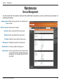
Maintenance
Device Management
You can modify both the camera’s name and the administrator’s password, as well as add more user accounts for
accessing the camera.
Admin password Modify the password for the administrator’s
setup: account.
Add user account: Add a new user account.
Username: Enter a username for the new account.
Password: Enter a password for the new account.
Privilege: Select the access rights for the new user.
Manage user: Manage the accounts for existing users.
Authentication: The access rights for existing users.
Camera Name: Create a unique name for your camera and you
can access the camera using this name in your
web-browser. For example: http://DCS-3110
(by default).
D-Link DCS-3110 User Manual
66
Section 4 - Configuration
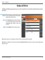
Backup and Restore
The Backup and Restore page will allow you to turn the front panel LED off, restore factory default settings, and reboot
the camera.
Turn off the LED Select this option to turn off the LED next to the
indicator: lens. This will prevent anyone from observing the
operation of the network camera.
Restore: Click the Restore button to reset the camera back
to its factory default settings. This will remove
all the configuration settings that were made
previously.
Reboot: Click the Reboot button to restart the camera.
Note: Please format your CF card before use. All data in the CF card will be erased after formatting.
Note: Before you unplug the CF card from the slot, please select Remove CF card to ensure that your data has been completely stored
before the removal.
D-Link DCS-3110 User Manual
67
Section 4 - Configuration
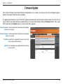
Firmware Update
Your current firmware version and date will be displayed on your screen. You may go to the D-Link Support page to
check for the latest firmware version available.
To upgrade the firmware on your DCS-3110, please download and save the latest firmware version from the D-Link
support site to your local hard drive. Locate the file on your local hard drive by clicking the Browse button. Then, open
the file and click the “Upload” button to start the firmware upgrade.
Current firmware It will be automatically determined and displayed
version: by the system.
Current firmware It will be automatically determined and displayed
date: by the system.
File Path: Locate the file (upgraded firmware) on your hard
drive using the browse feature.
Upload: Start uploading and upgrading the new firmware
to your camera.
D-Link DCS-3110 User Manual
68
Section 4 - Configuration
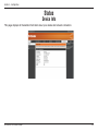
Status
Device Info
This page displays all the details information about your device and network connection.
D-Link DCS-3110 User Manual
69
Section 4 - Configuration
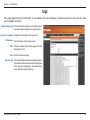
Logs
This page displays the log information of your camera. You can configure a remote log server so that you can view
your log details remotely.
Enable remote log: Click to enable this feature so that the camera
can send camera log files to a remote server.
Log server settings: Configure the settings for the log server.
IP Address: The IP address of the remote server.
Port: The port number of the remote log server. The
default port is 514.
Save: Click to save the settings.
Current Log: The system log file that displayed by the system.
The content of the file reveals useful information
about camera configuration and connectivity
status after the camera boots up.
D-Link DCS-3110 User Manual
70
Section 4 - Configuration
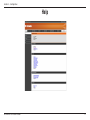
Help
D-Link DCS-3110 User Manual
71
Section 4 - D-ViewCam Installation
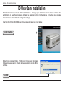
D-ViewCam Installation
D-ViewCam software is included for the administrator to manage up to 32 D-Link network cameras remotely. The
administrator can use the software to configure the advanced settings for the camera. D-ViewCam is a complete
management tool and includes all configurative settings.
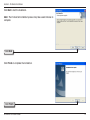
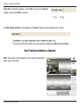
Insert the CD into the CD-ROM drive. A menu screen will appear as shown below.
Click D-ViewCam
D-ViewCam provides English, Traditional Chinese and Simplified
Chinese language versions. Select a language version and click OK to
continue.
Click OK
D-Link DCS-3110 User Manual
72
Section 4 - D-ViewCam Installation
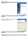
Click Next to continue.
Click Next
Click Browse if you would like to choose a specific folder for the
installation, otherwise click Next to continue.
Click Next
D-Link DCS-3110 User Manual
73
Section 4 - D-ViewCam Installation
Click Next to start the installation.
Note: The D-ViewCam installation process may take several minutes to
complete.
Click Next
Click Finish to complete the installation.
Click Finish
D-Link DCS-3110 User Manual
74
Section 4 - D-ViewCam Installation
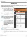
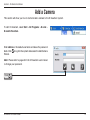
Add a Camera
This section will show you how to start and add a camera to the D-ViewCam system.
To start D-ViewCam, select Start > All Programs > D-Link >
D-Link D-ViewCam.
Enter admin as the default username and leave the password
blank. Click to log into the system and access the Add Camera
Wizard.
Note: Please refer to page 48 in the D-ViewCam user manual
to change your password.
Click
D-Link DCS-3110 User Manual
75
Section 4 - D-ViewCam Installation
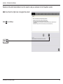
Welcome to the Add Camera Wizard. Use this wizard to add your cameras to the D-ViewCam system.
Note: Use the left or right arrow to navigate the wizard.
Click
to continue.
Click
D-Link DCS-3110 User Manual
76
Section 4 - D-ViewCam Installation
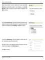
Select which method to add your camera(s). You can select Auto
Discovery to automatically search for your camera(s), or select Add
Manually to add your camera(s) using the camera’s IP address. Click
Next to continue.
If you select Auto Discovery, the system will search all cameras that are
located on the same LAN with same subnet. The system will place all the
cameras at the default map called My Map. Click Next to continue.
If you choose Add Manually, enter the IP address or domain name, http
port, model name, camera ID and password.
Click the “?” button to auto detect the camera’s model name, then the
model name will appear in the Model Name box.
Click Next to continue.
D-Link DCS-3110 User Manual
77
Section 4 - D-ViewCam Installation
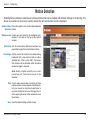
D-ViewCam shows the detected network camera(s) information. You can select the recording mode for each camera.
• 24/7 Continuous Recording: ���������������������������������������������������
Continuously records 24 hours a day, 7 days a week.
• 24/7 Motion Detection Recording: ����������������������������������������������������������������
Continuously monitors, but only records when motion is detected.
• Office Hours Only: Continuously
������������������������������������������������������������������������������������
monitors during office hours (8:00AM to 6:00PM), and only records when
motion is detected.
• Non-Office Hours Only: Continuously
����������������������������������������������������������������������������������������
monitors during non-office hours (6:00PM to 8:00AM), and only records when
motion is detected.
Note: Excluding 24/7 Continuous Recording, all other schedule recording modes can only record when motion is detected. Please refer
to the user manual for more information.
Click Next to continue.
D-Link DCS-3110 User Manual
78
Section 4 - D-ViewCam Installation
Select Yes to add other cameras, or select No if you have no additional
cameras to add. Click Next to continue.
The Add Camera wizard is now complete. Click Close to access the D-ViewCam’s main screen.
Your D-ViewCam Installation is Complete!
Note: Please refer to the D-ViewCam user manual for information
about using D-ViewCam.
D-Link DCS-3110 User Manual
79
Section 5 - Frequently Asked Questions
Frequently Asked Questions
This chapter provides solutions to problems that may occur during the installation and operation of the DCS-3110.
Read the following descriptions if you are having any problems.
Megapixel PoE Network Camera Features
1. What is a Megapixel PoE Network Camera?
The Megapixel PoE Network Camera is a stand-alone system connecting directly to an Ethernet or Fast Ethernet network. The Megapixel
PoE Network Camera differs from a conventional PC Camera because it has an integrated system with built-in CPU and web-based
solutions, providing a low cost solution that can transmit high quality video images for monitoring. The Megapixel PoE Network Camera
can be remotely managed, accessed and controlled using a web browser from any computer over an Intranet or Internet.
2. What is the maximum number of users that can access DCS-3110 simultaneously?
The maximum number of users that can log onto the Megapixel PoE Network Camera at the same time is 10. Please keep in mind the
overall performance of the transmission speed will be reduced if many users have logged on to the camera simultaneously.
There is no limit on the number of users when a multicast-enabled router is being used. The multicast protocol helps reduce the network
bandwidth consumption.
Note that the Network Camera must be configured to enable multicast streaming. For more information, see RTSP Streaming on page
41.
3. What algorithm is used to compress the digital image?
The ������������������������������������������������������������������������������������������������������������������������������
Megapixel���������������������������������������������������������������������������������������������������������������������
PoE Network Camera utilizes MPEG-4 simple profile or MJPEG Mode image compression technology providing high quality
images. MJPEG is a standard for image compression and it can be applied to various web browsers and application software without
installing any extra software
4. Can I capture still images from the Megapixel
�����������������������������
PoE
�������������������
Network Camera?
Yes you can capture still images using the snapshot function.
D-Link DCS-3110 User Manual
80
Section 5 - Frequently Asked Questions
Megapixel PoE Network Camera Installation
1. Can the Network Camera be used outdoors?
The Megapixel PoE Network Camera is not weatherproof. It needs to be equipped with a weatherproof case for outdoor use but it is not
recommended.
2. When physically connecting the Network Camera to a network, what network cabling is required?
The Megapixel PoE Network Camera uses Category 5 UTP cable allowing 10 Base-T and 100 Base-T networking solutions.
3. Can the Network Camera be setup as a PC-cam on a computer?
No, the Megapixel PoE Network Camera is used only on an Ethernet or Fast Ethernet network. The D-Link DSB-C110, DSB-C310, can
be used as a PC Camera (Webcam).
4. Can the Network Camera be connected to the network if it consists only of private IP addresses?
Yes, the Megapixel PoE Network Camera can be connected to a LAN using only a private IP address.
5. Can the Network Camera be installed and work if a firewall exists on the network?
If a firewall exists on the network, port 80 is open for ordinary data communication. The DCS-3110 uses port 5002 for streaming audio
and port 5003 for streaming video. These ports (or the ports you have specified in the Setup Tab in the Configuration screen) need to be
opened on the firewall.
6. Why am I unable to access the Network Camera from a web browser?
If a router or firewall is used on the network, the correct ports for the DCS-3110 may not be configured on the router or firewall. To correct
the problem, you need to determine if the DCS-3110 is behind a router or firewall and if the router or firewall is properly configured for
the ports the DCS-3110 is using. Refer to Page 40 for help in opening the correct ports on a router or firewall for use with the DCS-3110.
Other possible problems might be due to the network cable. Try replacing your network cable. Test the network interface of the product by
connecting a local computer to the unit. If the problem is not solved, the Megapixel PoE Network Camera might be faulty.
7. Why does the Network Camera work locally but not externally?
• This might be caused by network firewall protection. The setting of the firewall may need to be changed in order for the Megapixel PoE
Network Camera to be accessible outside of your local LAN. Check with the Network Administrator for your network.
• Make sure that your Megapixel PoE Network Camera isn’t conflicting with any Web server you may have running on your network.
• The default router setting might be a possible reason. Check that the configuration of the router settings allows the Megapixel PoE
Network Camera to be accessed outside of your local LAN.
D-Link DCS-3110 User Manual
81
Section 5 - Frequently Asked Questions
8. I connected the Network Camera directly to a computer with a cross-over Ethernet cable and received a
Windows error upon running the installation Wizard?
• This Windows error will occur if the Megapixel PoE Network Camera is connected to a computer that is not properly configured with a
valid IP address. Turn off DHCP from the Network Settings in Windows and configure the computer with a valid IP address or connect
the camera to a router with DHCP enabled.
• This error can also occur if the Installation Wizard icon had been clicked more than once from the setup wizard.
9. Noisy images occur. How can I solve the problem?
The video images might be noisy if the Megapixel PoE Network Camera is used in a very low light environment. To solve this issue you
need more lighting.
10. The images appear to be of poor quality, how can I improve the image quality?
• Make sure that your computer’s display properties are set above 256 colors. Using 16 or 256 colors on your computer will produce
dithering artifacts in the image, making the image appear to be of poor quality.
• The configuration on the Megapixel PoE Network Camera image display is incorrect. Through the Setup > Image Setup section of the
Web management you need to adjust the image related parameters such as brightness, white balance and power line frequency for
fluorescent light.
D-Link DCS-3110 User Manual
82
Appendix A - Networking Basics
Networking Basics
Check your IP address
After you install your new D-Link adapter, by default, the TCP/IP settings should be set to obtain an IP address from a
DHCP server (i.e. wireless router) automatically. To verify your IP address, please follow the steps below.
Click on Start > Run. In the run box type cmd and click OK. (Windows Vista® users type cmd in the Start Search
box.)
At the prompt, type ipconfig and press Enter.
This will display the IP address, subnet mask, and
the default gateway of your adapter.
If the address is 0.0.0.0, check your adapter
installation, security settings, and the settings
on your access point. Some firewall software
programs may block a DHCP request on newly
installed adapters.
If you are connecting to a wireless network at a hotspot (e.g. hotel, coffee shop, airport), please contact an employee
or administrator to verify their wireless network settings.
D-Link DCS-3110 User Manual
83
Appendix A - Networking Basics
Statically Assign an IP address
If you are not using a DHCP capable gateway/access point, or you need to assign a static IP address, please follow
the steps below:
Step 1
Windows Vista® - Click on Start > Control Panel > Network and Internet > Network and Sharing Center > Manage
Network Connections.
®
Windows XP - Click on Start > Control Panel > Network Connections.
Step 2
Right-click on the Local Area Connection which represents your D-Link network adapter and select Properties.
Step 3
Highlight Internet Protocol (TCP/IP) and click Properties.
Step 4
Click Use the following IP address and enter an IP address that is on the same
subnet as your network or the LAN IP address on your access point.
Example: If the network camera’s LAN IP address is 192.168.0.1, make your IP
address 192.168.0.X where X is a number between 2 and 99. Make sure that the
number you choose is not in use on the network. Set Default Gateway the same
as the LAN IP address of your access point (192.168.0.1).
Set Primary DNS the same as the LAN IP address of your access point (192.168.0.1).
The Secondary DNS is not needed or you may enter a DNS server from your
ISP.
Step 5
Click OK to save your settings.
D-Link DCS-3110 User Manual
84
Appendix B - Reset and Restore
Reset and Restore
There is a button hidden in the pinhole beside the Ethernet socket. It is used to reset the system or restore the factory
default settings. Sometimes resetting the DCS-3110 will return the system back to a normal state. If the system still
has problems after reset, restore the factory settings and install again:
RESET:
1. Lightly insert a paper clip (or a similar sized tool) into the reset
hole on the back of the camera, press lightly and then release the
button.
2. The LED on the front of the camera will begin blinking red and
green.
Reset button
3. When the LED stops the blinking the reset has completed.
RESTORE:
1. Insert the paperclip or other tool and hold the button in.
2. Wait for the LED on the front of the camera to blink red and green
and hold the button for 30 seconds.
Restoring the factory defaults will result in
the loss of any previous settings and will
require running the Installation Wizard to
return the DCS-3110 to a normal state.
3. Withdraw the tool after the second cycle of the LED blinking and
a factory restore has been completed.
D-Link DCS-3110 User Manual
85
Appendix B - External I/O Port
External I/O Port
DI/DO Diagram
Pin 1~4 are used to connect with digital input and digital output devices.
Refer to the following illustration for connection method.
12V
PIN 1
DO+
Power+12V
The DCS-3110 provides a general I/O terminal block with one digital
input and one relay switch for device control. The
����������������������������
relay switch of DO+ and
DO- can be used to turn on or off the external device. �������������������
DI+ and DI- can be
connected to an external sensor and the state of voltage will be monitored
from the initial state ‘LOW’.
The I/O connector provides the physical
interface for digital output (DO) and digital
input (DI) that is used for connecting a
diversity of external alarm devices to the
Network Camera such as IR-Sensors and
alarm relays.
PIN 2
DODigital output
+12V
DI+
PIN 3
Digital input
PIN 4
DIGround
External I/O Port
The digital input is used for connecting external alarm devices and once
triggered images will be taken and e-mailed.
D-Link DCS-3110 User Manual
86
Appendix C - Technical Specifications
Technical Specifications
Network Protocol Support
SENSOR & LENS SPECIFICATIONS
• IPv4, TCP/IP, RTSP/ RTP/ RTCP, HTTP, SMTP, FTP, NTP, DNS, DHCP, UPnP,
DDNS,PPPoE, IGMP, Samba client, IP Filtering, 3GPP
•
•
•
•
Built-in Network Interfaces
1/4” 1.3mega-pixel progressive color CMOS sensor
6 mm megapixel lens, F1.6
Removable IR-cut filter: Auto/Schedule/Manual
Minimum illumination: 1.5 Lux, F2.0
• 10/100BASE-TX Ethernet port, RJ45
Video Algorithm Support
•
•
•
•
•
•
•
•
JPEG for still image
Compression: MJPEG & MPEG-4
Streaming: Simultaneous dual-streaming
MPEG-4 streaming over UDP, TCP, or HTTP
MPEG-4 multicast streaming
MJPEG streaming over HTTP
Supports 3GPP mobile surveillance
Camera live viewing for up to 10 clients
Video Resolution
•
•
•
•
•
•
MJPEG video with resolution up to 1280x1024 (1.3 Megapixel)
MPEG-4 video with resolution up to 640x480 (VGA)
Up to 30fps at 176 x 144
Up to 30fps at 320 x 240
Up to 30fps at 640 x 480
Up to 8 frames at 1280x1024
AUDIO
• Compression and bit rate:
GSM-AMR speech compression, bit rate: 4.75 kbps ~12.2 kbps
MPEG-4 AAC audio encoding, bit rate: 16 kbps ~128 kbps
• Interface: Built-in microphone, external microphone input, external speaker output
• Supports two-way audio by SIP protocol
• Supports hardware and software audio mute
EVENT MANAGEMENT
•
•
•
•
•
Motion detection weekly schedule
Event notification and upload snapshots/video clips via using HTTP, SMTP, or FTP
Multiple HTTP, SMTP, or FTP server setup
Multiple event notification setups for flexible application
Multiple recording methods for easier backup
SECURITY
Video Features
• Administrator and user group protected
• Password authentication
• HTTP and RTSP digest encryption
•
•
•
•
•
•
SURVEILLANCE SOFTWARE FUNCTIONS
• Remote management/control of up to 32 cameras
• Viewing of up to 32 cameras on one screen
• Supports all management functions provided in web interface
• Scheduled motion triggered, or manual recording options
Adjustable image size, quality, and bit rate
Time stamp and text overlays
3 configurable motion detection windows
Flip & mirror
Configurable brightness
AGC, AWB, AES
Video Bit Rate
• 20K to 4M
D-Link DCS-3110 User Manual
REMOTE MANAGEMENT
• Configuration accessible via web browser
• Take snapshots/video clips and save to CF card, local hard drive or NAS via web
browser
87
Appendix C - Technical Specifications
SYSTEM REQUIREMENTS
• Operating System: Microsoft Windows® XP/Vista
• Browser: Internet Explorer, Firefox, Netscape, Mozilla, Opera browser
POWER CONSUMPTION
• Max 4 W
DIMENSIONS
• 80 (W) X 143.8 (D) X 62 (H) (mm)
SUPPORTED PDA, MOBILE PHONES & SOFTWARE
Handsets with 3GPP player
• Packet Video Player 3.0
• QuickTime 6.5
• Real Player 10.5
WEIGHT
• 521 gm
OPERATION TEMPERATURE
• 0º to 40º C (32º to 104º F)
PHYSICAL & ENVIRONMENTAL
LAN
•
•
•
•
•
IEEE 802.3 compliance
IEEE 802.3u compliance
Support Full-Duplex operations
802.3x Flow Control support for Full-Duplex mode
Supported IEEE 802.3af standard (PoE)
FRONT-END STORAGE
• CF card slot for local recording of MP4 file
STORAGE TEMPERATURE
• -20º to 70º C (-4º to 158º F)
HUMIDITY
• 20% to 80% non-condensing
EMISSION (EMI), SAFETY & OTHER CERTIFICATIONS
• FCC
• CE
• C-Tick
EXTERNAL DEVICE INTERFACE
• One D/I and one D/O for external sensor and alarm
• RS485 interface for external scanner
• DC12V output for external accessory
DIAGNOSTIC LED
• 2 color LED
POWER INPUT
• 100-240Vac, 50/60Hz, 12V, 1.25Adc.
The mobile device must have 3G support and subscribe to 3G service from the phone service
provider. The playback device must be equipped with 3G video playback such as RealPlayerTM
or PacketVideoTM.
1
D-Link DCS-3110 User Manual
88