1
Chapter 8
TTL Control
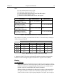
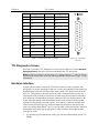
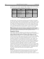
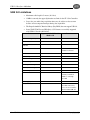
Pin #
Assignment
Pin #
87
Assignment
1
IN 1
14
IN 2
2
IN 3
15
IN 4
3
IN 5
16
IN 6
4
IN 7
17
IN 8
5
GND
18
GND
6
EN/CLK
19
Reserved
7
(future use)
20
GND
8
GND
21
OUT 2
9
OUT 1
22
OUT 4
10
OUT 3
23
OUT 6
11
OUT 5
24
OUT 8
12
OUT 7
25
GND
13
Reserved
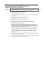
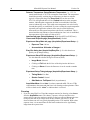
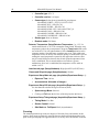
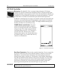
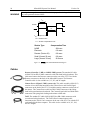
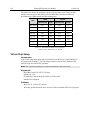
Table 11. TTL In/Out Connector Pinout
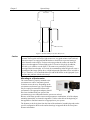
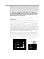
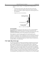
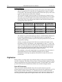
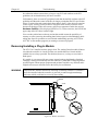
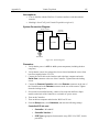
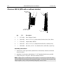
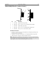
Figure 44. TTL In/Out
Connector
TTL Diagnostics Screen
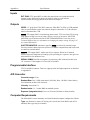
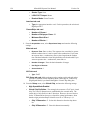
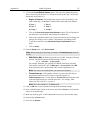
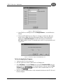
WinView/32 provides a TTL Diagnostics screen (located in WinView/32 under Hardware
Setup|Diagnostics) that can be used to test and analyze the TTL In/Out lines.
Note: In WinView software versions prior to 1.6, Output Lines 5, 6, 7, and 8 are shown
checked in the default state, incorrectly indicating that their default state is logic 1 in the
MicroMAX.
Hardware Interface
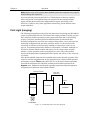
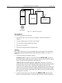
A cable will be needed to connect the TTL In/Out connector to the experiment. The
design will vary widely according to each user’s needs, but a standard 25-pin female type
D-subminiature connector will be needed to mate with the TTL In/Out connector at the
ST-133A. The hardware at the other end of the cable will depend entirely on the user’s
requirements. If the individual connections are made using coaxial cable for maximum
noise immunity (recommended), the center conductor of the coax should connect to the
proper signal pin and the cable shield should connect to the nearest available ground
(grounds are conveniently provided at pins 5, 8, 18 and 20). Connector hardware and
cables of many different types are widely available and can often be obtained locally,
such as at a nearby Radio Shack® store. A list of possibly useful items follows. Note that,
although the items listed may be appropriate in many situations, they might not meet
your specific needs.
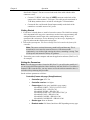
•
25-pin female type D-subminiature solder type connector (Radio Shack part no 2761548B).