1
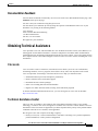
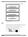
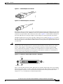
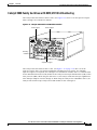
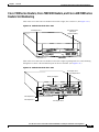
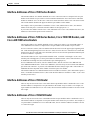
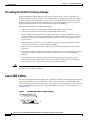
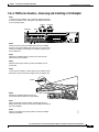
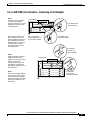
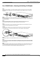
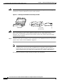
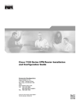
Chapter 3
Removing and Installing Port Adapters
Connecting PA-FE-TX and PA-FE-FX Port Adapter Interface Cables
The ferrite bead prevents electromagnetic interference (EMI) from affecting the PA-FE-TX-equipped
system and is a required component for proper system operation.
Figure 3-4
Attaching the Ferrite Bead around the RJ-45 Cable
Ferrite bead
Caution
Step 3
RJ-45 cable
with ferrite bead
H4202
Caution
To prevent problems on your PA-FE-TX and PA-FE-FX and network, do not simultaneously connect
RJ-45 (or SC) and MII cables to one PA-FE-TX and PA-FE-FX. On a single PA-FE-TX and
PA-FE-FX, only one network connection can be used at one time. Only connect cables that comply
with EIA/TIA-568 standards.
Attach the network end of your RJ-45 (or SC) or MII cable to your 100BASE-T transceiver, switch, hub,
repeater, DTE, or other external 100BASE-T equipment.
Note
After your MII transceiver is connected and the PA-FE-TX and PA-FE-FX interface is
configured as up, you can verify that your MII transceiver responds to physical sublayer
(PHY) address 0 by disconnecting the transceiver from the MII receptacle; if the PA-FE-TX
and PA-FE-FX interface goes down, then your MII transceiver responds to PHY address 0.
This completes the PA-FE-TX and PA-FE-FX port adapter cable installation.
Cisco PA-FE-TX and Cisco PA-FE-FX Fast Ethernet 100BaseT Port Adapter Installation and Configuration
3-14
OL-2899-02