1
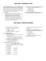
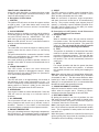
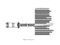
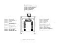
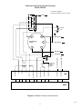
A
®
AUTOMATIC ENGINE CONTROLLERS
MODELS A88 AND A88-F
INSTALLATION MANUAL
A88-8916N
Revised 01-97
Section 40
(00-02-0196)
TABLE OF CONTENTS
SECTION
PAGE
I
INTRODUCTION
1
II
IIA
IIB
IIC
SPECIFICATIONS
Power Requirements
Input Requirements
Output Ratings
1
1
1
1
III
IIIA
IIIB
FRONT PANEL DESCRIPTION
Description of LED Callouts
Description of AOT Switch, Crank Disconnect
Control & Rest/Crank Time Control
2
3
IV
OPTIONAL HOOKUPS
4
V
OPERATION
5
3
LIST OF ILLUSTRATIONS
TYPE
DESCRIPTION
PAGE
Illustration
Illustration
Diagram 1
Diagram 2
Diagram 3
Diagram 4
Diagram 5
Diagram 6
Face Plate, A88 and A88-F
Optional Hookup Schemes
Basic Wiring Hookup, A88
A88 Wiring Harness
Basic Wiring Hookup, A88-F
A88-F Wiring Terminals
Wiring for Honda Generator EM3500SX/EM5000SX
Wiring for Honda Generator CXS360
2
4
6
7
8
9
10
11
In order to consistently bring you the highest quality, full featured products, we reserve the right to change our specifications and designs at any time.
®
FRANK W.
Since 1939
MFR.
■ Frank W. Murphy Manufacturer
P.O. Box 470248; Tulsa, Oklahoma 74147; USA
tel. (918) 627-3550 fax (918) 664-6146
e-mail [email protected]
■ Frank W. Murphy Southern Division
P.O. Box 1819; Rosenberg, Texas 77471; USA
tel. (281) 342-0297 fax (281) 341-6006
e-mail [email protected]
Printed in U.S.A.
■ Frank W. Murphy, Ltd.
Church Rd.; Laverstock, Salisbury SP1 1QZ; U.K.
tel. +44 1722 410055 fax +44 1722 410088 tlx 477088
e-mail [email protected]
■ Frank W. Murphy Pte., Ltd.
26 Siglap Drive; Republic of Singapore 456153
tel. +65 241-3166 fax +65 241-8382
e-mail [email protected]
■ Murphek Pty., Ltd.
1620 Hume Highway; Campbellfield, Vic 3061; Australia
tel. +61 3 9358-5555 fax +61 3 9358-5558
■ Murphy de México, S.A. de C.V.
Blvd. Antonio Rocha Cordero 300, Fracción del Aguaje
San Luis Potosí, S.L.P.; México 78384
tel. +52-48-206264 fax +52-48-206336
e-mail [email protected]
■ Murphy Switch of California
P.O. Box 900788; Palmdale, California 93590; USA
tel. (805) 272-4700 fax (805) 947-7570
e-mail [email protected]
■ Frank W. Murphy France
tel. +33 1 30 762626 fax +33 1 30 763989
WARNING
BEFORE BEGINNING
INSTALLATION OF THIS
MURPHY PRODUCT
✔ Disconnect all electrical
power to the machine.
✔ Make sure the machine
cannot operate during
installation.
✔ Follow all safety warnings of
the machine manufacturer.
✔ Read and follow all
installation instructions.
SECTION I: INTRODUCTION
A. The Automatic Engine Controller, Model A88 and
A88-F is designed to automatically start, monitor and stop
electric start engines. The A88 comes in an all-weather
case with a 5 foot cable and a plug for connection. The
A88-F is the same system, but housed in a panel-mount
case with terminals on back for connecting.
8. Crank disconnect circuitry accepts the following inputs:
a. breaker or electronic type ignition
b. magnetic pickup
c. alternator tach
d. flywheel alternator
e. mechanical switch
9. Has a built-in one minute time delay for customer use.
10. Five fixed crank attempts before shutdown.
B. Features
1. Has a self-contained Auto-Off-Test Switch.
2. Rest and crank time selected by a single switch.
3. Adjustable crank disconnect speed switch.
4. Close a switch to run; open to stop feature.
5. Engine starts and runs when a contact closes and
stops when a separate set of contacts close.
6. Goes into a rest period in the event of a false start.
7. Alarm before start to alert personnel.
SECTION II: SPECIFICATIONS
A. Power Requirements:
1. Voltage 8-30 VDC, negative ground.
2. Current @ 12 volts less load current.
a. standby
10 ma
b. crank
140 ma
c. shutdown 32 ma
3. Maximum fuse size, 4 amp, slow blow.
11. An output to indicate that the engine is running
to be used as remote indication or in warm up
operation.
12. Has a summary of shutdown output.
13. Monitors the following engine functions and will
shut the engine down in event of a failure:
a. Overcrank
b. Oil Pressure
c. Engine Temperature
d. Spare
14. Has 30 second lockout feature for start up.
15. Output for choke actuator.
B. Input Requirements:
1. Start-stop control switch
a. SPST N.O. dry contact; close to run, open to stop
b. SPDT dry contact
c. Two SPST N.O. dry contacts; one, momentary
close to run; one momentary close to stop
2. Magnetic pickup or alternator tach requirements:
a. voltage 2 volts, rms minimum
b. 25 to 2000 hz crank disconnect
c. maximum 100 volts Pk Pk
C. Output Ratings: Source = switch to battery
Sink = switch to ground
1. Ignition or run relay; SPDT dry relay contacts
rated 10 amp @ 30 VDC resistive, 6 amp @ 30
VDC inductive.
2. Crank output
a. transistor
1 amp source
b. transistor
1 amp sink
3. Choke
a. transistor
1 amp sink
4. Time delay
a. transistor
1 amp sink
5. Summary
a. transistor
1/2 amp sink
1
SECTION III: FRONT PANEL DESCRIPTION
IGNITION
ON
CHOKE
PICK UP
PRESENT
OVER
CRANK
CRANK
OIL
PRESSURE
CRANK
DISCONNECT
ENGINE
TEMP.
A88
Automatic
Engine
Controller
CRANK
DISCONNECT
AUTO
(Shown without enclosure)
5s
10s
OFF
TEST
15s
20s
CRANK
AND
REST
TIME
A88-F
Automatic
Engine
Controller
IGNITION
ON
CHOKE
PICK UP
PRESENT
OVER
CRANK
CRANK
OIL
PRESSURE
CRANK
DISCONNECT
ENGINE
TEMP.
CRANK
DISCONNECT
AUTO
OFF
TEST
5s
10s
15s
(Shown without enclosure)
20s
2
CRANK
AND
REST
TIME
FRONT PANEL DESCRIPTION
Along with each description, an attempt has been made
to clarify output and input connections according to their
functions and terminals or wire color.
A. Description of LED Callouts
1. IGNITION
The ignition LED will come on when the system receives
a signal to start. If the alarm before start is used, this
ignition LED will NOT come on until the 5 second alarm
goes off.
9. SPARE
This LED comes on to indicate cause of shutdown if the
spare is used. Connect the monitor to Terminal 13 of the
A88-F and the yellow/white wire of the A88.
Note: the overcrank, oil pressure, engine temperature
and spare circuits are locked out for 30 seconds during
start up. They require normally open sensors (close to
operate). A summary output is available (Terminal 20 on
the A88-F and the brown wire of the A88.) for remote
indication when a shutdown occurs.
2. PICKUP PRESENT
When the engine is cranking or running and the pickup is
connected properly with sufficient output voltage (2 volt
rms) this LED will come on. IMPORTANT - This LED
must come on or the unit will not operate properly.
Note: this LED will NOT be on if a mechanical switch is
used as a crank disconnect sensor.
B. Description of AOT Switch, Crank Disconnect
Control & Rest/Crank Time Control
1. AUTO-OFF-TEST
a. OFF
When a shutdown occurs, this unit must be removed
from power to reset. The Auto-Off-Test switch removes
power when placed in the off position. The green LED
will go off. The unit should be left off 8-10 seconds
to allow the circuitry to discharge and stabilize.
b. TEST
This position is used after all connections have been
made or for periodic checks that should be a part of a
preventive maintenance program. The start and stop
inputs are by-passed when this switch is placed in the
test position. The unit will automatically initiate the
crank cycle.
c. AUTO
For normal operation and after the system has been
tested, Place the switch in this position. It indicates
the controller will take over starting and stopping the
engine.
Note: these units may have a 4-5 second alarm before start.
The A88-F comes with the alarm hooked up by connection
of terminals 16 and 17. The A88 comes without the alarm
hooked up; if alarm is needed, ground the red/white wire.
Although it is an optional hook up, it is recommended that
this alarm be used to alert personnel of a start.
3. CRANK
The crank LED is on when the engine is cranking and is
used to show that the crank circuitry is functioning
properly.
The crank solenoid will be connected to terminal 1 of the
A88-F or the white/brown wire of the A88, if the solenoid
is connected to positive to operate.
If the crank solenoid is grounded to operate, connect it to
terminal 2 of the A88-F or connect it to the white/red wire of
the A88.
4. CRANK DISCONNECT
This LED comes on when the crank disconnect
adjustment is adjusted to disengage the starter. When
this LED comes on, the crank LED goes out. (See item B2 for control setting adjustments)
5. CHOKE
This LED will come on for approximately 3-4 seconds at
the beginning of each crank cycle and then go out. If a
choke or compression release solenoid is connected from
battery positive to Terminal 3 (A88-F)or the violet wire
(A88) it will be energized when the LED comes on.
2. CRANK DISCONNECT CONTROL
Adjust this control to make the crank circuit disengage the
starter when the engine starts. Rotating it counterclockwise makes the starter drop out at lower RPM.
6. OVERCRANK
If the engine is called on to start and fails after 5 tries, this
LED will come on and stay on to indicate cause of
shutdown.
3. REST AND CRANK TIME
By placing this switch in one of the 4 positions, the rest
and crank time is selected. If the switch is placed in the
10 seconds position, the system will crank the engine for
10 seconds, then rest for 10 seconds.
Note: if the engine starts momentarily, then dies, it will go
into a 25-30 second rest period before it attempts another
crank. This is regardless of what position the crank and
rest switch is in.
When the system is called on to crank the first crank cycle
will be typically 50% longer than the remaining four tries.
This feature will aid in starting a cold engine.
7. OIL PRESSURE
The oil pressure LED will come on if oil pressure is lost
during operation and remain on to indicate cause of
shutdown. Terminal 11 of the A88-F or the black/white
wire of the A88 are connected to the oil pressure switch.
8. ENGINE TEMPERATURE
If the unit is shutdown because of high engine temperature,
this LED will be on. The temperature sensor is connected to
Terminal 12 of the A88-F or the blue/white wire of the A88.
3
SECTION IV: OPTIONAL HOOKUPS
In this section the terms Sink and Source are used.
Sink: This terms refers to an output that switches to
ground to do work.
3. CRANK CONNECTIONS
A88-F
Terminal
Lamp
Switch
Terminal
Lamp
Choke
No. 3
Violet
Sink
A88
Wire color
Output
Operation
Summary
No. 20
Brown
Sink
Solenoid
to Ground
Source
B Crank
No. 2
White/Red
Solen. to
batt. pos.
Sink
1A
1A
No. 18
Yellow
After 30
sec. delay
Sink
Max.
Current
1A
5. WARM UP
If it is desirable to have a warm up period or a 90 second
delay after the engine has started, connect the engine
running output to the time delay input and then connect
the time delay to the gas feed or clutch mechanism.
Terminal 18 to terminal 9 on the A88-F, the yellow wire to
the violet/white wire on the A88 unit.
Connect the clutch or gas feed solenoid to battery positive
then to the time delay output terminal 19 on the A88-F;
the orange wire on the A88.
After the engine starts and has been running for approximately 90 seconds, the clutch or gas feed will be energized.
Max.
Current
1/2
A88-F
Output
A88 Wire color
Terminal
Operation
After the engine has been running for approximately 30
seconds, the indicator will be energized.
Max.
Current
2. SUMMARY
For a remote shutdown or alarm feature after a shutdown
occurs, connect the alarm or lamp to the battery positive
then to the terminal or wires shown:
A88-F
Terminal
White/Brown
Engine
Running
At the beginning of each crank cycle, the choke or
compression release solenoid will pull in, remain in for 3
or 4 seconds. The maximum current this circuit can carry
is 1 amp.
Output
No. 1
Output
1. CHOKE
To use this feature, connect the choke or compression
release solenoid to the battery positive and then to the
terminal or wire shown:
A88-F
Output
A88 Wire color
Terminal
Operation
A Crank
4. ENGINE RUNNING
If it is desirable to know or indicate when the engine is
actually running, connect the indicator to the battery
positive and then as below:
Terminal
Output
Output
Max.
Operation Current
If the crank solenoid is already connected to ground,
connect to the unit as indicated in "A" above.
If the crank solenoid is already connected to the battery
positive, connect it as in "B" above.
Source: This term will be used to refer to an output that is
switched to positive to do work.
Switch
A88 wire color Connected
A
4
SECTION V: OPERATION
Refer to Diagrams 1 and 3: Basic Wiring Hookup for
correct connections to your engine.
Diagram 2 shows wire colors that correspond to the A88
plug and hookup wire, in the event of two colors the first
color is the primary color and the other is a tracer color.
Diagram 4 identifies the A88-F wiring terminals.
Step No. 8, Clutch or Warmup Operation:
If a warm up feature is desired see Section IV:
Optional Hookups paragraph 5 WARM UP.
A88
Clutch activates approximately 90 seconds after
engine has started—pulls in after engine stops.
A88-F
18
Step No. 9, Crank disconnect adjustment:
To adjust the crank disconnect, disconnect the ignition
wire or leave the fuel cut off. That will let the engine
crank but not start.
Turn the crank disconnect control fully clockwise (15
turns). This control does not have a stop and it does
not hurt it to turn it more than 15 turns.
Place the the crank and rest time switch in the 10 or
15 second position. Switch the controller in the test
position. With the engine cranking, rotate the control
counter-clockwise until the starter drops out. Notice
that the engine will crank longer the first time.
When the starter kicks out, rotate the control clockwise for approximately 1(one) turn. The crank
disconnect is now set.
Step No. 7, Time Delay:
This system has a 60 second built-in time delay for
customer use. If the appropriate inputs are grounded, it
times out after the crank disconnect light comes on.
Orange wire
Sinks to ground
A88-F ground
Terminal 9
60
seconds
Terminal 19
Sinks to ground
19
Clutch activates approximately 90 seconds after
engine has started—pulls in after engine stops.
Step No. 6, Shutdown:
Connect the shutdown circuits. The spare should be
marked or labeled on the blank space.
60
seconds
Slave
Relay
Diode
9
Step No. 5, Choke:
If a choke or pressure release feature is needed connect the choke solenoid to battery positive then to
terminal 3 of the A-88-F or to the violet wire of the A-88.
A88 ground
violet/white wire
To
Clutch
Control
Batt.+
Step No. 4, Start/Stop
Select the type of Start/Stop control needed and wire
accordingly. If a close to run and open to stop is used
be sure and connect the brown/white and the
grey/white together. On the A-88-F connect terminals
16 and 17. It is recommended that the alarm before
start be used for safety.
Output
Orange
Violet/White
Step No. 3, Ignition:
The type of ignition must be determined and wired
accordingly. Most later models will be of the CDI type.
Delay
Slave
Relay
Diode
Step No. 2, Starter Solenoid:
Determine the type of starter solenoid used on your
engine. In most cases it will be of the source type, that
is, one side of the pull in coil is connected to ground and
and the other has to be connected through the ignition
to positive. Do not connect the controller output directly
to the starter, always use a starter slave solenoid.
Input
Batt.+
Yellow
Step No. 1, Pickup:
Determine the type of pickup to be used and connect
it to the controller as illustrated in the basic wiring
hookup.
To
Clutch
Control
NOTE: When installing relays or solenoids that are
controlled by this controller always install a diode directly
across the coil windings to help eliminate the back EMF.
+
Diode
5
Solenoid
or
Coil
Starter Solenoid Connection
Use Only One, 1 amp max
Pickup Signal Source Connection
Use Only One
To Batt. +
A88
Mini Auto
Starter
Remote Annunciator Connection
1 amp max
To Batt. +
To Batt. +
To Batt. +
N
S
1 2 3
To Starter
To Starter
Magnetic
Pickup
A88 cable
Fly Wheel
ALT.
Electronic or
Breaker Type
Ignition
Tach O/P
ALT
Solenoid
Switched to
Positive(source)
Solenoid
Switched to
Ground(sink)
Vacuum
Switch
Engine
Running
Shutdown
Summary
Blk 18 GA
Red 18 GA
Grey
Blue
Battery
White/Black
Green
SWICHGAGE® Inputs
Oil
White/Red
White/Brown
Black/White
6
Yellow
Brown
Green/White
Temperature
Brown/White
Grey/White
Blue/White
N.O.
White/Orange
C
White/Yellow
N.C.
Wht/Yel
Wht/Ong
Spare
Red/White
White
To Batt. +
Wht/Ong
White
For Momentary
Type Operation
Close to Run
Open to Stop
SPST
Violet/White
Yellow/White
Orange
Violet
Choke Connection
Pulls in for 3-4 sec.
Grn/Wht
To Batt. +
Load
1/2 A
Grounding
Violet/White
will cause Orange
to Grnd 60 sec Later
For Momentary
Type Operation
SPDT
Ignition Connection
CDI Type 6 amp max
Ground to Kill
Ignition Connection
Breaker Type, 6 amp max
Ignition Connection
(Use only one)
Brown/White
Grey/White
Brn/Wht
Stop
Connect
Red/White ground for
5 seconds Alarm On Start
NOTE: First is color of wire, second color is tracer.
EXAMPLE: (White/Red)
White is color, Red is trace color
Diagram 1: A88 Basic Wiring Hookup
Grn/Wht
Start
Grey/White No Connection
Red/White ground for
5 seconds Alarm On Start
Start/Stop Control Connection
(Use only one)
Diagram 2: A88 Wiring Harness
7
Pin 1-wire-Wht/Blk: Breaker ignition I/P
Pin 2-wire-Green: Vacuum switch I/P
Pin 3-wire-Viol/Wht: Grnd for time delay I/P
Pin 4-wire-Grey: Magnetic pickup I/P
Pin 5-wire-Blue: Tach alternator I/P
Pin 6-wire-Violet: Choke (sink) O/P
Pin 7-wire-Wht/Red: Crank (sink) O/P
Pin 8-wire-Yellow: Engine running (sink) O/P
Pin 9-wire-Grn/Wht: Start I/P
Pin 10-wire-Red/Wht: Connect #11 for alarm
Pin 11-wire-Ong/Wht: Connect #10 for alarm
Pin 12-wire-Black: Battery negative (–)
Pin 13-wire-Red: Battery positive (+)
Pin 14-wire-Brn/Wht: Stop I/P
Pin 15-wire-Grey/Wht: Connect to #14 for close to
run-open to stop operation
Pin 16-wire-Wht/Brn: Crank (source) O/P
Pin 17-wire-Yel/Wht: Spare I/P
Pin 18-wire-Blue/Wht: Water temp. I/P
Pin 19-wire-Blk/Wht: Oil pressure I/P
Pin 20-wire-Brown: Shutdown summary (sink) O/P
Pin 21-wire-Wht/Ong: Ignition relay Common
Pin 22-wire-White: Ignition relay N.O.
Pin 23-wire-Wht/Yel: Ignition relay N.C.
Pin 24-wire-Orange: Time delay (sink) O/P
Starter Solenoid Connection
Use Only One, 1 amp max
Use Continuous Duty Solenoid
Pickup Signal Source Connection
Use Only One
To Batt. +
A88-F
Mini Auto
Starter
Remote Annunciator Connection
1 amp max
To Batt. +
To Batt. +
To Batt. +
N
S
1 2 3
To Starter
To Starter
Magnetic
Pickup
Fly Wheel
ALT.
Tach O/P
ALT
Electronic or
Breaker Type
Ignition
Vacuum
Switch
Solenoid
Switched to
Positive(source)
Solenoid
Switched to
Ground(sink)
Engine
Running
Shutdown
Summary
25
26
6
7
Battery
5
8
SWICHGAGE® Inputs
Oil
2
1
8
18
20
11
4
Temperature
17
16
15
12
NO
23
C
21
NC
22
Spare
To Batt. +
For Momentary
Type Operation
Close to Run
Open to Stop
For Momentary
Type Operation
SPDT
SPST
9
13
19
To Batt. +
Stop
Time Delay
Output
Load
1/2 A
3
Choke Connection
Pulls in for 3-4 sec.
Grounding 9
will cause 19 to ground
60 seconds Later
Ignition Connection
CDI Type 6 amp max
Ground to Kill
Connect
Ignition Connection
Breaker Type, 6 amp max
Ignition Connection
(Use only one)
Ground for 5 seconds
Alarm On Start
Diagram 3: A88-F Basic Wiring Hookup
Start
16 No Connection
Ground for 5 seconds
Alarm On Start
Start/Stop Control Connection
(Use only one)
Terminal 21: Common
Terminal 22: Normally Closed (N.C.)
Terminal 23: Normally Open (N.O.)
Terminal 24: No Connection
Terminal 25: Negative (–)
Terminal 26: Positive (+)
Terminal 11: Oil pressure I/P
Terminal 12: Water temperature I/P
Terminal 13: Spare I/P
Terminal 14:
Jumper for alarm
before start
Terminal 15:
Terminal 16: Connect to #17 for
momentary operation
Terminal 17: Stop I/P
Terminal 18: Engine running (sink)
Terminal 19: Time delay (sink)
Terminal 20: Alarm summary (sink)
11
12
13
14
15
16
17
18
19
20
26 25 24 23 22 21
1
2
3
4
5
6
7
8
9
10
Diagram 4: A88-F Wiring Terminals
Terminal 1: Crank (source)
Terminal 2: Crank (sink)
Terminal 3: Choke (sink)
Terminal 4: Start I/P
Terminal 5: Breaker ignition I/P
Terminal 6: Magnetic pickup I/P
Terminal 7: Alternator I/P
Terminal 8: Vacuum switch I/P
Terminal 9: Ground for time delay I/P
Terminal 10: No connection
9
Ignition Relay
Customer Hookup for Honda Generator
Model EM3500SX/EM5000SX
Starter *
Slave Relay
1 Amp Max
Blue
Close To Run
Open To Stop
Grey
Charging
Coil
Float Switch
Fuel*
Valve
100 1/2 W
D1
*
R1*
* K1
Green
IN4005
Yellow
Ignition N.O.
Battery Pos.
Pickup
Ground
Crank
Ignition N.C.
Stop
Start
Oil Press. Shutdown
Oil
Level
Switch
Red/White
Black/White
White
Red
Blue
White/Orange
Black
White/Brown
White/Yellow
Brown/White
Grey/White
Green/White
Ground for Alarm
Before Start
A88
15
11
23
26
7
21
25
1
22
17
16
4
or
A88-F
* Customer supplied.
Diagram 5: A88/A88-F Wiring for Honda Generator
10
As shown, when float
closes the 4-5 seconds
alarm will then start.
Customer Hookup for Honda Generator
Model CSX360
* Customer supplied.
** Starter solenoid or 10A 12V relay.
E
Black
*
Charge
Coil
E
ST
Combination
Switch
IG
Black/White
LO
Black/Yellow
BAT
Black/Red
Grey/White
Grey/White
Brown/White
White/Brown
White/Orange
Red 18 ga
Blue
100
Black
White
Red/White
To Yellow/Grn (TEMP)
Closed to
Start
Open to
Stop
Connect
Red/White
1/2 W
*
To Yellow/Red (OIL)
**
Red/White
White/Black
A88
12
11
4
16
17
1
21
26
7
25
23
15
or
A88-F
Diagram 6: A88/A88-F Wiring for Honda Generator
019699
11