1
STÖBER
Comfort Reference Value – 5th Generation of STÖBER Inverters
ANTRIEBSTECHNIK
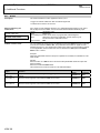
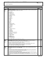
11. Used Parameters
D.. Reference Value
Par.
Description
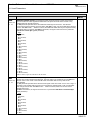
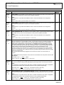
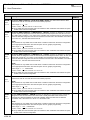
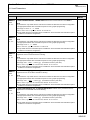
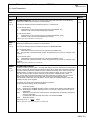
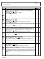
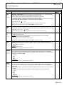
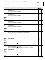
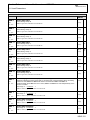
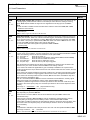
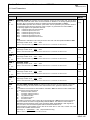
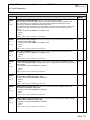
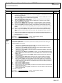
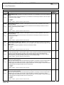
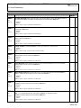
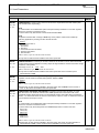
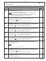
D34
Axis
r=2, w=2
Fieldbusaddress
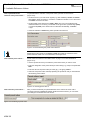
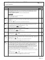
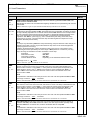
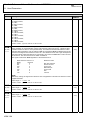
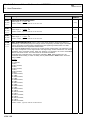
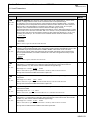
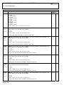
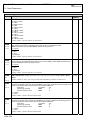
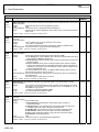
PID ref value source: D34 specifies the source for the PID reference value. The source can be
an analog signal, preset reference values or motorized pot value. When the setting is 0:analog
signals, G132 defines whether the signal is to be supplied via an analog input or via fieldbus.
2622h
0h
2623h
0h
2628h
0h
2629h
0h
NOTE
The PID controller is enabled if it was activated as the reference value PID in D30, D31 or D33.
0: Reference value external;
1: preset value;
2: motorised pot;
Fieldbus: 1LSB=1; Type: U8; USS-Adr: 04 08 80 00 hex
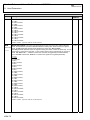
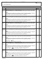
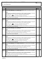
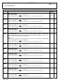
D35
Axis
r=2, w=2
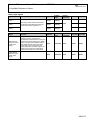
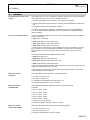
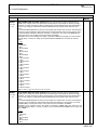
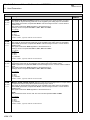
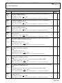
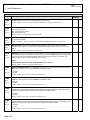
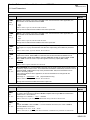
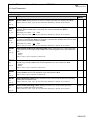
Mode limit switch: The comfort reference value application permits the positioning range to be
limited by limit switches. When one of the limit switches triggers, deceleration is performed with the
stop or quick stop ramp. The selection is made in D35. When the setting is 0:quickstop ramp, D85
is used. When 1:stop ramp is parameterized, D84 takes effect if the value of D84 is not zero. If this
is not the case, D85 quick stop ramp is also used for this setting.
The sources of the limit switch signals are specified in D103 and D104.
0: quickstop ramp;
1: stop ramp;
Fieldbus: 1LSB=1; Type: B; USS-Adr: 04 08 C0 00 hex
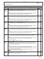
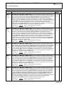
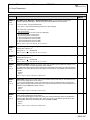
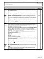
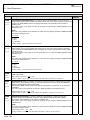
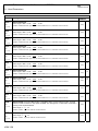
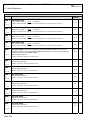
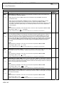
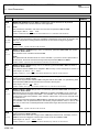
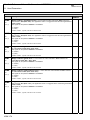
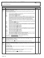
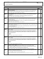
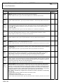
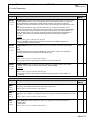
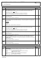
D40
Axis
r=2, w=2
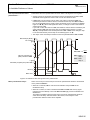
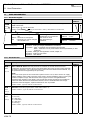
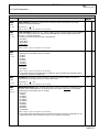
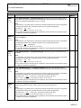
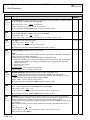
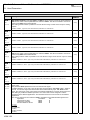
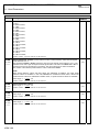
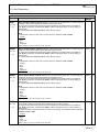
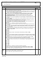
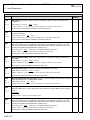
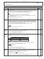
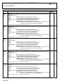
Motorised pot preset mode: The motorized pot reference value can be set to the value in D44
by using one or more conditions. A binary signal whose source can be selected in D116 is available
for this. The following choices can also be activated in the bit pattern D40:
Bit 0 - For power on:
Bit is set for power on.
Bit 1 - For stop:
Bit is set when a stop signal is active (selector D102, indication D302).
Bit 2 - For enable off:
Bit is set when the enable is turned off.
Bit 3 - For malfunction:
Bit is set when a malfunction occurs.
Bit 4 - For quick stop:
Bit is set when a quick stop is triggered.
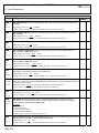
When several bits are selected and the binary signal in D116, the selections are OR-linked. This
means that only one of the conditions must be fulfilled for the setting of the bit.
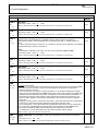
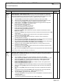
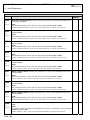
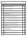
Bit 5 is used to set whether the applicable key (UP or DOWN) is disabled in the "speed control"
operating mode when the torque limits E180 or E181 are reached. When the bit is inactive, the keys
are not disabled.
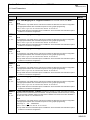
Bit 6 is used to set whether evaluation of the reset conditions is to be edge or level-triggered. When
the bit is inactive, evaluation is edge-triggered. When the bit is active, the signal level is evaluated.
Bit 7 is used to set the ramps. When the bit is inactive, D41 is used as the acceleration ramp and
D42 is used as the deceleration ramp.
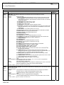
When bit 7 is activated, D41 and D42 are used for acceleration and deceleration. A binary signal
(setting of the signal source in D117) is used to switch between D41 and D42.
This makes it possible to approach the motorized pot reference value area with a fast ramp. After
the switch to the second (lower) ramp, the motorized pot reference value can be adjusted for more
sensitivity.
Value range: 0 ... 00000000bin ... 255
(Representation binary)
Fieldbus: 1LSB=1; Type: U8; USS-Adr: 04 0A 00 00 hex
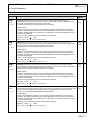
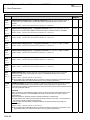
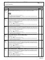
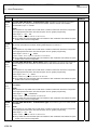
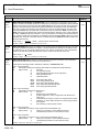
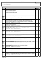
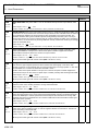
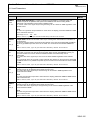
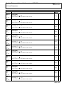
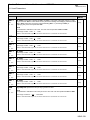
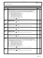
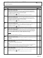
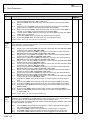
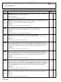
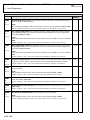
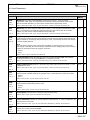
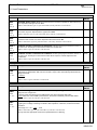
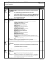
D41
Axis
r=1, w=2
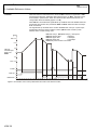
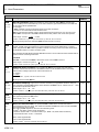
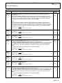
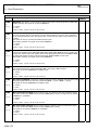
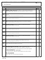
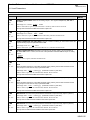
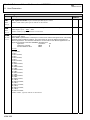
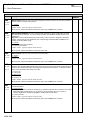
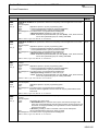
Motorised pot ramp 1: The ramps of the motorized pot reference value can be used in two
ways, depending on parameter D40 bit7:
• When the bit is 0:inactive, D41 is used as the acceleration ramp and D42 is used as the
deceleration ramp
• When the bit is activated, D41 and D42 are used for acceleration and deceleration. A binary
signal (setting of the signal source in D117) is used to switch between D41 and D42.
This makes it possible to approach the motorized pot reference value area with a fast ramp. After
the switch to the second (lower) ramp, the motorized pot reference value can be adjusted for
more sensitivity.
NOTE
This parameter is indicated in user units per second. The user units are specified in D87 and D88.
Value range in D249: 0 ... 100 ... 131072000
Fieldbus: 1LSB=siehe D86; Type: I32; raw value:1LSB=Fnct.no.18; USS-Adr: 04 0A 40 00 hex
KSW-141