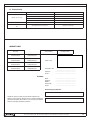
1
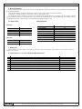
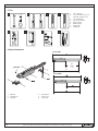
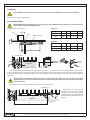
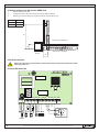
Installation and Operating Manual Operator SWING-3000/5000 Contents 2. General information................................................................................................................3 2.1 Extent of use..................................................................................................................3 2.2 Specifications.................................................................................................................3 3. Delivery set.............................................................................................................................3 4. Safety instructions..................................................................................................................4 5. Tools.......................................................................................................................................6 6. Operator components.............................................................................................................6 7. Installation..............................................................................................................................7 7.1 Inward gate opening.......................................................................................................7 7.2 outward gate opening via operator sWIng-5000............................................................8 8. Electrical connections.............................................................................................................8 8.1 Control unit connection..................................................................................................8 8.2 Control unit description..................................................................................................9 9. Programming..........................................................................................................................10 9.1 Radio control encoding..................................................................................................11 10. Extreme positions adjustment..............................................................................................11 10.1 Preparation...................................................................................................................11 10.2 Open position...............................................................................................................11 10.3 Closed position............................................................................................................12 11. Release operation.................................................................................................................12 12. Maintenance.........................................................................................................................12 13. Troubleshooting....................................................................................................................13 14. Guaranty card.......................................................................................................................13 2 I n s t a l l a t i o n a n d O p e r a t i n g M a n u a l O p e r a t o r S W I NG - 3 0 0 0 / 5 0 0 0 General Information 2. General Information The electromechanical linear operator produced by the company DoorHan is intended for automation of a street double-leaf swinging gate with the load-bearing structure. The body of the operator consists of 2 silumin parts, in which a motor, a reducer and a lead screw are positioned. The operator is equipped with built-in electrical end switches for opening and closing. The self-blocking system, consisting of a worm gear and a planetary gearbox blocks gate leaves, if the motor is off. The easy-to-use and safe release system allows to open/close manually the leaf, in case of power cut or any troubles in the control unit. Operation of the automatic system is controlled from the remote control unit, which is protected with a shockproof and hermetic case. 2.1 Range of Use Swing-5000 Leaf width 2.00 2.50 3.00 4.00 5.00 m Leaf weight 1000 800 600 500 400 kg m Leaf weight 800 600 400 kg Swing-3000 Leaf width 2.00 2.50 3.00 2.2 Specifications Weight Supply voltage Current consumption Capacity Intensity Ingress protection rating Gear ratio Rod speed Force Temperature range Capacitor Swing-5000 – 11 kg, Swing-3000 – 10 kg 220V, 50Hz 1.2A 150W 50% IP54 1/36 1.5cm/sec 3000N -40…+55C 10mf 3. Delivery Set After receiving the operator, unpack it and make sure, that the operator is not damaged. If any damages are found, please contact the supplier of the operator. A standard components set of operator SW-5000KIT/SW-3000KIT includes: № 1 2 3 4 5 6 7 8 9 3 Name Operator Rear fastening bracket Front fastening bracket Set of fasteners Control unit with case Key-switch Signal lamp Photo cells User manual I n s t a l l a t i o n a n d O p e r a t i n g M a n u a l O p e r a t o r S W I NG - 3 0 0 0 / 5 0 0 0 Quantity 2 2 2 1 1 1 1 1 1 3 Safety instructions 4. Safety instructions For safe operation of the automated gate, do observe these installation instructions. • Incorrect installation can cause serious damage to persons and property. • Before installation read carefully this manual. • Do not make any modifications in the automated system, which are not mentioned in this manual. • The operator SWING is intended for automation of swinging gates. Do not install the operator for uses other than indicated in this manual. • To fasten the product, use the supplied hardware or other suitable. • Check if the gate conforms to the standards EN12604 and EN 12605 (see documentation accompanying the gate). For countries, which are not EC members, the above mentioned requirements shall be met in order to obtain an appropriate safety level. • Make sure, that the gate is correctly operational and equipped with mechanical end limits. • Check periodically for tear and wear indications the installation, particularly, cables. • Do not use the operator if it is observed to function improperly or requires adjustment, as installation defects or non-balanced door can cause injury. • The operator is not appropriate for the usage with doors, which opening diameter exceeds 10mm or which have an edge or a protruding part, that can be seized or stopped by a person. When installing it is strictly recommended to observe the following: • Obtain the tools indicated in section “Tools” of this manual. • When performing operations at a height, use a stable support. • Protect your face and hands adequately when making holes with a drill. • Do not let children play near the moving gate. • Remove any restrictions’ in the coverage area of the automatic system before its start. • Before automatic opening the gate, make certain, that the mechanical lock is open. • Install the external control devices at a height not less than 1.50 m where visible and far enough from the automatic system, so that the user is prevented from coming into contact with the gate while operating the controls. • The operator is not intended for installation at a height exceeding 2.5 m. After you have finished installing: • Use the automatic system SWING, observing operating instructions. • Fill in regularly maintenance register. • A warning label must be fixed permanently on protruding parts or near the stationary control. • A permanent fixed label, related to the manual release, must be placed near the proper elements of the operator. • The automatic system SWING is maintenance-free. IMPORTANT! DANGER. If the supply cable is damaged, a cable of proper type shall be used as a replacement. Cable replacement is to be carried out by qualified personnel in the service-centre. ATTENTION: Important safety instruction. To avoid injury, follow the instructions contained in this manual. Save this manual. Materials and accessories (if available) for installation of the operator SWING: • Cable 2x0.5 mm2 (photocell transmitter, stepped control button) • Cable 4x0.5 mm2 (photocell receiver) • Cable 3x1.5 mm2 (supply) • Use the cables with proper voltage insulation. Have a qualified technician lay the cables 230V AC. Cabling shall be protected by protective flutes, avoid contact of the cables with moving parts of the gate. 4 I n s t a l l a t i o n a n d O p e r a t i n g M a n u a l O p e r a t o r S W I NG - 3 0 0 0 / 5 0 0 0 SAFETY AT INSTALLATION SAFETY AT INSTALLATION 1. 2. 3. 4. 5. 6. 7. 8. 9. 10. 11. 12. 13. 14. 15. 16. 17. 18. 19. 20. 21. 22. 23. 24. 25. 5 ATTENTION! Read carefully these instructions, incorrect installation and improper use of the operator can cause injury of people. Before installation read carefully this manual. Remove the packing of this product and dispose of it. Do not leave the packing material within reach of children. Save this manual for possible maintenance during the operational life of the operator. This product was designed for automation of swinging gates, other uses can cause injury to people. DOORHAN shall not be held responsible in case of injury or other health impairment caused by unintended use of the operator. Do not install the equipment in premises with quick-inflammables materials or in other dangerous environments, because it can cause explosion or fire. Mechanical units of the gate shall be constructed and installed in accordance with the standards EN12604 and EN 12605. DOORHAN is not responsible in case of incorrect installation of the product and if it is damaged during operation. The installation must be performed in accordance with the standards EN12453 and EN 12445. For countries, which are not EC members, these requirements are to be met. Before carrying out the works, de-energize the system. The automatic system shall be connected to the mains supply through an automatic switch. At that the distance between the contacts shall not be less than 3 mm. It is recommended to use the automat 6A. The safety devices of the operator protect against hazard of pinch through the gate while opening. DOORHAN is not responsible for unstable work of the automatic system, if the safety devices and accessories, which were produced by other manufacturers and without agreement with DOORHAN, are used. Use the accessories of the company DOORHAN, as the accessories of other manufactures can cause failure of the system. For maintenance, use only DOORHAN original parts. Do not make modification in the components of the automatic system. Be sure, that the installer has instructed you how to release the gate in case of emergency and on the proper operation and maintenance of the automatic system. Do not let any people to be in the operation area of the automatic system when it is working. Never let children play and be in the operation area of the automatic system, under the gate and near the gate, when the gate is moving and the operator is running. Passage is allowed only after the gate has been stopped and the operator is switched off. Have only qualified personnel, which was trained in the authorized centre DOORHAN, carry out repairs. Check good working condition of the safety sensors monthly. Maintenance: make diagnostics of the system SWING at least once a half-year, pay special attention to the gate travel smoothness in the released state and to good working condition of the release. It is forbidden to perform operations, which are not permitted by this manual. I n s t a l l a t i o n a n d O p e r a t i n g M a n u a l O p e r a t o r S W I NG - 3 0 0 0 / 5 0 0 0 5 Tools 5. Tools 1 2 3 1. 2. 4 3. 4. 5. 6. 7. 8. 5 6 7 Set of spanners Set of screwdrivers for crosshead and cut-head screws Set of metal drills Set of concrete drills Flat-nose pliers Metal hacksaw Electric drill Folding rule 8 6. Operator Components Swing 3000 793 300 Stroke Nut M8 720 Swing 5000 Stroke 1. 2. 3. 6 Operator Front bracket Rear fork 4. 5. 6. Rear bracket Release unit Lead screw I n s t a l l a t i o n a n d O p e r a t i n g M a n u a l O p e r a t o r S W I NG - 3 0 0 0 / 5 0 0 0 Installation 7. Installation Before installation make sure, that the gate move free and it is possible to fasten reliably the operator on the pole and the leaf. Installation of the operator is shown below: 7.1 Inward Gate Opening Attention! Make certain, that the dimension C does not exceeds the value indicated in the table. Otherwise it is necessary to improve the pole according to the indicated dimension value. Install the operator as shown below: Swing-3000 Pole Hinge Opening angle A, mm B, mm Cмакс, mm D, mm 90 130 130 60 720 1200 130 110 50 720 Opening angle A, mm B, mm Cмакс, mm D, mm 0 90 200 200 120 920 120 200 140 70 920 0 Gate leaf (closed) Swing-5000 0 mounting plate mounting plate Moving end part rear bracket Moving end part rear bracket 1) Fasten the rear bracket with the appropriate fastening plate on the pole so, as shown in the picture, observing dimensions A and B, namely, the distance between the axis of the bracket’s central hole and of the gate hinge shank. The rear bracket has several holes, which makes installation of the operator easier and allow changing opening angle of the gate. Depending on the position of the gate hinges you can lengthen or shorten the rear bracket. Attention! Increase of the dimension B results in decrease of the gate opening angle, angle speed of the leaf and in increase of the operator’s linear force. Increase of the dimension B results in increase of the gate opening angle, angle speed of the leaf and the operator’s linear force. 2) Install the steel end piece and lubricate the whole installation using neutral grease. mounting plate mounting plate building level When the gate is closed, install the mounting plate on the gate leaf. Make sure, that the front bracket is positioned horizontally on the same level with the rear bracket and that the dimension E has been observed. front bracket building level front bracket 7 I n s t a l l a t i o n a n d O p e r a t i n g M a n u a l O p e r a t o r S W I NG - 3 0 0 0 / 5 0 0 0 7 Outward opening of gate with operator SWING-5000 7.2 Outward opening of gate with operator SWING-5000 1) Measure dimensions A and B 2) Install and fasten the rear bracket on the pole using an additional bracket. 3)Open the gate, measure distance E and fasten the front bracket on the gate leaf. 130 B 130 Е 720 E А B External side of the object Internal side of the object Additional bracket A 8. Electrical Connections Wires in the cable shall be protected from the contact with any rough and sharp parts. All connections shall be made only if power is off. 8.1 Control Unit Connection radio receiver + - F Tr COM OP CL COM OP CL LAMP S-B-S RE N L FOTO PED OP CL COM STOP +24V S.Lock phase neutral C1 C2 signal lamp 1 2 3 4 5 6 7 8 9 10 11 12 13 14 15 16 17 18 19 20 21 NC COM COM NO NC + 2 photocells 3 - 2 4 + 3 5 220Â 220 540Ãö 540 8 I n s t a l l a t i o n a n d O p e r a t i n g M a n u a l O p e r a t o r S W I NG - 3 0 0 0 / 5 0 0 0 Control Unit Description 8.2 Control Unit Description Basic programming To go into the basic programming mode, press the key F. On the left display you will see name of the function, which is to be programmed and on the right display you will see current value of this function. The value can be changed by pressing keys + or -. If you press the key F again, you will see on the display the name of the next function and you will be able to program this and so on. After you have programmed all the functions you can exit the programming mode by pressing the key F. Motor run time programming In order to program time of motor run, you should install the leaves in closed position and couple the operators. Then enter the basic programming mode, select the function F and press +. The leaves will begin to open, after the leaves have been opened, you should give a control command. After that the leaves will close and programming is completed. Connection Terminal: 9 S-B-S (Full opening) 10 11 PED (partial opening – pedestrian passage) 12 13 FOTO OP - opening safety devices 14 FOTO CL - closing safety devices 15 COM negative supply voltage 16 STOP - unconditional stop (NC contact) 17 18 +24 V supply 19 +24 V supply 20 SLock (electromechanical lock) 21 Power supply (terminal marking on the card: PE-N-L): PE – connection to earth N: Power supply (neutral) L: power supply (phase) Connection of electric operators and signal lamp 1-2-3 M1: (terminals COM/OO/CL): for connection of the first electric operator. Can be used to open one leaf (in case of motorized wicket or motorized single-leaf gate). 4-5-6 M2: (terminals COM/OO/CL): for connection of the second electric operator. Can not be used to open one leaf. 7-8 LAMP: output for connection of cignal lamp (230V~40W max). Connector for accessories 9-10. S-B-S – command “Full Opening”:after closing the contacts of the device, which is connected to these terminals, the control unit will actuate full opening or closing of 2 leaves of the gate. In order to connect several devices, you should connect NO contacts of these devices parallel. 11-12. PED – command “Pedestrian passage” or “Close”: after closing the contacts of the device, which is connected to these terminals, the control unit will actuate stepped opening or closing the first leaf of the gate. In order to connect several devices, you should connect NO contacts of these devices parallel. 13-15. OP FOTO – Contacts for connection of opening safety devices (NC): these connections are used to avoid restrictions in the automatic system operation area during opening the gate leaves. Response of the devices during operating the gate causes reverse movement of the gate leaves or immediate stop and follow-up movement continuation. Response of the devices connected to these terminals, does not effect operation of the gate during closing. Note: If these terminals are not used, install a jumper between contacts 13-15. 9 I n s t a l l a t i o n a n d O p e r a t i n g M a n u a l O p e r a t o r S W I NG - 3 0 0 0 / 5 0 0 0 9 OPERATOR PROGRAMMING 14-15. CL FOTO – Contacts for connection of closing safety device (NC): these connections are used for protection from pinching people, animals and other objects in the gate aperture when leaves are closing. Response of the devices during operating the gate causes reverse movement of the gate leaves or immediate stop and follow-up reverse movement, if it is adjusted. Response of the devices, connected to these terminals does not effect operation of the automatic system during opening. If the gate is open and the sensors have responded, which are connected to these terminals, it will prevent any movement of the gate. Note: If these terminals are not used, install a jumper between contacts 14-15. 16-17. STOP – Contacts for connection of safety devices with NC contacts: after closing the contacts of a device, which is connected to this terminal, the control unit will stop the movement. In order to connect several devices, you should connect NC contacts of these devices in series. Note: If these terminals are not used, install a jumper between contacts STOP. 18. +24V= Plus for accessory power supply 19. +24V= Plus for accessory power supply Attention: maximal possible current from these terminals must not exceed 500mA. Calculate carefully the summed current, consumed by your devices. SLOCK – electromechanical lock supply voltage output If required, connect 12V electromechanical lock between the terminals 20 and 21. 9. Programming ADVANCED PROGRAMMING F - + Display Function A Setting of pause time before automatic closing 1-10 sec 2-20 sec 3-30 sec 4-60 sec 5-90 sec 6-120 sec 7-180 sec 8-360 sec 9-420 sec Display Function On default Н Maximal force at starting time: Y – function is on n – function is off n J Electromechanical lock Y – function is on n – function is off n L Pre-activation of signal lamp (5 sec): Y – function is on n – function is off n 0 0 b Setting of 1st motor force: B1 - minimal force B9 – maximal force C Force on 2nd leaf: Setting of 2nd motor force C1 – minimal force C9 – maximal force 9 П d 1st leaf closing delay: 1-1sec 2-5 sec 3-10 sec 4-15 sec 5-20 sec 6-25 sec 7-30 sec 8-36 sec 9-40 sec Indicator light: Light at opening and pause, flashing at closing, off in closed state 1-10 sec 2-20 sec 3-30 sec 4-60 sec 5-90 sec 6-120 sec 7-180 sec 8-360 sec 9-420 sec 0 О Safety device: Y- immediate reverse n – reverse after cleaning aperture n 1st leaf opening delay: 1-1sec 2-5 sec 3-10 sec 4-15 sec 5-20 sec 2 P If this function is on and automatic closing pause is set, it will close immediately after response of photocells Y – function is on n – function is off n S If this function is on If the gate is opening, the stop is possible only by the end switches, if the gate is closing – as usual Y – function is on n – function is off n II If this function is on Opening\closing only by holding the buttons Y- function is on n- function is off n У If this function is on the stop is possible only by the end switches Y – function is on n – function is off n E F 10 On default 9 Programming of motor run time I n s t a l l a t i o n a n d O p e r a t i n g M a n u a l O p e r a t o r S W I NG - 3 0 0 0 / 5 0 0 0 Advanced Programming Advanced Programming In order to go into ADVANCED PROGRAMMING mode, press the key F and holding it down, press the key +. You will see the name of the function to be programmed. On the right display you will see the current value of the function, which can be changed by pressing the keys + or -. If you press the key F repeatedly, you will se on the display the name of the next function and you will be able to program it. After all the functions have been programmed, pressing the key F will allow exiting the programming mode. 9.1 Radio Control Encoding To encode a remote control unit, press the key Tr on the control unit and release. You will see 2 blinking figures: 00 on the display. After that you should press the key on the remote control. You will see amount of saved remote controls on the display. To encode other remote controls repeat the above said procedure. Maximal amount of remote controls is 60. To delete remote controls, press the key Tr and hold it down for 10 sec, after that you will hear a click and you will see two figures: 00. That means that the remote controls have been deleted successfully. 10. Extreme Positions Adjustment 10.1 Preparation Screw casing Unscrew 2 tapping screws and remove casing of the screw Cover Unscrew 2 tapping screws and remove the cover Nut M8 Lead screw Install on the operator the front and back brackets 10.2 Open Position: 1. 2. 3. 4. Release the operator and put the gate leaf in fully open position. Unscrew fastening of the opening end switch. Move the end switch along the guide, until the microswitch contacts with the slide. Fix the microswitch. Microswitch of closing slowdown mode Lead screw End switch guide Cable holder End switch slide Opening end switch Bronze bushing 11 I n s t a l l a t i o n a n d O p e r a t i n g M aView nu A a l O p e r a t o r S W I NG - 3 0 0 0 / 5 0 0 0 11 Microswitch response area Closed Position 10.3 Closed Position: 1. 2. 3. 4. 5. View A Put the gate leaf in fully closed position, which can be determined by the mechanical stop. Unscrew fastening of the closing microswitch. Move the end microswitch along the guide until the microswitch contacts with the slide. Move the microswitch ahead until the microswitch finger leaves response area. Fix the microswitch. Microswitch response area Microswitch finger When adjusted final position, make sure that the limit switches working correctly: When you press the microswitch the gate movement should be stopped. 11. Release Operation 1. 2. 3. 4. Lift the cover. Insert the key and turn it by 1800 Open or close the gate by hand. To link the operator, turn the key by 1800 again. Attention! Before releasing (linking) the operator, disconnect power supply Key 1800 Cover 12. Maintenance • • • • Make sure, that the gate is operable and move evenly. Check good working condition of the system units and safety devices at least once every 6 month. Maintenance of the operator must be carried out by qualified specialists. Keep the operator clean. The manufacturing plant reserves the right to make changes in the products described in this manual without notice and without obligation to notify any persons of any such revisions or changes. The manual describes installation and adjustment operations of the operator SWING-5000\SWING-3000. Following the recommendations on operation and maintenance of the operator as well as recommendations on installation of the operator and the gate, described in this manual, will ensure long life of the equipment and will reduce the risk of accidents during installation and operation of the gate. Do observe safety rules during installation, operation and maintenance. If you have lost this manual, you can request for the duplicate to the following address: Russia, 143002, Moscovskaya oblast, Odintsovskiy r-n, s. Akulovo, ul.Novaya, 120. The manufacturer (DoorHan) does not handle installation, maintenance and operation of gates and gate automation and is not responsible for safety of installation, operation and maintenance of gates and gate automation. The content of this manual shall not be basis for any claim. 12 I n s t a l l a t i o n a n d O p e r a t i n g M a n u a l O p e r a t o r S W I NG - 3 0 0 0 / 5 0 0 0 TROUBLESHOOTING 13. Troubleshooting Symptom Operator does not run Possible reason Solution Power is off. Make sure, that the power is on. Obstruction at gate’s movement Remove the obstruction. Bad wiring connection Check reliability of electric wiring connection. Operator is released Engage the operator. Operator stops suddenly. Thermal protection is active. Let the operator cool. The gate does not open or close in full. Wrong adjustment of end switches. Adjust the end switches. GUARANTY CARD Serial number Bar-code Component part Component part Component part Component part Component part Component part Component part Component part Installation date Seller’s step Installation crew City/town Tel/fax ......................................................... ......................................................... ......................................................... ......................................................... Name City/town Address Postal code Tel/fax ......................................................... ......................................................... ......................................................... ......................................................... ......................................................... Customer Guaranteeing party signature Hereby we inform you that your data will be entered in the database of the company DoorHan and you will be notified with guarantee registration letter. We also can send your promotional materials and other explanatory materials. 13 Customer signature I n s t a l l a t i o n a n d O p e r a t i n g M a n u a l O p e r a t o r S W I NG - 3 0 0 0 / 5 0 0 0 13 Notes 14 I n s t a l l a t i o n a n d O p e r a t i n g M a n u a l O p e r a t o r S W I NG - 3 0 0 0 / 5 0 0 0 NOTES 15 I n s t a l l a t i o n a n d O p e r a t i n g M a n u a l O p e r a t o r S W I NG - 3 0 0 0 / 5 0 0 0 15 The company DoorHan thanks you for buying our products. We hope you will be satisfied with the quality of our product. If you need any further information about purchasing, distribution and maintenance, contact our regional agents or refer to our central office to the following address: Russia, 143002, Moscovskaya oblast, Odintsovskiy r-n, s. Akulovo, ul.Novaya, 120. Tel: +7(495)933-2400, 981-1133 E-mail: [email protected] www.doorhan.com