1
AX2200S / AX1250S / AX1240S Software Manual
Configuration Command Reference
For Version 2.4
AX1240S-S003X-60
Relevant products
This manual applies to the AX2200S, AX1250S, and AX1240S models of switches, and describes the functionality
in software version 2.4 of the AX2200S, AX1250S, and AX1240S series switches that is supported by the OS-LT4,
OS-LT3, and OS-LT2 software and optional licenses.
Export restrictions
In the event that any or all ALAXALA products (including technologies, programs and services) described or
contained herein are controlled under any of applicable export control laws and regulations (including the Foreign
Exchange and Foreign Trade Law of Japan and United States export control laws and regulations), such products
shall not be exported without obtaining the required export licenses from the authorities concerned in accordance
with the above laws.
Trademarks
-
Ethernet is a registered trademark of Xerox Corporation.
Microsoft is either a registered trademark or trademark of Microsoft Corporation in the United States and other
countries.
Windows is a registered trademark of Microsoft Corporation in the United States and other countries.
RSA and RSA SecurID are trademarks or registered trademarks of RSA Security Inc. in the United States and
other countries.
Wake on LAN is a registered trademark of IBM Corporation.
MagicPacket is a registered trademark of Advanced Micro Devices, Inc.
Other company and product names in this document are trademarks or registered trademarks of their respective
owners.
Reading and storing this manual
Before you use the equipment, carefully read the manual and make sure that you understand all safety precautions.
After reading the manual, keep it in a convenient place for easy reference.
Notes
Information in this document is subject to change without notice.
Editions history
July 2012 (Edition 7) AX1240S-S003X-60
Copyright
All Rights Reserved, Copyright(C),2008, 2012, ALAXALA Networks, Corp.
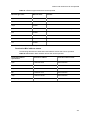
History of Amendments
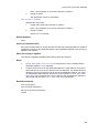
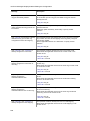
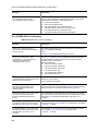
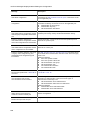
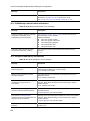
Ver. 2.4 (Edition 7)
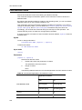
Table Summary of amendments
Location and title
Changes
Addition of series
A description of the AX2200S was added.
8. Ethernet
The following command was added.
power inline system-allocation
In addition to the above changes, minor editorial corrections were made.
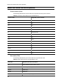
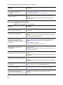
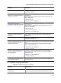
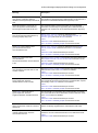
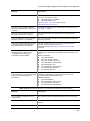
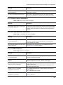
Ver. 2.3 (Edition 6)
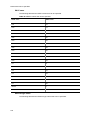
Table Summary of amendments
Location and title
Changes
Login Security and RADIUS
The explanation of the following command was changed.
ip access-group
Location and title
Changes
Ring Protocol
The following commands were added.
multi-fault-detection mode
multi-fault-detection vlan
Access Lists
The explanations of the following commands were changed.
deny (ip access-list extended)
ip access-group
mac access-group
permit (ip access-list extended)
QoS
The explanations of the following commands were changed.
ip qos-flow-group
mac qos-flow-group
Error messages displayed when
editing the configuration
The error messages for the following information were changed.
Ring Protocol information
CFM information
In addition to the above changes, minor editorial corrections were made.
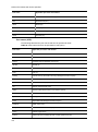
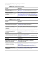
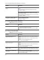
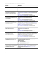
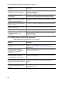
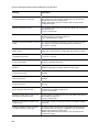
Ver. 2.3 (Edition 5)
Table Summary of amendments
Location and title
Changes
Login Security and RADIUS
The following commands was added.
aaa authentication login end-by-reject
Device Management
The following commands was added.
system fan mode
system temperature-warning-level
system temperature-warning-level average
Ethernet
The explanations of the following commands were changed.
bandwidth
mdix auto
Notes on using the following commands were added.
link debounce
ip dhcp snooping limit rate
ip dhcp snooping trust
ip verify source
DHCP snooping
Notes on using the following commands were added.
ip arp inspection limit rate
ip dhcp snooping limit rate
ip dhcp snooping trust
ip verify source
Common to Layer 2 Authentication
Notes on using the following commands were added.
authentication arp-relay
Web Authentication
The following command was added.
aaa authentication web-authentication end-by-reject
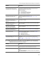
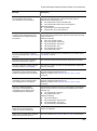
Location and title
Changes
MAC-based Authentication
The following commands was added.
aaa authentication mac-authentication end-by-reject
In addition to the above changes, minor editorial corrections were made.
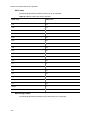
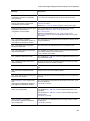
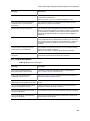
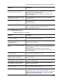
Ver. 2.2 (Edition 4)
Table Summary of amendments
Location and title
Changes
Addition of series
A description of AX1250S was added.
Reading the Manual
A description of AX1250S was added.
Device Management
The explanation of the following command was changed.
system recovery
Ethernet
Descriptions have been added with the support of the 100BASE-FX
(SFP).
duplex
flowcontrol
interface gigabitethernet
media-type
speed
Access Lists
Notes on using the following commands were added.
deny (mac access-list extended)
permit (mac access-list extended)
QoS
Note on using the following command was added.
qos (mac qos-flow-list)
Uplink redundancy
The following command was added.
switchport-backup startup-active-port-selection
In addition to the above changes, minor editorial corrections were made.
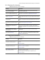
Ver. 2.2 (Edition 3)
Table Summary of amendments
Location and title
Changes
Reading the Manual
Login Security and RADIUS
The following commands were added.
aaa group server radius
radius-server attribute station-id capitalize
server
The parameter was added to the following command.
radius-server host
The list of the command modes was changed.
Location and title
Changes
Device Management
The following command was added.
system recovery
Power Saving Functionality
The timing when the settings of the following command are applied was
changed.
system fan-control
Ethernet
The following command was added.
linkscan-mode
VLAN
The explanation about the parameters of the following command was
changed.
switchport mode
Ring Protocol
This chapter was added.
IEEE802.1X
The following commands were added.
aaa accounting dot1x
dot1x authentication
Notes on the following commands were changed.
dot1x force-authorized
dot1x force-authorized vlan
dot1x vlan dynamic enable
dot1x vlan dynamic radius-vlan
The parameter was added to the following command.
dot1x radius-server host
The following command name was changed.
aaa authentication dot1x default to aaa
authentication dot1x
Web Authentication
The following commands were added.
aaa accounting web-authentication
web-authentication html-fileset
web-authentication authentication
web-authentication user-group
web-authentication user replacement
Notes on the following commands were changed.
web-authentication force-authorized vlan
web-authentication static-vlan force-authorized
web-authentication vlan
The parameter was added to the following command.
web-authentication radius-server host
The following command name was changed.
aaa authentication web-authentication default to aaa
authentication web-authentication
Location and title
Changes
MAC-based Authentication
The following commands were added.
aaa accounting mac-authentication
mac-authentication authentication
The parameter was added to the following command.
mac-authentication radius-server host
Notes on the following commands were changed.
mac-authentication interface
mac-authentication force-authorized vlan
mac-authentication vlan
mac-authentication static-vlan force-authorized
The following command name was changed.
aaa authentication web-authentication default to aaa
authentication web-authentication
Multistep authentication
The parameter was added to the following command.
authentication multi-step
CFM
This chapter was added.
SNMP
The parameter was added to the following command.
snmp-server host
Log Data Output Functionality
The following command was added.
logging syslog-header
Error messages displayed when
editing the configuration
The following information was added.
Information about the login security and RADIUS
Ring Protocol information
CFM information
The error messages for the following information were changed.
Information about the power saving functionality
Ethernet information
Link aggregation information
Spanning Tree information
IEEE 802.1X information
Web authentication information (including DHCP server information)
MAC-based authentication information
Uplink redundancy information
In addition to the above changes, minor editorial corrections were made.
Ver. 2.1 (Edition 2)
Table Summary of amendments
Location and title
Changes
Editing and Working with
Configurations
The response messages for the following commands were added.
end
exit
Location and title
Changes
Login Security and RADIUS
The explanations of the following commands were changed.
radius-server dead-interval
radius-server host
radius-server key
radius-server retransmit
radius-server timeout
Time Settings and NTP
Notes on the following commands were changed.
clock timezone
Power Saving Functionality
The following commands were added.
power-control port cool-standby
schedule-power-control port cool-standby
schedule-power-control port-led
schedule-power-control shutdown interface
schedule-power-control system-sleep
schedule-power-control time-range
system fan-control
system port-led trigger console
system port-led trigger interface
system port-led trigger mc
The explanation of the following command was changed.
system port-led
Ethernet
Notes on the following commands were changed.
shutdown
MAC Address Table
Notes on the following commands were changed.
mac-address-table aging-time
mac-address-table static
VLAN
Notes on the following commands were changed.
switchport mac
switchport mode
vlan
IGMP Snooping
The explanation of the following command was changed.
ip igmp snooping mrouter
MLD Snooping
The explanations of the following commands were changed.
ipv6 mld snooping source
ipv6 mld snooping mrouter
Common to Layer 2 Authentication
This chapter was moved.
The following commands were added.
authentication force-authorized enable
authentication force-authorized vlan
Location and title
Changes
IEEE802.1X
The following commands were added.
dot1x auto-logout
dot1x radius-server dead-interval
dot1x radius-server host
The parameter was added to the following command.
dot1x supplicant-detection
Notes on the following commands were changed.
dot1x force-authorized
dot1x force-authorized eapol
dot1x force-authorized vlan
dot1x port-control
dot1x vlan dynamic enable
dot1x vlan dynamic radius-vlan
Web Authentication
The following commands were added.
web-authentication radius-server dead-interval
web-authentication radius-server host
The parameter was added to the following command.
aaa authentication web-authentication default
Notes on the following commands were changed.
web-authentication force-authorized vlan
web-authentication static-vlan force-authorized
web-authentication vlan
MAC-based Authentication
The following commands were added.
mac-authentication radius-server dead-interval
mac-authentication radius-server host
The parameter was added to the following command.
aaa authentication mac-authentication default
Notes on the following commands were changed.
mac-authentication force-authorized vlan
mac-authentication interface
mac-authentication static-vlan force-authorized
mac-authentication timeout quiet-period
mac-authentication vlan
Multistep authentication
This chapter was added.
Secure Wake-on-LAN [OP-WOL]
Notes on the following commands were changed.
http-server
Uplink redundancy
The following commands were added.
switchport backup mac-address-table update transmit
switchport backup mac-address-table update exclude-vlan
switchport backup mac-address-table update retransmit
Storm Control
The parameter was added to the following command.
storm-control
Port Mirroring
Notes on the following commands were changed.
monitor session
Location and title
Changes
Error messages displayed when
editing the configuration
The following information was added.
Information about the power saving functionality
Multistep authentication information
Storm control information
The error messages for the following information were changed.
Link aggregation information
MAC address table information
VLAN information
IGMP snooping information
MLD snooping information
Layer 2 authentication common information
IEEE 802.1X information
Web authentication information (include DHCP server information)
MAC-based authentication information
Uplink redundancy information
Port mirroring information
In addition to the above changes, minor editorial corrections were made.
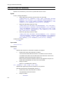
Preface
Applicable products and software versions
This manual applies to the AX2200S, AX1250S, and AX1240S models of switches, and
describes the functionality in software version 2.4 of the AX2200S, AX1250S, and
AX1240S series switches that is supported by the OS-LT4, OS-LT3, OS-LT3-A, OS-LT2,
and OS-LT2-A software and optional licenses.
Before you operate the equipment, carefully read the manual and make sure that you
understand all instructions and cautionary notes. After reading the manual, keep it in a
convenient place for easy reference.
Unless otherwise noted, this manual describes the functions applicable to the AX2200S,
AX1250S, and AX1240S. Model-specific functions are indicated as follows:
[AX2200S]:
The description applies to the AX2200S switch.
[AX1250S]:
The description applies to the AX1250S switch.
[AX1240S]:
The description applies to the AX1240S switch.
Unless otherwise noted, this manual describes the functions of the OS-LT4, OS-LT3, and
OS-LT2 base software. The functions of software supported by optional licenses are
indicated as follows:
[OP-WOL]:
The description applies to the OP-WOL optional license.
[OP-OTP]:
The description applies to the OP-OTP optional license.
Corrections to the manual
Corrections to this manual might be contained in the Release Notes and Manual
Corrections that come with the software.
Intended readers
This manual is intended for system administrators who wish to configure and operate a
network system that uses the Switch.
Readers must have an understanding of the following:
The basics of network system management
Manual URL
You can view this manual on our website at:
http://www.alaxala.com/en/
Reading sequence of the manuals
The following shows the manuals you need to consult according to your requirements
determined from the following workflow for installing, setting up, and starting regular
operation of the Switch.
I
Preface
Abbreviations used in the manual
AC
ACK
ADSL
ALG
ANSI
ARP
AS
AUX
BGP
BGP4
BGP4+
bit/s
BPDU
BRI
CC
II
Alternating Current
ACKnowledge
Asymmetric Digital Subscriber Line
Application Level Gateway
American National Standards Institute
Address Resolution Protocol
Autonomous System
Auxiliary
Border Gateway Protocol
Border Gateway Protocol - version 4
Multiprotocol Extensions for Border Gateway Protocol - version 4
bits per second
(can also appear as bps)
Bridge Protocol Data Unit
Basic Rate Interface
Continuity Check
Preface
CDP
CFM
CIDR
CIR
CIST
CLNP
CLNS
CONS
CRC
CSMA/CD
CSNP
CST
DA
DC
DCE
DHCP
DIS
DNS
DR
DSAP
DSCP
DTE
DVMRP
E-Mail
EAP
EAPOL
EFM
ES
FAN
FCS
FDB
FQDN
FTTH
GBIC
GSRP
HMAC
IANA
ICMP
ICMPv6
ID
IEC
IEEE
IETF
IGMP
IP
IPCP
IPv4
IPv6
IPV6CP
IPX
ISO
ISP
IST
L2LD
LAN
LCP
LED
LLC
LLDP
LLQ+3WFQ
LSP
LSP
LSR
Cisco Discovery Protocol
Connectivity Fault Management
Classless Inter-Domain Routing
Committed Information Rate
Common and Internal Spanning Tree
ConnectionLess Network Protocol
ConnectionLess Network System
Connection Oriented Network System
Cyclic Redundancy Check
Carrier Sense Multiple Access with Collision Detection
Complete Sequence Numbers PDU
Common Spanning Tree
Destination Address
Direct Current
Data Circuit terminating Equipment
Dynamic Host Configuration Protocol
Draft International Standard/Designated Intermediate System
Domain Name System
Designated Router
Destination Service Access Point
Differentiated Services Code Point
Data Terminal Equipment
Distance Vector Multicast Routing Protocol
Electronic Mail
Extensible Authentication Protocol
EAP Over LAN
Ethernet in the First Mile
End System
Fan Unit
Frame Check Sequence
Filtering DataBase
Fully Qualified Domain Name
Fiber To The Home
GigaBit Interface Converter
Gigabit Switch Redundancy Protocol
Keyed-Hashing for Message Authentication
Internet Assigned Numbers Authority
Internet Control Message Protocol
Internet Control Message Protocol version 6
Identifier
International Electrotechnical Commission
Institute of Electrical and Electronics Engineers, Inc.
the Internet Engineering Task Force
Internet Group Management Protocol
Internet Protocol
IP Control Protocol
Internet Protocol version 4
Internet Protocol version 6
IP Version 6 Control Protocol
Internetwork Packet Exchange
International Organization for Standardization
Internet Service Provider
Internal Spanning Tree
Layer 2 Loop Detection
Local Area Network
Link Control Protocol
Light Emitting Diode
Logical Link Control
Link Layer Discovery Protocol
Low Latency Queueing + 3 Weighted Fair Queueing
Label Switched Path
Link State PDU
Label Switched Router
III
Preface
MA
MAC
MC
MD5
MDI
MDI-X
MEP
MIB
MIP
MRU
MSTI
MSTP
MTU
NAK
NAS
NAT
NCP
NDP
NET
NLA ID
NPDU
NSAP
NSSA
NTP
OADP
OAM
OSPF
OUI
packet/s
PAD
PAE
PC
PCI
PDU
PICS
PID
PIM
PIM-DM
PIM-SM
PIM-SSM
PoE
PRI
PS
PSNP
QoS
RA
RADIUS
RDI
REJ
RFC
RIP
RIPng
RMON
RPF
RQ
RSTP
SA
SD
SDH
SDU
SEL
SFD
SFP
IV
Maintenance Association
Media Access Control
Memory Card
Message Digest 5
Medium Dependent Interface
Medium Dependent Interface crossover
Maintenance association End Point
Management Information Base
Maintenance domain Intermediate Point
Maximum Receive Unit
Multiple Spanning Tree Instance
Multiple Spanning Tree Protocol
Maximum Transfer Unit
Not AcKnowledge
Network Access Server
Network Address Translation
Network Control Protocol
Neighbor Discovery Protocol
Network Entity Title
Next-Level Aggregation Identifier
Network Protocol Data Unit
Network Service Access Point
Not So Stubby Area
Network Time Protocol
Octpower Auto Discovery Protocol
Operations,Administration,and Maintenance
Open Shortest Path First
Organizationally Unique Identifier
packets per second
(can also appear as pps)
PADding
Port Access Entity
Personal Computer
Protocol Control Information
Protocol Data Unit
Protocol Implementation Conformance Statement
Protocol IDentifier
Protocol Independent Multicast
Protocol Independent Multicast-Dense Mode
Protocol Independent Multicast-Sparse Mode
Protocol Independent Multicast-Source Specific Multicast
Power over Ethernet
Primary Rate Interface
Power Supply
Partial Sequence Numbers PDU
Quality of Service
Router Advertisement
Remote Authentication Dial In User Service
Remote Defect Indication
REJect
Request For Comments
Routing Information Protocol
Routing Information Protocol next generation
Remote Network Monitoring MIB
Reverse Path Forwarding
ReQuest
Rapid Spanning Tree Protocol
Source Address
Secure Digital
Synchronous Digital Hierarchy
Service Data Unit
NSAP SELector
Start Frame Delimiter
Small Form factor Pluggable
Preface
SMTP
SNAP
SNMP
SNP
SNPA
SPF
SSAP
STP
TA
TACACS+
TCP/IP
TLA ID
TLV
TOS
TPID
TTL
UDLD
UDP
ULR
UPC
UPC-RED
VAA
VLAN
VRRP
WAN
WDM
WFQ
WRED
WS
WWW
XFP
Simple Mail Transfer Protocol
Sub-Network Access Protocol
Simple Network Management Protocol
Sequence Numbers PDU
Subnetwork Point of Attachment
Shortest Path First
Source Service Access Point
Spanning Tree Protocol
Terminal Adapter
Terminal Access Controller Access Control System Plus
Transmission Control Protocol/Internet Protocol
Top-Level Aggregation Identifier
Type, Length, and Value
Type Of Service
Tag Protocol Identifier
Time To Live
Uni-Directional Link Detection
User Datagram Protocol
Uplink Redundant
Usage Parameter Control
Usage Parameter Control - Random Early Detection
VLAN Access Agent
Virtual LAN
Virtual Router Redundancy Protocol
Wide Area Network
Wavelength Division Multiplexing
Weighted Fair Queueing
Weighted Random Early Detection
Work Station
World-Wide Web
10 gigabit small Form factor Pluggable
Conventions: KB, MB, GB, and TB
This manual uses the following conventions: 1 KB (kilobyte) is 1024 bytes. 1 MB
2
3
4
(megabyte) is 1024 bytes. 1 GB (gigabyte) is 1024 bytes. 1 TB (terabyte) is 1024 bytes.
Conventions: The terms "Switch" and "switch"
The term Switch (upper-case "S") is an abbreviation for any or all of the following models:
AX2200S series switch
AX1250S series switch
AX1240S series switch
The term switch (lower-case "s") might refer to a Switch, another type of switch from the
current vendor, or a switch from another vendor. The context decides the meaning.
V
Preface
VI
Contents
Preface .............................................................................................................................................. I
Part 1: Reading the Manual ............................................................................................................ 1
1. Reading the Manual .................................................................................................................... 1
Command description format .................................................................................................. 2
Command mode list ................................................................................................................ 3
Specifiable values for parameters ........................................................................................... 4
List of character codes ............................................................................................................ 8
Part 2: Operation and Management of Switches .......................................................................... 9
2. Connecting from an Operation Terminal .................................................................................. 9
ftp-server ................................................................................................................................. 10
line vty ..................................................................................................................................... 11
transport input ......................................................................................................................... 12
3. Editing and Working with Configurations ................................................................................ 13
end ......................................................................................................................................... 14
exit ......................................................................................................................................... 15
save (write) .............................................................................................................................. 16
show ........................................................................................................................................ 17
top ......................................................................................................................................... 18
4. Login Security and RADIUS ....................................................................................................... 19
aaa group server radius .......................................................................................................... 20
aaa authentication login .......................................................................................................... 21
aaa authentication login end-by-reject .................................................................................... 23
ip access-group ....................................................................................................................... 24
radius-server attribute station-id capitalize .............................................................................. 26
radius-server dead-interval ..................................................................................................... 27
radius-server host.................................................................................................................... 29
radius-server key ..................................................................................................................... 32
radius-server retransmit .......................................................................................................... 33
radius-server timeout............................................................................................................... 34
server ...................................................................................................................................... 35
5. Time Settings and NTP ............................................................................................................... 37
clock timezone ......................................................................................................................... 38
ntp client server ....................................................................................................................... 40
ntp client broadcast ................................................................................................................. 41
ntp client multicast ................................................................................................................... 42
ntp interval ............................................................................................................................... 43
6. Device Management ................................................................................................................... 45
system fan mode ..................................................................................................................... 46
system function [AX1250S] [AX1240S] ................................................................................... 48
system l2-table mode .............................................................................................................. 49
system recovery ...................................................................................................................... 51
system temperature-warning-level .......................................................................................... 52
system temperature-warning-level average ............................................................................ 54
7. Power Saving Functionality ....................................................................................................... 57
power-control port cool-standby .............................................................................................. 58
schedule-power-control port cool-standby .............................................................................. 59
schedule-power-control port-led .............................................................................................. 60
schedule-power-control shutdown interface............................................................................ 62
i
Contents
schedule-power-control system-sleep [AX1250S] [AX1240S] ................................................ 64
schedule-power-control time-range ......................................................................................... 65
system fan-control [AX1240S]................................................................................................. 70
system port-led ........................................................................................................................ 72
system port-led trigger console ............................................................................................... 74
system port-led trigger interface.............................................................................................. 75
system port-led trigger mc ....................................................................................................... 76
Part 3: Network Interfaces .............................................................................................................. 77
8. Ethernet ....................................................................................................................................... 77
bandwidth ................................................................................................................................ 78
description ............................................................................................................................... 79
duplex ...................................................................................................................................... 80
flowcontrol ............................................................................................................................... 82
interface fastethernet [AX1250S] [AX1240S] .......................................................................... 84
interface gigabitethernet .......................................................................................................... 85
link debounce .......................................................................................................................... 86
linkscan-mode [AX1250S] [AX1240S] .................................................................................... 87
mdix auto ................................................................................................................................. 88
media-type [AX1250S] [AX1240S] .......................................................................................... 89
mtu ......................................................................................................................................... 91
power inline [AX2200S] [AX1240S]......................................................................................... 93
power inline allocation [AX2200S] [AX1240S] ........................................................................ 95
power inline priority-control disable [AX2200S] [AX1240S] .................................................... 97
power inline system-allocation [AX2200S] .............................................................................. 98
shutdown ................................................................................................................................. 99
speed ....................................................................................................................................... 100
system mtu .............................................................................................................................. 102
9. Link Aggregation......................................................................................................................... 105
channel-group lacp system-priority ......................................................................................... 106
channel-group max-active-port ............................................................................................... 107
channel-group mode ............................................................................................................... 109
channel-group periodic-timer .................................................................................................. 111
description ............................................................................................................................... 112
interface port-channel.............................................................................................................. 113
lacp port-priority....................................................................................................................... 114
lacp system-priority ................................................................................................................. 116
shutdown ................................................................................................................................. 117
Part 4: Layer 2 Switching ................................................................................................................ 119
10. MAC Address Table .................................................................................................................. 119
mac-address-table aging-time ................................................................................................. 120
mac-address-table static ......................................................................................................... 121
11. VLANs ........................................................................................................................................ 123
interface vlan ........................................................................................................................... 124
l2protocol-tunnel eap ............................................................................................................... 125
l2protocol-tunnel stp ................................................................................................................ 126
mac-address ............................................................................................................................ 127
name........................................................................................................................................ 128
protocol .................................................................................................................................... 129
state ......................................................................................................................................... 130
switchport access .................................................................................................................... 131
switchport isolation .................................................................................................................. 132
switchport mac ........................................................................................................................ 134
switchport mode ...................................................................................................................... 137
switchport protocol .................................................................................................................. 139
ii
Contents
switchport trunk ....................................................................................................................... 141
vlan ......................................................................................................................................... 143
vlan-protocol ............................................................................................................................ 146
12. Spanning Tree Protocols ......................................................................................................... 149
instance ................................................................................................................................... 151
name........................................................................................................................................ 153
revision .................................................................................................................................... 154
spanning-tree bpdufilter........................................................................................................... 155
spanning-tree bpduguard ........................................................................................................ 156
spanning-tree cost ................................................................................................................... 157
spanning-tree disable .............................................................................................................. 159
spanning-tree guard ................................................................................................................ 160
spanning-tree link-type ............................................................................................................ 162
spanning-tree loopguard default ............................................................................................. 163
spanning-tree mode ................................................................................................................ 164
spanning-tree mst configuration .............................................................................................. 165
spanning-tree mst cost ............................................................................................................ 166
spanning-tree mst forward-time .............................................................................................. 167
spanning-tree mst hello-time ................................................................................................... 168
spanning-tree mst max-age..................................................................................................... 169
spanning-tree mst max-hops ................................................................................................... 170
spanning-tree mst port-priority ................................................................................................ 171
spanning-tree mst root priority ................................................................................................ 172
spanning-tree mst transmission-limit....................................................................................... 173
spanning-tree pathcost method ............................................................................................... 174
spanning-tree port-priority ....................................................................................................... 176
spanning-tree portfast ............................................................................................................. 177
spanning-tree portfast bpduguard default ............................................................................... 178
spanning-tree portfast default.................................................................................................. 179
spanning-tree single ................................................................................................................ 180
spanning-tree single cost ........................................................................................................ 181
spanning-tree single forward-time ........................................................................................... 182
spanning-tree single hello-time ............................................................................................... 183
spanning-tree single max-age ................................................................................................. 184
spanning-tree single mode ...................................................................................................... 185
spanning-tree single pathcost method .................................................................................... 186
spanning-tree single port-priority ............................................................................................. 188
spanning-tree single priority .................................................................................................... 189
spanning-tree single transmission-limit ................................................................................... 190
spanning-tree vlan ................................................................................................................... 191
spanning-tree vlan cost ........................................................................................................... 192
spanning-tree vlan forward-time .............................................................................................. 194
spanning-tree vlan hello-time .................................................................................................. 196
spanning-tree vlan max-age .................................................................................................... 197
spanning-tree vlan mode ......................................................................................................... 198
spanning-tree vlan pathcost method ....................................................................................... 199
spanning-tree vlan port-priority ............................................................................................... 201
spanning-tree vlan priority ....................................................................................................... 202
spanning-tree vlan transmission-limit ...................................................................................... 203
13. Ring Protocol ............................................................................................................................ 205
axrp ......................................................................................................................................... 206
axrp vlan-mapping ................................................................................................................... 207
axrp-ring-port ........................................................................................................................... 209
control-vlan .............................................................................................................................. 211
disable ..................................................................................................................................... 213
forwarding-shift-time ................................................................................................................ 214
iii
Contents
mode........................................................................................................................................ 215
multi-fault-detection mode ....................................................................................................... 216
multi-fault-detection vlan ......................................................................................................... 217
name........................................................................................................................................ 218
vlan-group ............................................................................................................................... 219
14. DHCP Snooping ........................................................................................................................ 221
ip arp inspection limit rate ....................................................................................................... 222
ip arp inspection trust .............................................................................................................. 223
ip arp inspection validate ......................................................................................................... 224
ip arp inspection vlan............................................................................................................... 226
ip dhcp snooping ..................................................................................................................... 228
ip dhcp snooping database url ................................................................................................ 229
ip dhcp snooping database write-delay ................................................................................... 231
ip dhcp snooping information option allow-untrusted .............................................................. 233
ip dhcp snooping limit rate ...................................................................................................... 234
ip dhcp snooping trust ............................................................................................................. 235
ip dhcp snooping verify mac-address...................................................................................... 236
ip dhcp snooping vlan.............................................................................................................. 237
ip source binding ..................................................................................................................... 238
ip verify source ........................................................................................................................ 240
15. IGMP Snooping ......................................................................................................................... 243
ip igmp snooping (global) ........................................................................................................ 244
ip igmp snooping (interface) .................................................................................................... 245
ip igmp snooping mrouter ........................................................................................................ 246
ip igmp snooping querier ......................................................................................................... 248
16. MLD Snooping .......................................................................................................................... 249
ipv6 mld snooping (global) ...................................................................................................... 250
ipv6 mld snooping (interface) .................................................................................................. 251
ipv6 mld snooping source ....................................................................................................... 252
ipv6 mld snooping mrouter ...................................................................................................... 253
ipv6 mld snooping querier ....................................................................................................... 255
Part 5: Forwarding IPv4 Packets .................................................................................................... 257
17. IPv4, ARP, and ICMP ................................................................................................................. 257
ip address ................................................................................................................................ 258
ip route .................................................................................................................................... 259
ip mtu ....................................................................................................................................... 261
Part 6: Common to Filtering and QoS ........................................................................................... 263
18. Flow Detection Mode................................................................................................................ 263
flow detection mode ................................................................................................................ 264
Part 7: Filters .................................................................................................................................... 267
19. Access Lists .............................................................................................................................. 267
Names that can be specified ................................................................................................... 268
deny (ip access-list extended) ................................................................................................. 274
deny (ip access-list standard) ................................................................................................. 280
deny (mac access-list extended) ............................................................................................. 282
ip access-group ....................................................................................................................... 285
ip access-list extended ............................................................................................................ 287
ip access-list resequence ........................................................................................................ 289
ip access-list standard ............................................................................................................. 291
mac access-group ................................................................................................................... 293
mac access-list extended ........................................................................................................ 295
mac access-list resequence .................................................................................................... 297
iv
Contents
permit (ip access-list extended) .............................................................................................. 299
permit (ip access-list standard) ............................................................................................... 305
permit (mac access-list extended) .......................................................................................... 307
remark ..................................................................................................................................... 310
Part 8: QoS ....................................................................................................................................... 311
20. QoS ............................................................................................................................................ 311
Names and values that can be specified ................................................................................ 312
ip qos-flow-group ..................................................................................................................... 318
ip qos-flow-list .......................................................................................................................... 320
ip qos-flow-list resequence ...................................................................................................... 321
limit-queue-length .................................................................................................................... 323
mac qos-flow-group ................................................................................................................. 325
mac qos-flow-list...................................................................................................................... 327
mac qos-flow-list resequence .................................................................................................. 328
qos (ip qos-flow-list) ................................................................................................................ 330
qos (mac qos-flow-list) ............................................................................................................ 336
qos-queue-group ..................................................................................................................... 340
qos-queue-list .......................................................................................................................... 341
remark ..................................................................................................................................... 344
traffic-shape rate ..................................................................................................................... 345
control-packet user-priority ...................................................................................................... 347
Part 9: Layer 2 Authentication........................................................................................................ 349
21. Common to Layer 2 Authentication ........................................................................................ 349
authentication arp-relay ........................................................................................................... 350
authentication force-authorized enable ................................................................................... 352
authentication force-authorized vlan ....................................................................................... 354
authentication ip access-group ............................................................................................... 355
22. IEEE802.1X ................................................................................................................................ 357
Correspondence between configuration commands and authentication modes .................... 358
aaa accounting dot1x .............................................................................................................. 361
aaa authentication dot1x ......................................................................................................... 362
aaa authorization network default ........................................................................................... 364
dot1x authentication ................................................................................................................ 365
dot1x auto-logout..................................................................................................................... 367
dot1x force-authorized............................................................................................................. 368
dot1x force-authorized eapol ................................................................................................... 370
dot1x force-authorized vlan ..................................................................................................... 371
dot1x ignore-eapol-start .......................................................................................................... 374
dot1x max-req ......................................................................................................................... 375
dot1x multiple-authentication .................................................................................................. 376
dot1x port-control .................................................................................................................... 378
dot1x radius-server dead-interval ............................................................................................ 380
dot1x radius-server host .......................................................................................................... 382
dot1x reauthentication ............................................................................................................. 385
dot1x supplicant-detection ...................................................................................................... 386
dot1x system-auth-control ....................................................................................................... 388
dot1x timeout keep-unauth ...................................................................................................... 389
dot1x timeout quiet-period ....................................................................................................... 391
dot1x timeout reauth-period .................................................................................................... 392
dot1x timeout server-timeout ................................................................................................... 394
dot1x timeout supp-timeout ..................................................................................................... 395
dot1x timeout tx-period ............................................................................................................ 396
dot1x vlan dynamic enable ...................................................................................................... 397
dot1x vlan dynamic ignore-eapol-start .................................................................................... 398
dot1x vlan dynamic max-req ................................................................................................... 399
v
Contents
dot1x vlan dynamic radius-vlan ............................................................................................... 400
dot1x vlan dynamic reauthentication ....................................................................................... 402
dot1x vlan dynamic supplicant-detection ................................................................................ 403
dot1x vlan dynamic timeout quiet-period................................................................................. 405
dot1x vlan dynamic timeout reauth-period .............................................................................. 406
dot1x vlan dynamic timeout server-timeout ............................................................................ 408
dot1x vlan dynamic timeout supp-timeout ............................................................................... 409
dot1x vlan dynamic timeout tx-period...................................................................................... 410
23. Web Authentication .................................................................................................................. 411
Correspondence between configuration commands and authentication modes .................... 413
aaa accounting web-authentication......................................................................................... 416
aaa authentication web-authentication.................................................................................... 417
aaa authentication web-authentication end-by-reject ............................................................. 419
web-authentication authentication ........................................................................................... 420
web-authentication auto-logout ............................................................................................... 422
web-authentication force-authorized vlan ............................................................................... 423
web-authentication html-fileset ................................................................................................ 426
web-authentication ip address ................................................................................................ 427
web-authentication jump-url .................................................................................................... 429
web-authentication logout ping tos-windows .......................................................................... 431
web-authentication logout ping ttl ............................................................................................ 432
web-authentication logout polling count .................................................................................. 433
web-authentication logout polling enable ................................................................................ 435
web-authentication logout polling interval ............................................................................... 437
web-authentication logout polling retry-interval ....................................................................... 439
web-authentication max-timer ................................................................................................. 441
web-authentication max-user .................................................................................................. 443
web-authentication max-user (interface) ................................................................................. 445
web-authentication port ........................................................................................................... 447
web-authentication radius-server dead-interval ...................................................................... 448
web-authentication radius-server host .................................................................................... 450
web-authentication redirect-mode ........................................................................................... 453
web-authentication redirect enable ......................................................................................... 454
web-authentication redirect tcp-port ........................................................................................ 455
web-authentication roaming .................................................................................................... 457
web-authentication static-vlan force-authorized ...................................................................... 459
web-authentication static-vlan max-user ................................................................................. 461
web-authentication static-vlan max-user (interface) ............................................................... 463
web-authentication static-vlan roaming ................................................................................... 465
web-authentication system-auth-control ................................................................................. 467
web-authentication user-group ................................................................................................ 468
web-authentication user replacement ..................................................................................... 470
web-authentication vlan .......................................................................................................... 471
web-authentication web-port ................................................................................................... 473
default-router ........................................................................................................................... 475
dns-server ............................................................................................................................... 476
ip dhcp excluded-address ....................................................................................................... 477
ip dhcp pool ............................................................................................................................. 478
lease ........................................................................................................................................ 479
max-lease ................................................................................................................................ 481
network .................................................................................................................................... 483
service dhcp ............................................................................................................................ 485
24. MAC-based Authentication ...................................................................................................... 487
Correspondence between configuration commands and authentication modes .................... 488
aaa accounting mac-authentication ........................................................................................ 490
aaa authentication mac-authentication ................................................................................... 491
vi
Contents
aaa authentication mac-authentication end-by-reject ............................................................. 493
mac-authentication access-group ........................................................................................... 494
mac-authentication authentication .......................................................................................... 495
mac-authentication auto-logout ............................................................................................... 497
mac-authentication force-authorized vlan ............................................................................... 499
mac-authentication id-format ................................................................................................... 502
mac-authentication interface ................................................................................................... 504
mac-authentication max-timer ................................................................................................. 506
mac-authentication max-user .................................................................................................. 507
mac-authentication max-user (interface)................................................................................. 509
mac-authentication password ................................................................................................. 511
mac-authentication port ........................................................................................................... 513
mac-authentication radius-server dead-interval ...................................................................... 514
mac-authentication radius-server host .................................................................................... 516
mac-authentication roaming .................................................................................................... 519
mac-authentication static-vlan force-authorized ..................................................................... 521
mac-authentication static-vlan max-user................................................................................. 523
mac-authentication static-vlan max-user (interface) ............................................................... 525
mac-authentication static-vlan roaming................................................................................... 527
mac-authentication system-auth-control ................................................................................. 529
mac-authentication timeout quiet-period ................................................................................. 530
mac-authentication timeout reauth-period .............................................................................. 532
mac-authentication vlan .......................................................................................................... 533
mac-authentication vlan-check ................................................................................................ 535
25. Multistep Authentication .......................................................................................................... 537
authentication multi-step ......................................................................................................... 538
26. Secure Wake-on-LAN [OP-WOL] ............................................................................................. 541
http-server [OP-WOL].............................................................................................................. 542
Part 10: High Reliability Based on Redundant Configurations .................................................. 545
27. Uplink Redundancy .................................................................................................................. 545
switchport backup interface ..................................................................................................... 546
switchport backup flush request transmit ................................................................................ 548
switchport backup mac-address-table update exclude-vlan ................................................... 549
switchport backup mac-address-table update retransmit ....................................................... 550
switchport backup mac-address-table update transmit........................................................... 551
switchport-backup startup-active-port-selection ...................................................................... 552
Part 11: High Reliability Based on Network Failure Detection.................................................... 553
28. IEEE 802.3ah/UDLD .................................................................................................................. 553
efmoam active ......................................................................................................................... 554
efmoam disable ....................................................................................................................... 555
efmoam udld-detection-count .................................................................................................. 556
29. Storm Control ........................................................................................................................... 557
storm-control ........................................................................................................................... 558
30. L2 Loop Detection .................................................................................................................... 563
loop-detection .......................................................................................................................... 564
loop-detection auto-restore-time ............................................................................................. 566
loop-detection enable .............................................................................................................. 567
loop-detection hold-time .......................................................................................................... 568
loop-detection interval-time ..................................................................................................... 569
loop-detection threshold .......................................................................................................... 570
31. CFM ............................................................................................................................................ 571
domain name........................................................................................................................... 572
vii
Contents
ethernet cfm cc alarm-priority .................................................................................................. 574
ethernet cfm cc alarm-reset-time ............................................................................................ 576
ethernet cfm cc alarm-start-time ............................................................................................. 578
ethernet cfm cc enable ............................................................................................................ 580
ethernet cfm cc interval ........................................................................................................... 582
ethernet cfm domain................................................................................................................ 584
ethernet cfm enable (global) ................................................................................................... 586
ethernet cfm enable (interface) ............................................................................................... 587
ethernet cfm mep .................................................................................................................... 588
ethernet cfm mip...................................................................................................................... 590
ma name ................................................................................................................................. 591
ma vlan-group ......................................................................................................................... 593
Part 12: Remote Network Management ......................................................................................... 595
32. SNMP ......................................................................................................................................... 595
hostname ................................................................................................................................. 596
rmon alarm .............................................................................................................................. 597
rmon collection history............................................................................................................. 602
rmon event .............................................................................................................................. 604
snmp-server community .......................................................................................................... 606
snmp-server contact ................................................................................................................ 608
snmp-server host..................................................................................................................... 609
snmp-server location ............................................................................................................... 615
snmp-server traps ................................................................................................................... 616
snmp trap link-status ............................................................................................................... 619
33. Log Data Output Functionality ................................................................................................ 621
logging event-kind ................................................................................................................... 622
logging facility .......................................................................................................................... 623
logging host ............................................................................................................................. 624
logging syslog-header ............................................................................................................. 625
logging trap .............................................................................................................................. 626
Part 13: Management of Neighboring Device Information .......................................................... 629
34. LLDP .......................................................................................................................................... 629
lldp enable ............................................................................................................................... 630
lldp hold-count ......................................................................................................................... 631
lldp interval-time ...................................................................................................................... 632
lldp run ..................................................................................................................................... 633
Part 14: Port Mirroring .................................................................................................................... 635
35. Port Mirroring ............................................................................................................................ 635
monitor session ....................................................................................................................... 636
Part 15: Configuration Error Messages......................................................................................... 639
36. Error Messages Displayed When Editing the Configuration ............................................... 639
36.1 Error messages displayed when editing the configuration ............................................. 640
36.1.1 Common............................................................................................................. 640
36.1.2 Login Security and RADIUS............................................................................... 642
36.1.3 Time settings and NTP information .................................................................... 642
36.1.4 Switch management information ....................................................................... 642
36.1.5 Information about the power saving functionality .............................................. 643
36.1.6 Ethernet information........................................................................................... 643
36.1.7 Link aggregation information.............................................................................. 644
36.1.8 MAC address table information.......................................................................... 646
36.1.9 VLAN information ............................................................................................... 646
36.1.10 Spanning Tree information ............................................................................... 649
viii
Contents
36.1.11 Ring Protocol information ................................................................................. 649
36.1.12 DHCP snooping information ............................................................................ 651
36.1.13 IGMP snooping information ............................................................................. 653
36.1.14 MLD snooping information ............................................................................... 653
36.1.15 IPv4, ARP, and ICMP information .................................................................... 653
36.1.16 Flow detection mode information ..................................................................... 654
36.1.17 Access list information ..................................................................................... 654
36.1.18 QoS information ............................................................................................... 655
36.1.19 Layer 2 authentication common information .................................................... 657
36.1.20 IEEE 802.1X information.................................................................................. 658
36.1.21 Web authentication information (including DHCP server information) ............ 661
36.1.22 MAC-based authentication information............................................................ 664
36.1.23 Multistep authentication information ................................................................ 666
36.1.24 Uplink redundancy information ........................................................................ 666
36.1.25 Storm control information ................................................................................. 667
36.1.26 L2 loop detection information ........................................................................... 667
36.1.27 CFM information .............................................................................................. 667
36.1.28 SNMP information ............................................................................................ 669
36.1.29 Port mirroring information ................................................................................ 670
Index ................................................................................................................................................. 671
ix
Contents
x
Part 1: Reading the Manual
1. Reading the Manual
Command description format
Command mode list
Specifiable values for parameters
List of character codes
1
1 Reading the Manual
Command description format
Each command is described in the following format.
Function
Describes the purpose of the command.
Syntax
Defines the input format of the command. The format is governed by the following rules:
1.
Parameters for setting values or character strings are enclosed in angle brackets
(<>).
2.
Characters that are not enclosed in angle brackets (<>) are keywords that must be
typed exactly as they appear.
3.
{A|B} indicates that either A or B must be selected.
4.
Parameters or keywords enclosed in square brackets ([]) are optional and can be
omitted.
5.
For details about the parameter input format, see Specifiable values for parameters.
Input mode
Describes the mode in which a command can be entered by using the name displayed as
the prompt.
Parameters
Describes in detail the parameters that can be set by the command. The default value and
the values that can be specified for each parameter are described.
Default behavior
If there are default values for parameters, or a default behavior when a command is not
entered, related information is provided here.
Impact on communication
If a setting has an impact on communication, such as interruptions to communication, that
impact is described here.
When the change is applied
Describes, if configuration information in memory is changed, whether the changed value is
immediately operational or whether the change takes effect only by temporarily stopping
operation, such as by restarting the Switch.
Notes
Provides cautionary information on using the command.
Related commands
Describes the commands that must be set in order to use the applicable command.
2
1 Reading the Manual
Command mode list
The following table lists the command modes.
Table 1-1 Command mode list
#
Command mode
name
Description
Command for mode transition
1
(config)
Global configuration mode.
> enable
# configure
2
(config-line)
Configures remote login.
(config)# line vty
3
(config-group)
Configures a RADIUS server group.
(config)# aaa group server
radius
4
(config-if)
Configures an interface.
(config)# interface
5
(config-if-range)
Configures multiple interfaces.
(config)# interface range
6
(config-vlan)
Configures VLAN.
(config)# vlan
7
(config-mst)
Configures Multiple Spanning Tree.
(config)# spanning-tree mst
configuration
8
(config-axrp)
Configures the Ring Protocol.
(config)# axrp
9
(config-ext-nacl)
Configures an IPv4 packet filter.
(config)# ip access-list
extended
10
(config-std-nacl)
Configures an IPv4 address filter.
(config)# ip access-list
standard
11
(config-ext-macl)
Configures a MAC filter.
(config)# mac access-list
extended
12
(config-ip-qos)
Configures IPv4 QoS.
(config)# ip qos-flow-list
13
(config-mac-qos)
Configures MAC QoS.
(config)# mac qos-flow-list
14
(dhcp-config)
Configuring the DHCP server.
(config)# ip dhcp pool
15
(config-auto-cf)
Configures AUTOCONF.
(config)# auto-config
16
(config-netconf)
Configures NETCONF.
(config)# netconf
17
(config-ether-cfm)
Configures the domain name and
MA.
(config)# ethernet cfm domain
3
1 Reading the Manual
Specifiable values for parameters
The following table describes the values that can be specified for parameters. If there are
no limitations on parameter names, see Any character string.
Table 1-2 Specifiable values for parameters
4
Parameter type
Description
Input example
Any character string
See List of character codes.
name
Access list name
QoS flow list name
See List of character codes.
The first character must be an alphabetical
character. Subsequent characters can be
alphanumeric characters, hyphens (-),
underscores (_), and periods (.).
It is possible to enter other characters, but use
only the characters mentioned above.
In addition, do not specify a character string
beginning with resequence.
mac access-list extended
list101
QoS queue list name
DHCP address pool
name
See List of character codes.
The first character must be an alphabetical
character. Subsequent characters can be
alphanumeric characters, hyphens (-),
underscores (_), and periods (.).
It is possible to enter other characters, but use
only the characters mentioned above.
ip dhcp pool floorA
Host name
The first character must be an alphabetical
character. Subsequent characters can be
alphanumeric characters, hyphens (-), and
periods (.).
domain name dns DNS-1
MAC address,
MAC address mask
Specify these items in hexadecimal format,
separating 2-byte hexadecimal values by
periods (.).
1234.5607.08ef
0000.00ff.ffff
IPv4 address,
IPv4 subnet mask
Specify a 4-byte address in decimal format,
separating 1-byte decimal values by a period
(.).
192.168.0.14
255.255.255.0
IPv4 address wildcard
The same input format as IPv4 addresses.
Setting a bit indicates permission.
255.255.0.0
IPv6 address
Specify this item in hexadecimal format,
separating 2-byte hexadecimal values by
colons (:).
3ffe:501:811:ff03::87ff:
fed0:c7e0
"PORT BASED VLAN-1"
1 Reading the Manual
Parameter type
Description
Input example
Specification of multiple
interfaces
Set the information about multiple interfaces.
You can specify fastethernet, gigabitethernet,
vlan, and port-channel interfaces. However,
you cannot specify both fastethernet and
gigabitethernet.
The following are the input formats:
For fastethernet
interface range fastethernet
<IF# list>
For gigabitethernet
interface range gigabitethernet
<IF# list>
For vlan
interface range vlan <VLAN ID
list>
For port-channel
interface range port-channel
<Channel group# list>
interface range
fastethernet 0/1-3
Add to or delete from the information when
multiple interfaces have been specified.
The add specification adds information to the
current information.
The remove specification deletes information
from the current information.
When the add and remove specifications are
used, if the show command displays
duplicated information, delete the duplicated
information to optimize the information.
switchport trunk allowed
vlan add 100,200-210
add/remove specification
The following shows an optimization example
of information when multiple interfaces are
specified:
Information before entering a command:
switchport trunk allowed vlan
100,101
Input command:
switchport trunk allowed vlan
add 103
Information after entering a command:
switchport trunk allowed vlan
100,101,103
interface range
gigabitethernet 0/25-26
interface range vlan 1-100
switchport trunk allowed
vlan remove 100,200-210
switchport isolation
interface add
fastethernet 0/1-3
switchport isolation
interface add
gigabitethernet 0/25-26
switchport isolation
interface remove
fastethernet 0/1-3
switchport isolation
interface remove
gigabitethernet 0/25-26
<IF#> Parameter range
Specify the <IF#> parameter in the format NIF-No./Port-No. (include the last period).
NIF-No. of the Switch is fixed at zero.
The following tables list the range of <IF#> values.
Table 1-3 Range of <IF#> values [AX2200S]
#
Model
Ethernet type
Range of values
1
AX2230S-24T/AX2230S-24P
gigabitethernet
0/1 to 0/28
5
1 Reading the Manual
Table 1-4 Range of <IF#> values for AX1250S series switches
#
Model
Ethernet type
Range of values
1
AX1250S-24T2C
fastethernet
0/1 to 0/24
gigabitethernet
0/25 to 0/26
Table 1-5 Range of <IF#> values for AX1240S series switches
#
Model
Ethernet type
Range of values
1
AX1240S-24T2C/AX1240S-24P2C
fastethernet
0/1 to 0/24
gigabitethernet
0/25 to 0/26
fastethernet
0/1 to 0/48
gigabitethernet
0/49 to 0/50
2
AX1240S-48T2C
How to specify <IF# list> and the range of values that can be set
If <IF# list> is written in parameter input format, you can use hyphens (-) or commas (,) in
the <IF#> format to specify multiple fastethernet interfaces and gigabitethernet interfaces.
You can also specify one fastethernet interface and gigabitethernet interface, in the same
way as when <IF#> is written in parameter input format. The range of specifiable values is
the same as the range of <IF#> values in the above table.
Example of a range specification that uses a hyphen (-) and commas (,):
0/1-3, 0/5
Range of values that can be set for <VLAN ID>
The following table describes the range for the <VLAN ID> value.
Table 1-6 Range of <VLAN ID> values
#
Range of values
1
1 to 4094
How to specify <VLAN ID list >and the range for values that can be set
If <VLAN ID list> is written in parameter input format, use a hyphen (-) or commas (,) to
specify multiple VLAN IDs. You can also specify one VLAN ID, as when <VLAN ID> is
written as the parameter input format. The range of values that can be set is the same as
the range of <VLAN ID> values above.
Example of a range specification that uses "-" or ",":
1-3, 5, 10
Range of values that can be set for <Channel group#>
The following tables list the range of <Channel group#> values.
6
1 Reading the Manual
Table 1-7 Range of <Channel group#> values
#
Model
Range of values
1
All models
1 to 8
How to specify <Channel group# list> and the range of values that can be set
If <Channel group# list> is written in parameter input format, use hyphens (-) or commas
(,) to specify multiple channel group numbers. You can also specify one channel group
number, as when <Channel group#> is written. The range of specifiable values is the same
as the range of <Channel group#> values above.
Example of a range specification that uses "-" or ",":
1-3, 5
7
1 Reading the Manual
List of character codes
Character codes are listed in the following table.
Characters other than alphanumeric characters in the following list of character codes are
special characters.
Table 1-8 List of character codes
Chara
cter
Code
Cha
ract
er
Code
Cha
ract
er
Code
Cha
ract
er
Code
Cha
ract
er
Code
Cha
ract
er
Code
Space
0x20
0
0x30
@
0x40
P
0x50
`
0x60
p
0x70
!
0x21
1
0x31
A
0x41
Q
0x51
a
0x61
q
0x71
"
0x22
2
0x32
B
0x42
R
0x52
b
0x62
r
0x72
#
0x23
3
0x33
C
0x43
S
0x53
c
0x63
s
0x73
$
0x24
4
0x34
D
0x44
T
0x54
d
0x64
t
0x74
%
0x25
5
0x35
E
0x45
U
0x55
e
0x65
u
0x75
&
0x26
6
0x36
F
0x46
V
0x56
f
0x66
v
0x76
'
0x27
7
0x37
G
0x47
W
0x57
g
0x67
w
0x77
(
0x28
8
0x38
H
0x48
X
0x58
h
0x68
x
0x78
)
0x29
9
0x39
I
0x49
Y
0x59
i
0x69
y
0x79
*
0x2A
:
0x3A
J
0x4A
Z
0x5A
j
0x6A
z
0x7A
+
0x2B
;
0x3B
K
0x4B
[
0x5B
k
0x6B
{
0x7B
,
0x2C
<
0x3C
L
0x4C
¥
0x5C
l
0x6C
|
0x7C
-
0x2D
=
0x3D
M
0x4D
]
0x5D
m
0x6D
}
0x7D
.
0x2E
>
0x3E
N
0x4E
^
0x5E
n
0x6E
~
0x7E
/
0x2F
?
0x3F
O
0x4F
_
0x5F
o
0x6F
---
---
#1
#2
#1
#1: To use this character in a character string, you must enclose the entire character string
in double quotation marks (").
#2: Use this character to enclose an entire character string. You cannot enter it as part of a
character string.
8
Part 2: Operation and Management of Switches
2. Connecting from an Operation Terminal
ftp-server
line vty
transport input
9
ftp-server
ftp-server
Permits access from remote operation terminals by using FTP. To set the IPv4 address of a
remote operation terminal to permit or deny logging in to a Switch, set a common access
list that is shared by Telnet access in config-line mode.
Syntax
To set information:
ftp-server
To delete information:
no ftp-server
Input mode
(config)
Parameters
None
Default behavior
Does not allow remote FTP access.
Impact on communication
None
When the change is applied
The change is applied immediately after setting values are changed.
Notes
When an access list has been configured in config-line mode, the IPv4 addresses of
remote operation terminals for which logging in to a Switch using FTP is permitted or
denied are restricted according to the same access list.
Related commands
line vty
ip access-group
10
line vty
line vty
Permits Telnet remote access to a switch. This command is also used to limit the number of
remote users that can be simultaneously logged in to the switch.
Configuration with this command enables remote access using the Telnet protocol from any
remote operation terminal to be accepted. To limit access, set ip access-group and
transport input.
Syntax
To set or change information:
line vty <Start allocation> <End allocation>
To delete information:
no line vty
Input mode
(config)
Parameters
<Start allocation>
Sets permission for remote login.
Default value when this parameter is omitted:
This parameter cannot be omitted.
Range of values:
0 (fixed)
<End allocation>
Sets the number of users who are able to log in simultaneously.
1.
Default value when this parameter is omitted:
This parameter cannot be omitted.
2.
Range of values:
0 to 1 (The number of users able to log in can be set to 1 or 2 users.)
Default behavior
Does not accept remote access that uses the Telnet protocol.
Impact on communication
None
When the change is applied
The change is applied immediately after setting values are changed.
Notes
1.
Configuration with this command enables remote access using the Telnet protocol
from any remote operation terminal to be accepted. To limit access, set ip
access-group and transport input.
Related commands
transport input
ip access-group
11
transport input
transport input
Restricts access from remote operation terminals based on protocol.
Syntax
To set or change information:
transport input {telnet | all | none}
To delete information:
no transport input
Input mode
(config-line)
Parameters
{telnet | all | none}
telnet
Accepts remote access that uses the Telnet protocol.
all
Accepts remote access using any protocol (currently only Telnet is supported).
none
Does not accept remote access using any protocol.
1.
Default value when this parameter is omitted:
all (Accepts remote access that uses the Telnet protocol.)
2.
Range of values:
telnet, all, or none.
Default behavior
Accepts remote access that uses the Telnet protocol.
Impact on communication
None
When the change is applied
The change is applied immediately after setting values are changed.
Notes
1.
To permit or restrict FTP connections, use the ftp-server command in config
mode.
Related commands
line vty
ftp-server
ip access-group
12
3. Editing and Working with Configurations
end
exit
save (write)
show
top
13
end
end
Ends configuration command mode and returns you to administrator mode.
Syntax
end
Parameters
None
Response messages
The following table describes the response messages for the end command.
Table 3-1 Response messages for the end command
Message
Description
Unsaved changes would be lost when the machine
goes to sleep!
Do you exit "configure" without save ? (y/n):
When the following commands are configured,
configuration command mode will end without any
changes being saved:
schedule-power-control system-sleep
schedule-power-control time-range
The configuration changes you made will be lost
when the Switch switches to sleep mode. Enter y to
finish editing. Enter n to cancel the end command. If
necessary, use the save command to save the edited
configuration.
The machine is just going to sleep! Do you exit ? (y/n):
If configuration command mode ends, the Switch will
switch to sleep mode.
Enter y to switch to the sleep state. If you do not want
to switch to the sleep state, enter n to cancel the end
command, and then use the (config)# $set
power-control schedule disable command to
set the power saving schedule functionality to
suppression mode.
Notes
1.
You can use the end command to temporarily exit configuration command mode
without saving the configuration file to internal flash memory. Because the
configuration file at this time is still being edited, first edit the configuration file, and
then save it.
2.
After editing the running configuration, if you execute the end command without
saving the changes you made to internal flash memory, the startup configuration file
in internal flash memory and the running configuration will no longer be the same.
After editing the configuration, you must always save your changes.
Related commands
None
14
exit
exit
Returns to the previous mode. If you are editing data in config mode, configuration
command mode ends and administrator mode resumes. If you are editing data in
subcommand mode, you are returned to the next higher level.
Syntax
exit
Parameters
None
Response messages
The following table describes the response messages for the exit command.
Table 3-2 Response messages for the exit command
Message
Description
Unsaved changes would be lost when the machine
goes to sleep!
Do you exit "configure" without save ? (y/n):
When the following commands are configured,
configuration command mode will end without any
changes being saved:
schedule-power-control system-sleep
schedule-power-control time-range
The configuration changes you made will be lost
when the Switch switches to sleep mode. Enter y to
finish editing. Enter n to stop the exit command. If
necessary, use the save command to save the edited
configuration.
The machine is just going to sleep! Do you exit ? (y/n):
If configuration command mode ends, the Switch will
switch to sleep mode.
Enter y to switch to the sleep state. If you do not want
to switch to the sleep state, enter n to cancel the exit
command, and then use the (config)# $set
power-control schedule disable command to
set the power saving schedule functionality to
suppression mode.
Notes
Note the following if you use the exit command in config mode:
1.
You can use the exit command to temporarily exit configuration command mode
without saving the configuration file to internal flash memory. Because the
configuration file at this time is still being edited, first edit the configuration file, and
then save it.
2.
After editing the running configuration, if you execute the exit command without
saving the changes you made to internal flash memory, the startup configuration file
in internal flash memory and the running configuration will no longer be the same.
After editing the configuration, you must always save your changes.
Related commands
None
15
save (write)
save (write)
Saves the edited configuration to the startup configuration file.
Syntax
save
write
Parameters
None
Response messages
None
Notes
1.
Saving the configuration file does not end configuration command mode. To finish
editing and exit configuration command mode, use the exit command or end
command.
Related commands
None
16
show
show
Displays the configuration being edited.
Syntax
show [ <Command> [ <Parameter> ] ]
Parameters
<Command>
Specifies a configuration command.
<Parameter>
Use this parameter to limit the number of items to be displayed.
Notes
1.
If there are many items in the configuration, the command might take time to
execute.
2.
In global configuration mode, <Command> [<Parameter>] can be specified for a
command that switches to level-2 configuration mode. The command line
completion, Help, and abbreviated-command execution functionality can also be
used.
3.
In level-2 configuration mode, <Command> [<Parameter>] can be specified for a
command that switches modes, as in global configuration mode.In this case,
however, the command line completion functionality and Help functionality cannot be
used.
Related commands
None
17
top
top
After a switch to configuration command mode, enter this command restores level-1 global
configuration mode.
Syntax
top
Parameters
None
Notes
None
Related commands
None
18
4. Login Security and RADIUS
aaa group server radius
aaa authentication login
aaa authentication login end-by-reject
ip access-group
radius-server attribute station-id capitalize
radius-server dead-interval
radius-server host
radius-server key
radius-server retransmit
radius-server timeout
server
19
aaa group server radius
aaa group server radius
Configures a RADIUS server group. Entering this command switches to config-group mode
in which the RADIUS server group information can be set.
Syntax
To set or change information:
aaa group server radius <Group name>
To delete information:
no aaa group server radius <Group name>
Input mode
(config)
Parameters
<Group name>
Configures the RADIUS server group name.
1.
Default value when this parameter is omitted:
This parameter cannot be omitted.
2.
Range of values:
Specify a character string that is no more than 32 characters. For details about
the characters that can be specified, see Specifiable values for parameters.
We recommend that you use an upper-case letter for the first character.
However, you cannot use the following character strings:
radius or a character string beginning with radius
tacacs+ or a character string beginning with tacacs+
Default behavior
None
Impact on communication
None
When the change is applied
The change is applied immediately after setting values are changed.
Notes
1.
If a valid RADIUS server is not set for the RADIUS server group, the server will not
operate.
2.
A maximum of four RAIDUS server groups can be set.
Related commands
aaa authentication
dot1x authentication
mac-authentication authentication
web-authentication authentication
web-authentication user-group
20
aaa authentication login
aaa authentication login
Sets one or more authentication methods to be used for remote login. If the first specified
method fails, the second specified method is used. You can change how authentication
works when the first method failed by using the aaa authentication login
end-by-reject command.
Syntax
To set or change information:
aaa authentication login default <Method> [<Method>]
To delete information:
no aaa authentication login
Input mode
(config)
Parameters
default <Method> [<Method>]
Specify the following parameters for <Method>. You cannot specify the same
<Method> more than once.
group radius
RADIUS authentication is used.
General-purpose RADIUS servers are used.
local
Local password authentication is used.
group group-name
RADIUS authentication is used.
The RADIUS server to use is a RADIUS server group. Specify the group name
set by the aaa group server radius command.
However, you cannot use the following character strings:
radius or a character string beginning with radius
tacacs+ or a character string beginning with tacacs+
Default behavior
Local password authentication is performed.
Impact on communication
None
When the change is applied
The change is applied immediately after setting values are changed.
Notes
1.
If group radius or group <Group name> is specified for the authentication method,
communication failure with the RADIUS server or authentication failure at the
RADIUS server disables login to the Switch. Therefore, we recommend that you
specify local password authentication at the same time.
21
aaa authentication login
2.
You cannot simultaneously specify both group radius (general-purpose RADIUS
server authentication) and group group-name (RADIUS server group
authentication), because both methods are treated as RADIUS authentication
service. Use either of them in combination with local password authentication.
Related commands
radius-server
aaa authentication login end-by-reject
22
aaa authentication login end-by-reject
aaa authentication login end-by-reject
Terminates authentication if login authentication is denied. If authentication fails due to
communication not being possible, such as an unresponsive RADIUS server, the next
authentication method specified by the aaa authentication login command is used to
perform authentication.
Syntax
To set information:
aaa authentication login end-by-reject
To delete information:
no aaa authentication login end-by-reject
Input mode
(config)
Parameters
None
Default behavior
If authentication fails, regardless of the reason for failure, the next authentication method
specified by the aaa authentication login command is used to perform authentication.
Impact on communication
None
When the change is applied
The change is applied immediately after setting values are changed.
Notes
1.
This command is only valid for authentication methods specified by the aaa
authentication login command.
Related commands
aaa authentication login
23
ip access-group
ip access-group
Sets the access list that specifies the IPv4 addresses of the remote operation terminals for
which remote login to the Switch is to be permitted or denied is set. This setting is common
to all types of remote access (Telnet or FTP).
Multiple lines for no more than 16 entries can be set.
Syntax
To set or change information:
ip access-group <ACL ID> in
To delete information:
no ip access-group <ACL ID>
Input mode
(config-line)
Parameters
<ACL ID>
Specifies an IPv4 address filter identifier (identifier for ip access-list standard).
1.
Default value when this parameter is omitted:
This parameter cannot be omitted.
2.
Range of values:
Specify an access list name that is 3 to 31 characters.
For details about the characters that can be specified, see Specifiable values
for parameters.
Default behavior
Access from all remote operation terminals is permitted.
Impact on communication
None
When the change is applied
The change is applied immediately after setting values are changed.
Notes
1.
This setting is common to all types of remote access (Telnet or FTP).
2.
To allow FTP connections, set ftp-server in config mode.
3.
When ip access-group is not set, access from all remote operation terminals is
permitted.
4.
Note that changing the registered IP addresses does not close the sessions of users
who have already logged in. The change is applied to users who will log in after this
setting.
Related commands
ip access-list standard
line vty
24
ip access-group
ftp-server
transport input
25
radius-server attribute station-id capitalize
radius-server attribute station-id capitalize
Sends the MAC address that is used for sending data to a RADIUS server with the RADIUS
attribute in upper case. The applicable RADIUS attribute names are as follows:
Called-Station-Id
Calling-Station-Id
Syntax
To set information:
radius-server attribute station-id capitalize
To delete information:
no radius-server attribute station-id capitalize
Input mode
(config)
Parameters
None
Default behavior
Sends the MAC address with the RADIUS attribute set in lower case.
Impact on communication
None
When the change is applied
The change is applied immediately after setting values are changed.
Notes
1.
The configuration in this command is applied to authentication requests and
accounting requests.
2.
The configuration in this command is common to all authentication types (IEEE
802.1X, Web authentication, and MAC-based authentication).
3.
The MAC address with the User-Name and User-Password RADIUS attributes set
that is used for MAC-based authentication follows the mac-authentication
id-format command usage.
Related commands
None
26
radius-server dead-interval
radius-server dead-interval
Configures a monitoring timer that operates for automatically restoring the primary general
RADIUS server as the current general RADIUS server.
The monitoring timer starts when either of the following occurs: The currently operating
server (the destination for RADIUS authentication requests) switches to a valid secondary
general RADIUS server, or all servers are disabled. When the period of time set by this
command elapses (the monitoring timer expires), the primary general RADIUS server is
restored.
Syntax
To set or change information:
radius-server dead-interval <Minutes>
To delete information:
no radius-server dead-interval
Input mode
(config)
Parameters
<Minutes>
Specifies the monitoring timer value for automatic restoration of operation to the
primary general RADIUS server from the secondary general RADIUS server.
1.
Default value when this parameter is omitted:
This parameter cannot be omitted.
2.
Range of values:
0 to 1440 (minutes)
If 0 is set, RADIUS authentication requests are always initiated on the primary
general RADIUS server.
Default behavior
The primary general RADIUS server is automatically restored 10 minutes after the currently
operating server switches to the secondary general RADIUS server.
Impact on communication
None
When the change is applied
The change is applied immediately after setting values are changed.
1.
If the monitoring timer value is changed when the secondary general RADIUS server
is operating as the current server, the progress to that time is used for judgment
purposes and the result is applied.
2.
If this command configuration is deleted after the monitoring timer starts, the
monitoring timer counter continues without being reset and runs for 10 minutes
(default value).
Notes
1.
If more than three general RADIUS servers are configured and another general
RADIUS server becomes the current server after the monitoring timer starts, the
27
radius-server dead-interval
monitoring timer is not reset and continues to run.
2.
3.
In general, when the monitoring timer has started, it does not reset until it expires.
However, as exceptions, it resets in the following cases:
When radius-server dead-interval 0 is configured by using this
command.
When information about the general RADIUS server running as the current
server is deleted by using the radius-server host command
When the clear radius-server operation command is executed
If the monitoring timer expires while the authentication sequence is being executed
on the terminal subject to authentication, restoration of the primary general RADIUS
server is not performed until the executed authentication sequence has been
completed.
Related commands
aaa authentication
radius-server host
radius-server key
radius-server retransmit
radius-server timeout
28
radius-server host
radius-server host
Configures the general RADIUS server used for authentication.
Syntax
To set or change information:
radius-server host <IP address> [auth-port <Port>] [acct-port <Port>]
[timeout <Seconds>] [retransmit <Retries>] [key <String>]
To delete information:
no radius-server host <IP address>
Input mode
(config)
Parameters
<IP address>
Specifies the IPv4 address of the RADIUS server.
1.
Default value when this parameter is omitted:
This parameter cannot be omitted.
2.
Range of values:
Sets the IPv4 address (dot notation).
1.0.0.0 to 126.255.255.255, 128.0.0.0 to 223.255.255.255
key <String>
Specifies the RADIUS key used for encryption or for authentication of
communication with the RADIUS server. The same RADIUS key must be set for the
client and the RADIUS server.
1.
Default value when this parameter is omitted:
The RADIUS key set by using radius-server key is used. If no key is set, the
RADIUS server is disabled.
2.
Range of values:
Specify a character string that is no more than 64 characters. For details about
the characters that can be specified, see Specifiable values for parameters.
auth-port <Port>
Specifies the RADIUS server port number.
1.
Default value when this parameter is omitted:
Port number 1812 is used.
2.
Range of values:
1 to 65535
acct-port <Port>
Specifies the port number for RADIUS server accounting.
1.
Default value when this parameter is omitted:
Port number 1813 is used.
2.
Range of values:
1 to 65535
29
radius-server host
retransmit <Retries>
Specifies the number of times an authentication request is resent to the RADIUS
server.
1.
Default value when this parameter is omitted:
The number of times configured by using radius-server retransmit is
used. If no value is set, the initial value is 3.
2.
Range of values:
0 to 15 (times)
timeout <Seconds>
Specifies the timeout period (in seconds) for a response from the RADIUS server.
1.
Default value when this parameter is omitted:
The period configured by using radius-server timeout is used. If no period
is set, the initial value is 5.
2.
Range of values:
1 to 30 (seconds)
Default behavior
Because the RADIUS server has not been configured, even if group radius is specified for
aaa, communication with the RADIUS server cannot be established.
Impact on communication
None
When the change is applied
The change is applied immediately after setting values are changed.
Notes
1.
A maximum of 20 general RADIUS servers can be specified for each Switch.
2.
127.*.*.* cannot be set as an IPv4 address.
3.
If the key parameter is omitted and the radius-server key command is not set, the
RADIUS server is disabled.
4.
If multiple general RADIUS servers are configured, the address displayed first by
using the show radius-server operation command is the address of the primary
general RADIUS server. The primary general RADIUS server is used as the initial
current server (the destination for RADIUS authentication requests during
operation).
If a failure occurs on the primary general RADIUS server, the current server
becomes the next valid general RADIUS server (the secondary general RADIUS
server). For details about automatic restoration of the primary general RADIUS
server, see the description about the radius-server dead-interval command.
5.
If a RADIUS server with the matching IP address has already been registered in the
general RADIUS server configuration, authentication-specific RADIUS server
configuration, or the RADIUS server group configuration, all of these parameters are
automatically replaced by the new commands that were entered.
Related commands
aaa authentication
radius-server dead-interval
30
radius-server host
radius-server key
radius-server retransmit
radius-server timeout
31
radius-server key
radius-server key
Configures the default RADIUS server key used for authentication on a general RADIUS
server or an authentication-specific RADIUS server.
Syntax
To set or change information:
radius-server key <String>
To delete information:
no radius-server key
Input mode
(config)
Parameters
<String>
Specifies the RADIUS key used for encryption or for authentication of
communication with the RADIUS server. The same RADIUS key must be set for the
client and the RADIUS server.
1.
Default value when this parameter is omitted:
This parameter cannot be omitted.
2.
Range of values:
Specify a character string that is no more than 64 characters. For details about
the characters that can be specified, see Specifiable values for parameters.
Default behavior
None
Impact on communication
None
When the change is applied
The change is applied immediately after setting values are changed.
Notes
1.
The radius-server host, dot1x radius-server host, mac-authentication
radius-server host, and web-authentication radius-server host key
configurations have precedence over this configuration.
Related commands
aaa authentication
dot1x radius-server host
mac-authentication radius-server host
radius-server host
radius-server retransmit
radius-server timeout
web-authentication radius-server host
32
radius-server retransmit
radius-server retransmit
Configures the default number of times an authentication request is resent to the general
RADIUS server used for authentication or to an authentication-specific RADIUS server.
Syntax
To set or change information:
radius-server retransmit <Retries>
To delete information:
no radius-server retransmit
Input mode
(config)
Parameters
<Retries>
Specifies the number of times an authentication request is resent to the RADIUS
server.
1.
Default value when this parameter is omitted:
This parameter cannot be omitted.
2.
Range of values:
0 to 15 (times)
Default behavior
The default value for the number of times an authentication request is retransmitted to a
RADIUS server is 3.
Impact on communication
None
When the change is applied
The change is applied immediately after setting values are changed.
Notes
1.
The retransmit configurations of radius-server host, dot1x radius-server
host, mac-authentication radius-server host, and web-authentication
radius-server host have precedence over this configuration.
Related commands
aaa authentication
dot1x radius-server host
mac-authentication radius-server host
radius-server host
radius-server key
radius-server timeout
web-authentication radius-server host
33
radius-server timeout
radius-server timeout
Configures the default response timeout value for the general RADIUS server used for
authentication or for an authentication-specific RADIS server.
Syntax
To set or change information:
radius-server timeout <Seconds>
To delete information:
no radius-server timeout
Input mode
(config)
Parameters
<Seconds>
Specifies the timeout period for a response from the RADIUS server.
1.
Default value when this parameter is omitted:
This parameter cannot be omitted.
2.
Range of values:
1 to 30 (seconds)
Default behavior
The default response timeout value for the RADIUS server is 5 seconds.
Impact on communication
None
When the change is applied
The change is applied immediately after setting values are changed.
Notes
1.
The timeout configurations of radius-server host, dot1x radius-server host,
mac-authentication radius-server host, and web-authentication
radius-server host have precedence over this configuration.
Related commands
aaa authentication
dot1x radius-server host
mac-authentication radius-server host
radius-server host
radius-serve key
radius-server retransmit
web-authentication radius-server host
34
server
server
Configures a RADIUS server host in the RADIUS server group.
Syntax
To set or change information:
server <IP address> [auth-port <Port>] [acct-port <Port>]
To delete information:
no server <IP address>
Input mode
(config-group)
Parameters
<IP address>
Specifies the IPv4 address of the RADIUS server.
1.
Default value when this parameter is omitted:
This parameter cannot be omitted.
2.
Range of values:
Specify the IPv4 address (dot notation).
1.0.0.0 to 126.255.255.255, 128.0.0.0 to 223.255.255.255
auth-port <Port>
Specifies the RADIUS server port number.
1.
Default value when this parameter is omitted:
Port number 1812 is used.
2.
Range of values:
1 to 65535
acct-port <Port>
Specifies the port number for RADIUS server accounting.
1.
Default value when this parameter is omitted:
Port number 1813 is used.
2.
Range of values:
1 to 65535
Default behavior
Because no RADIUS server is set, no communication is performed by the RADIUS server
group.
Impact on communication
None
When the change is applied
The change is applied immediately after setting values are changed.
35
server
Notes
1.
A maximum of four RADIUS servers can be specified for each group.
2.
127.*.*.* cannot be set as an IPv4 address.
3.
The configuration of this command must meet both of the following conditions:
4.
The value in this command is the same as the value in the radius-server
host command (the values of auth-port and acct-port are also the same).
The radius-server host command configuration is enabled (the key
parameter has been set or the radius-server key command has been
configured).
If multiple RADIUS servers are configured in the same RADIUS server group, the
address displayed by using the show radius-server operation command is the
primary RADIUS server in the RADIUS server group. This primary RADIUS server is
used as the first current server (the destination for RADIUS authentication requests).
The current server becomes the next RADIUS server in the primary RADIUS server
group.
Note that automatic restoration of the primary RADIUS server is governed by the
configuration of the radius-server dead-interval command.
Related commands
aaa group server radius
dot1x authentication
mac-authentication authentication
radius-server host
web-authentication authentication
web-authentication user-group
36
5. Time Settings and NTP
clock timezone
ntp client server
ntp client broadcast
ntp client multicast
ntp interval
37
clock timezone
clock timezone
Sets the time zone.
The Switch maintains the date and time internally in Coordinated Universal Time (UTC).
This clock timezone setting affects only time set using the set clock command, and the
time displayed by using an operation command.
Syntax
To set or change information:
clock timezone <Zone name> <Hours offset> [<Minutes offset>]
To delete information:
no clock timezone
Input mode
(config)
Parameters
<Zone name>
Sets the name used to identify a time zone.
1.
Default value when this parameter is omitted:
This parameter cannot be omitted.
2.
Range of values:
A maximum of seven alphanumeric characters
(It is possible to enter other characters, but use only the characters mentioned
above.)
<Hours offset>
Sets an offset in hours from UTC in decimal.
1.
Default value when this parameter is omitted:
This parameter cannot be omitted.
2.
Range of values:
-12 to -1, 0, 1 to 12
<Minutes offset>
Sets an offset in minutes from UTC.
1.
Default value when this parameter is omitted:
0
2.
Range of values:
0 to 59 in decimal
Default behavior
UTC is used.
Impact on communication
None
38
clock timezone
When the change is applied
The change is applied immediately after setting values are changed.
Notes
If you change the Switch's time zone, statistics on CPU usage collected by the Switch will
be cleared to zero.
Related commands
set clock
39
ntp client server
ntp client server
Sets the address of the NTP server from which time information can be obtained. A
maximum of two entries can be set.
The address that is set first is called primary, and the address that is set later is called
secondary. If a request to acquire the time from the primary NTP server address fails, a
request to acquire time information is sent to the secondary NTP server address.
Syntax
To set or change information:
ntp client server <Server IP>
To delete information:
no ntp client server <Server IP>
Input mode
(config)
Parameters
<Server IP>
Sets the IP address of the NTP server from which the time information can be
obtained.
1.
Default value when this parameter is omitted:
This parameter cannot be omitted.
2.
Range of values:
1.0.0.0 to 126.255.255.255, 128.0.0.0 to 223.255.255.255
Default behavior
None
Impact on communication
None
When the change is applied
The change is applied immediately after setting values are changed.
Notes
1.
If ntp client server and ntp client broadcast or ntp client multicast are
both set, the ntp client server setting is effective.
2.
127.*.*.* cannot be set as an IPv4 address.
Related commands
ntp client broadcast
ntp client multicast
ntp interval
40
ntp client broadcast
ntp client broadcast
Sets acceptance of time information broadcast from an NTP server.
Syntax
To set information:
ntp client broadcast
To delete information:
no ntp client broadcast
Input mode
(config)
Parameters
None
Default behavior
The time information broadcast from the NTP server is not accepted.
Impact on communication
None
When the change is applied
The change is applied immediately after setting values are changed.
Notes
If ntp client server and ntp client broadcast or ntp client multicast are both set,
the ntp client server setting is effective.
Related commands
ntp client server
ntp client multicast
41
ntp client multicast
ntp client multicast
Sets acceptance of time information multicast from an NTP server.
Syntax
To set information:
ntp client multicast
To delete information:
no ntp client multicast
Input mode
(config)
Parameters
None
Default behavior
The time information multicast from the NTP server is not accepted.
Impact on communication
None
When the change is applied
The change is applied immediately after setting values are changed.
Notes
If ntp client server and ntp client broadcast or ntp client multicast are both set,
the ntp client server setting is effective.
Related commands
ntp client server
ntp client broadcast
42
ntp interval
ntp interval
Sets the interval for regularly obtaining time information from an NTP server.
Syntax
To set or change information:
ntp interval <Interval>
To delete information:
no ntp interval
Input mode
(config)
Parameters
<Interval>
Sets the interval for obtaining time information from the NTP server. The interval is
set in seconds in decimal.
1.
Default value when this parameter is omitted:
This parameter cannot be omitted.
2.
Range of values:
120 to 604800 (seconds)
Default behavior
3600 seconds is set as the interval for obtaining time information from the NTP server.
Impact on communication
None
When the change is applied
When the ntp client server command has been set, the change takes effect immediately
after the setting value is changed.
Notes
The setting takes effect if the ntp client server command has been set.
Related commands
ntp client server
43
ntp interval
44
6. Device Management
system fan mode
system function [AX1250S] [AX1240S]
system l2-table mode
system recovery
system temperature-warning-level
system temperature-warning-level average
45
system fan mode
system fan mode
Sets the operating mode of the Switch fan.
Syntax
To set information:
system fan mode <mode>
To delete information:
no system fan mode
Input mode
(config)
Parameters
<mode>
Specifies operating mode 1 or 2 for the fan.
1: Low-noise setting
2: Low-temperature setting
1.
Default value when this parameter is omitted:
This parameter cannot be omitted.
2.
Range of values:
1 and 2
Default behavior
Operating mode 1 (Low-noise setting) is set.
Impact on communication
None
When the change is applied
The change is applied immediately after setting values are changed.
Notes
1.
Operation when this command is set differs depending on the Switch model.
Table 6-1 Operation when system fan mode 2 (Low-temperature setting) is set
46
Model
Fan operation type
Behavior when the command is set
AX2230S-24T
AX1250S-24T2C
AX1240S-24T2C
Fanless
Because these models do not have fans,
this command is invalid even if it is used.
AX1240S-48T2C
Semi-fanless
When the low-temperature setting is
selected, the system fan-control
command setting is invalid (fixed fan
speed).
system fan mode
Model
Fan operation type
Behavior when the command is set
AX2230S-24P
AX1240S-24P2C
Fixed fan speed
Behavior for the low-temperature setting is
performed if the command is omitted or the
low-noise setting is specified.
Related commands
system fan-control
47
system function [AX1250S] [AX1240S]
system function [AX1250S] [AX1240S]
All functionality of the AX1250S and AX1240S can be used even if the system function
command is not set.
To maintain configuration compatibility with the AX1230S, the system function command
can be entered for the AX1250S and AX1240S.
48
system l2-table mode
system l2-table mode
Sets the search method for the Layer 2 hardware table.
Syntax
To set or change information:
system l2-table mode <Mode>
To delete information:
no system l2-table mode
Input mode
(config)
Parameters
<Mode>
Selects the method for searching a table used for registration in the hardware table.
1.
Default value when this parameter is omitted:
This parameter cannot be omitted.
2.
Range of values:
1 to 5
Sets the value that specifies the method used to search the Layer 2 hardware
table.
auto
Sets the auto-selection mode.
#
#: Auto-selection mode
If a hash entry overflow occurs due to a hash conflict in the hardware table, the
search method for the hardware table is changed automatically.
Default behavior
1 is set as the method for searching the table.
Impact on communication
Because the Switch has to be restarted, communication via the Switch stops until the
restart process is complete.
In auto-selection mode, frame forwarding and incoming communication stop temporarily
when the table search method is changed.
When the change is applied
If you have changed any values, save the configuration and restart the Switch. The new
setting values take effect when the Switch is restarted.
Note that if the form of the command changes to no system l2-table mode and the Switch
is restarted, the operational table search becomes 1.
Notes
1.
When this command is entered, the message below appears. Save the configuration
and restart the Switch before entering another configuration command.
49
system l2-table mode
Please execute the reload command after save,
because this command becomes effective after reboot.
Related commands
None
50
system recovery
system recovery
When the no system recovery form of the command is set and a failure is detected, the
Switch is not restarted and remains in the failure state.
For details about the entities subject to failure and restoration, see 10 Switch Management
in the Configuration Guide Vol. 1.
Syntax
To set information:
no system recovery
To delete information:
system recovery
Input mode
(config)
Parameters
None
Default behavior
Restarts the Switch when a failure is detected.
Impact on communication
The link status of all ports is down-link and communication stops.
When the change is applied
The change is applied immediately after setting values are changed.
Notes
1.
Automatic restoration stops when system recovery is disabled (no
system-recovery). If a critical failure (FATAL-level error) occurs, the Switch is not
restarted after the failure log is collected. For details about the automatic restoration
disabled status, see 10. Switch Management in the Configuration Guide Vol. 1.
Related commands
None
51
system temperature-warning-level
system temperature-warning-level
Outputs a warning message when the intake temperature of the switch exceeds the
specified temperature.
Syntax
To set information:
system temperature-warning-level <temperature>
To delete information:
no system temperature-warning-level
Input mode
(config)
Parameters
<temperature>
Sets the temperature (in Celsius).
The temperature can be set in units of one degree Celsius.
1.
Default value when this parameter is omitted:
This parameter cannot be omitted.
2.
Range of values:
For AX2230S-24P and AX1250S-24T2C
25 to 50 (°C)
For AX2230S-24T, AX1240S-24T2C, AX1240S-24P2C, and
AX1240S-48T2C
25 to 45 (°C)
Default behavior
An operation message is not output when the specified temperature is exceeded.
Impact on communication
None
When the change is applied
The change is applied immediately after setting values are changed.
Notes
1.
2.
52
If the following operating environment conditions are not met, the log might be output
at a temperature lower than the specified intake temperature:
Provide sufficient ventilation to efficiently remove the heat from around the
Switches.
Do not stack Switches.
Do not install Switches vertically.
Do not place Switches near heat sources.
If the intake temperature of the Switch exceeds the specified temperature, an
operation message is immediately output.
system temperature-warning-level
Related commands
None
53
system temperature-warning-level average
system temperature-warning-level average
Outputs an operation message when the average temperature during the specified period
exceeds the specified temperature.
Syntax
To set information:
system temperature-warning-level average [<temperature>] [ period
<days> ]
To delete information:
no system temperature-warning-level average
Input mode
(config)
Parameters
<temperature>
Sets the average temperature (in Celsius).
The temperature can be set in units of one degree Celsius.
1.
Default value when this parameter is omitted:
For AX1250S-24T2C
43 (°C)
For AX2230S-24T, AX2230S-24P, AX1240S-24T2C, AX1240S-24P2C, and
AX1240S-48T2C
38 (°C)
2.
Range of values:
For AX2230S-24P and AX1250S-24T2C
25 to 50 (°C)
For AX2230S-24T, AX1240S-24T2C, AX1240S-24P2C, and
AX1240S-48T2C
25 to 45 (°C)
period <days>
Sets the number of days to be used to calculate the average temperature.
1.
Default value when this parameter is omitted:
30
2.
Range of values:
1 to 30
Default behavior
An operation message is not output when the specified average temperature is exceeded.
Impact on communication
None
54
system temperature-warning-level average
When the change is applied
The change is applied immediately after setting values are changed.
The threshold of the average temperature is checked at noon or when the Switch is started.
Notes
1.
2.
If the following operating environment conditions are not met, the log might be output
at a temperature lower than the specified average temperature:
Provide sufficient ventilation to efficiently remove the heat from around the
Switches.
Do not stack Switches.
Do not install Switches vertically.
Do not place Switches near heat sources.
If the average temperature of the Switch already exceeds the specified value, no
operation message is output until the next threshold check is performed.
Related commands
None
55
system temperature-warning-level average
56
7. Power Saving Functionality
power-control port cool-standby
schedule-power-control port cool-standby
schedule-power-control port-led
schedule-power-control shutdown interface
schedule-power-control system-sleep [AX1250S] [AX1240S]
schedule-power-control time-range
system fan-control [AX1240S]
system port-led
system port-led trigger console
system port-led trigger interface
system port-led trigger mc
57
power-control port cool-standby
power-control port cool-standby
Enables power saving operation of the link-down port.
Syntax
To set information:
power-control port cool-standby
To delete information:
no power-control port cool-standby
Input mode
(config)
Parameters
None
Default behavior
Operation is at normal power consumption.
Impact on communication
Yes
When the change is applied
The change is applied immediately after setting values are changed.
Notes
1.
If this command is set, link-up of the Fast Ethernet port takes about 3 seconds.
[AX1250S] [AX1240S]
2.
During scheduled operation of the power saving functionality, the Switch operates
according to the configuration of the schedule-power-control port
cool-standby command. [AX1250S] [AX1240S]
3.
This command sets the link status of all Fast Ethernet ports changes, which affects
communication. [AX1250S] [AX1240S]
4.
The power saving functionality is disabled for Fast Ethernet ports with the fixed
speed setting or automatic MDIX functionality disabled. To enable the port power
saving functionality, enable auto-negotiation and the automatic MDIX functionality
(mdix auto specified) during operation. [AX1250S] [AX1240S]
5.
Because the power saving functionality of link-down ports is not supported for
1000BASE-X ports, no operation is performed even if this command is set.
Related commands
None
58
schedule-power-control port cool-standby
schedule-power-control port cool-standby
Configures power saving operation for link-down ports during scheduled power saving
operation.
Syntax
To set information:
schedule-power-control port cool-standby
To delete information:
no schedule-power-control port cool-standby
Input mode
(config)
Parameters
None
Default behavior
Operation is at normal power consumption when the port is in the link-down state.
Impact on communication
Yes
When the change is applied
The change is applied immediately after setting values are changed.
Notes
1.
If this command is set, link-up of the Fast Ethernet port takes about 3 seconds.
[AX1250S] [AX1240S]
2.
This command sets the link status of all Fast Ethernet ports changes, which affects
communication. [AX1250S] [AX1240S]
3.
The power saving functionality is disabled for Fast Ethernet ports that are set for
fixed speed or that have automatic MDIX functionality disabled. To enable the port
power saving functionality, enable auto-negotiation and the automatic MDIX
functionality (mdix auto specified) during operation. [AX1250S] [AX1240S]
4.
With the scheduled port power saving functionality enabled, at the scheduled time,
the link status of the Fast Ethernet ports changes in the same way as when using the
power-control port cool-standby command. If you do not want the link status to
change at the scheduled time due to the port power saving functionality, also specify
the power-control port cool-standby command. [AX1250S] [AX1240S]
5.
Because the power saving functionality of link-down ports is not supported for
1000BASE-X ports, no operation is performed even if this command is set.
Related commands
None
59
schedule-power-control port-led
schedule-power-control port-led
Configures LED operation during scheduled power saving.
Syntax
To set or change information:
schedule-power-control port-led { enable | disable } [AX2200S]
schedule-power-control port-led { enable | economy | disable } [AX1250S]
[AX1240S]
To delete information:
no schedule-power-control port-led
Input mode
(config)
Parameters
enable
Turns on the Switch LED according to the operating status.
When the system port-led trigger command is not set:
Regardless of the operating status, the LED turns on and blinks with normal
brightness.
When the system port-led trigger command is set:
Operates under the following conditions: [AX2200S]
1.
The LED switches to normal brightness when automatic operation is
triggered, and then it turns on and blinks.
2.
The LED turns off 60 seconds after the operation ends automatically. If
any automatic operation is triggered during this period, the LED
switches to normal brightness, and then turns on and blinks.
Operates under the following conditions: [AX1250S] [AX1240S]
1.
The LED switches to normal brightness when automatic operation is
triggered, and then it turns on and blinks.
2.
60 seconds after automatic operation finishes, the LED switches to
power saving brightness, and then turns on and blinks.
3.
10 minutes after power saving brightness started, the LED turns off. If
any automatic operation is triggered during this period, the LED
switches to normal brightness, and then turns on and blinks.
economy [AX1250S] [AX1240S]
Regardless of operation status, the Switch turns on and blinks with power saving
brightness.
disable
Regardless of the operating status, the Switch LED turns off.
At this time, the ST1 LED blinks green at long intervals to indicate that the LED is
about to turn off.
1.
Default value when this parameter is omitted:
This parameter cannot be omitted.
2.
60
Range of values:
schedule-power-control port-led
enable, disable [AX2200S]
enable, economy, disable [AX1250S] and [AX1240S]
Default behavior
Regardless of operation status, the Switch turns on and blinks with normal brightness.
Impact on communication
None
When the change is applied
The change is applied immediately after setting values are changed.
Notes
1.
When the LED has been disabled (turned off), ST1 and ACC (the memory card
access LED) turn on with power saving brightness.
2.
The PWR LED always on with normal brightness.
Related commands
schedule-power-control time-range
61
schedule-power-control shutdown interface
schedule-power-control shutdown interface
Sets the port that shuts down while the scheduled power saving functionality is used.
Shutting down the port turns off the power, reducing the amount of power consumed.
Syntax
To set information:
schedule-power-control shutdown interface <IF# list>
To change information:
schedule-power-control shutdown interface [ add | remove ] <IF# list>
To delete information:
no schedule-power-control shutdown interface
Input mode
(config)
Parameters
interface <IF# list>
Specifies the port to be shut down in list format.
1.
Default value when this parameter is omitted:
This parameter cannot be omitted.
2.
Range of values:
For details about how to set <IF# list> and the specifiable values, see
Specifiable values for parameters.
interface add <IF# list>
Adds a port to be shut down to the list.
1.
Default value when this parameter is omitted:
This parameter cannot be omitted.
2.
Range of values:
For details about how to set <IF# list> and the specifiable values, see
Specifiable values for parameters.
interface remove <IF# list>
Removes a port to be shut down from the list.
1.
Default value when this parameter is omitted:
This parameter cannot be omitted.
2.
Range of values:
For details about how to set <IF# list> and the specifiable values, see
Specifiable values for parameters.
Default behavior
The operating status of a port is a state other than shutdown.
For details about port statuses, see the description of the show port or show interfaces
operation command.
62
schedule-power-control shutdown interface
Impact on communication
None
When the change is applied
The change is applied immediately after setting values are changed.
Notes
1.
If you want a port to be always shut down regardless of a schedule, you must set
both the shutdown command and this command.
Related commands
schedule-power-control time-range
63
schedule-power-control system-sleep [AX1250S] [AX1240S]
schedule-power-control system-sleep [AX1250S] [AX1240S]
Puts a Switch in the sleep state during the scheduled time range.
Putting the Switch in the sleep state reduces the amount of power consumed.
Syntax
To set information:
schedule-power-control system-sleep
To delete information:
no schedule-power-control system-sleep
Input mode
(config)
Parameters
None
Default behavior
The Switch does not switch to the sleep state.
Impact on communication
All communications stop during the scheduled time range.
When the change is applied
The change is applied immediately after setting values are changed.
Notes
1.
The Switch does not switch to the sleep state during operation in configuration
command mode.
Related commands
schedule-power-control time-range
64
schedule-power-control time-range
schedule-power-control time-range
Specifies the execution time of scheduled power saving functionality.
Syntax
To set or change information:
schedule-power-control time-range <Entry number> {date | weekly |
everyday} action { enable | disable }
When a date is specified:
date start-time <YYMMDD> <HHMM> end-time <YYMMDD> <HHMM>
When a day of the week is specified:
weekly start-time {sun | mon | tue | wed | thu | fri | sat} <HHMM>
end-time {sun | mon | tue | wed | thu | fri | sat} <HHMM>
When daily is specified:
everyday start-time <HHMM> end-time <HHMM>
To delete information:
no schedule-power-control time-range <Entry number>
Input mode
(config)
Parameters
<Entry number>
Specifies the identifier used to identify the time of execution.
This identifier is used to reference the time of execution.
1.
Default value when this parameter is omitted:
This parameter cannot be omitted.
2.
Range of values:
1 to 50
Execution time parameters (for specifying a date, a day of the week, or daily)
{date | weekly | everyday}
Sets the type of execution time to be specified.
date
Specify a date.
weekly
Specify a day of the week.
everyday
Specify a daily execution time.
1.
Default value when this parameter is omitted:
This parameter cannot be omitted.
2.
Range of values:
date, weekly, everyday
65
schedule-power-control time-range
Parameters for specifying a date
start-time <YYMMDD> <HHMM>
Specifies the start date and time.
YY
Specify the last two digits of the year in the range from 00 to 38.
For example, 00 means the year 2000.
MM
Specify the month in the range from 01 to 12.
DD
Specify the day of the month in the range from 01 to 31.
HH
Specify the hour (00 to 23).
MM
Specify the minute (00 to 59).
1.
Default value when this parameter is omitted:
This parameter cannot be omitted.
2.
Range of values:
Specify a date for <YYMMDD>, and a time for <HHMM>. The range of values
is from 0:00 on January 1, 2000, to 23:59 on January 17, 2038.
end-time <YYMMDD> <HHMM>
Specifies the end date and time.
YY
Specify the last two digits of the year in the range from 00 to 38.
For example, 00 means the year 2000.
MM
Specify the month in the range from 01 to 12.
DD
Specify the day of the month in the range from 01 to 31.
HH
Specify the hour (00 to 23).
MM
Specify the minute (00 to 59).
1.
Default value when this parameter is omitted:
This parameter cannot be omitted.
2.
Range of values:
Specify a date for <YYMMDD>, and a time for <HHMM>. The range of values
is from 0:00 on January 1, 2000, to 23:59 on January 17, 2038.
Parameters for specifying weekly
start-time {sun | mon | tue | wed | thu | fri | sat} <HHMM>
Specifies the start day of the week and the time.
sun
Sets Sunday.
66
schedule-power-control time-range
mon
Sets Monday.
tue
Sets Tuesday.
wed
Sets Wednesday.
thu
Sets Thursday.
fri
Sets Friday.
sat
Sets Saturday.
HH
Specify the hour (00 to 23).
MM
Specify the minute (00 to 59).
1.
Default value when this parameter is omitted:
This parameter cannot be omitted.
2.
Range of values:
Select sun, mon, tue, wed, thu, fri, or sat, and specify a time for <HHMM>.
end-time {sun | mon | tue | wed | thu | fri | sat} <HHMM>
Specifies the end day of the week and the time.
sun
Sets Sunday.
mon
Sets Monday.
tue
Sets Tuesday.
wed
Sets Wednesday.
thu
Sets Thursday.
fri
Sets Friday.
sat
Sets Saturday.
HH
Specify the hour (00 to 23).
MM
Specify the minute (00 to 59).
1.
Default value when this parameter is omitted:
This parameter cannot be omitted.
2.
Range of values:
67
schedule-power-control time-range
Select sun, mon, tue, wed, thu, fri, or sat, and specify a time for <HHMM>.
Parameters for specifying everyday
start-time <HHMM>
Specifies the start time.
HH
Specify the hour (00 to 23).
MM
Specify the minute (00 to 59).
1.
Default value when this parameter is omitted:
This parameter cannot be omitted.
2.
Range of values:
Specify a time for <HHMM>.
end-time <HHMM>
Specifies the end time.
HH
Specify the hour (00 to 23).
MM
Specify the minute (00 to 59).
1.
Default value when this parameter is omitted:
This parameter cannot be omitted.
2.
Range of values:
Specify a time for <HHMM>.
action {enable | disable}
Specifies the power control behavior for the execution time.
enable
Enables the setting specified by using a configuration command for the
scheduled power saving functionality for the time of execution set by using this
command.
disable
Disables the setting specified by using a configuration command for the
scheduled power saving functionality for the time of execution set by using this
command. Thereafter, the following configuration command settings are
enabled:
1.
-
system port-led
-
power-control port cool-standby
-
shutdown
Default value when this parameter is omitted:
This parameter cannot be omitted.
2.
Range of values:
enable, disable
Default behavior
None
68
schedule-power-control time-range
Impact on communication
If sleep mode is set, all communications stop when the scheduled time range starts.
When the change is applied
The change is applied immediately after setting values are changed.
Notes
1.
If there is an overlap of time of execution between different action parameters, the
action disable setting has precedence.
2.
When the schedule-power-control system-sleep command has been set, note
the following: [AX1250S] [AX1240S]
The Switch does not switch to the sleep state if the scheduled time of
execution arrives during operation in configuration command mode. The
Switch goes into sleep mode after exiting configuration command mode (after
moving to administrator mode).
A configuration that is not saved is lost if the Switch switches to the sleep state.
As a result, the following messages appear when configuration command
mode ends:
Unsaved changes would be lost when the machine goes to sleep!
Do you exit "configure" without save ? (y/n):
Press n to execute the save command.
When time is set for executing scheduled power saving, if the configuration
command has not ended, the Switch does not switch to the sleep state.
If no key input operations are performed for certain period of time (30 minutes
by default), you are automatically logged out. If you are automatically logged
out while editing the configuration and the Switch switches to the sleep state,
an unsaved configuration will be lost.
If the sleep state continues for 20 days, the sleep state is canceled and the
Switch is started. Then, it goes into sleep mode again after startup.
Related commands
None
69
system fan-control [AX1240S]
system fan-control [AX1240S]
Enables the cooling fan control functionality, which operates by monitoring the internal
temperature.
Syntax
To set information:
system fan-control
To delete information:
no system fan-control
Input mode
(config)
Parameters
None
Default behavior
The fan operates continuously.
Impact on communication
None
When the change is applied
The change is applied immediately after setting values are changed.
Note, however, that when the no system fan-control command is executed, it might take
more than ten seconds for the change to be applied.
Notes
1.
This command applies only to the AX1240S-48T2C model.
2.
Even if this command is set, the cooling fan always operates for the first 10 minutes
after the Switch starts.
3.
Operation when this command is set differs depending on the Switch model.
Table 7-1 Operation when system fan mode 2 (low-temperature setting) is set
70
Model
Fan operation type
Behavior when the command is set
AX2230S-24T
AX1250S-24T2C
AX1240S-24T2C
Fanless
Because these models do not have fans, this
command is invalid even if it is used.
AX1240S-48T2C
Semi-fanless
When the low-temperature setting is selected,
the system fan-control command setting
becomes invalid (fixed fan speed).
AX2230S-24P
AX1240S-24P2C
Fixed fan speed
Low-temperature operation is performed if this
command is omitted or the low-noise setting is
specified.
system fan-control [AX1240S]
Related commands
system fan mode
71
system port-led
system port-led
Configures a Switch's LED operation.
Syntax
To set or change information:
system port-led { enable | disable } [AX2200S]
system port-led { enable | economy | disable } [AX1250S] and [AX1240S]
To delete information:
no system port-led
Input mode
(config)
Parameters
enable
Turns on the Switch LED according to the operating status.
When the system port-led trigger command is not set:
Regardless of the operating status, the LED turns on and blinks with normal
brightness.
When the system port-led trigger command is set:
Operates under the following conditions: [AX2200S]
1.
The LED switches to normal brightness when automatic operation is
triggered, and then it turns on and blinks.
2.
The LED turns off 60 seconds after the operation ends automatically. If
any automatic operation is triggered during this period, the LED
switches to normal brightness, and then turns on and blinks.
Operates under the following conditions: [AX1250S] [AX1240S]
1.
The LED switches to normal brightness when automatic operation is
triggered, and then it turns on and blinks.
2.
60 seconds after automatic operation finishes, the LED switches to
power saving brightness, and then turns on and blinks.
3.
10 minutes after power saving brightness started, the LED turns off. If
any automatic operation is triggered during this period, the LED
switches to normal brightness, and then turns on and blinks.
economy [AX1250S] [AX1240S]
Regardless of operation status, the Switch turns on and blinks with power saving
brightness.
disable
Regardless of the operating status, the Switch LED turns off.
At this time, the ST1 LED blinks green at long intervals to indicate that the LED is
about to turn off.
1.
Default value when this parameter is omitted:
This parameter cannot be omitted.
2.
Range of values:
enable, disable [AX2200S]
72
system port-led
enable, economy, disable [AX1250S] and [AX1240S]
Default behavior
Regardless of operation status, the Switch turns on and blinks with normal brightness.
Impact on communication
None
When the change is applied
The change is applied immediately after setting values are changed.
Notes
1.
When the LED has been disabled (turned off), ST1 and ACC (the memory card
access LED) turn on with power saving brightness.
2.
The PWR LED always on with normal brightness.
3.
During scheduled operation of the power saving functionality, the Switch operates
according to the configuration of the schedule-power-control port-led
command.
Related commands
None
73
system port-led trigger console
system port-led trigger console
Adds login to and logout from a Switch via a console (RS-232C) connection as a trigger for
automatic LED operation.
Syntax
To set information:
system port-led trigger console
To delete information:
no system port-led trigger console
Input mode
(config)
Parameters
None
Default behavior
Login to and logout from a Switch via a console (RS-232C) connection are not regarded as
conditions for automatic operation.
Impact on communication
None
When the change is applied
The change is applied immediately after setting values are changed.
Notes
None
Related commands
system port-led
74
system port-led trigger interface
system port-led trigger interface
Adds link-up and link-down of the specified physical port as a trigger for automatic LED
operation.
Syntax
To set or change information:
system port-led trigger interface <IF# list>
To delete information:
no system port-led trigger interface
Input mode
(config)
Parameters
<IF# list>
Specify the relevant port.
1.
Default value when this parameter is omitted:
This parameter cannot be omitted.
2.
Range of values:
See Specifiable values for parameters.
Default behavior
Link-up and link-down of a physical port are not regarded as conditions for automatic
operation.
Impact on communication
None
When the change is applied
The change is applied immediately after setting values are changed.
Notes
None
Related commands
system port-led
75
system port-led trigger mc
system port-led trigger mc
Adds insertion and removal of a memory card as a trigger for automatic LED operation.
Syntax
To set information:
system port-led trigger mc
To delete information:
no system port-led trigger mc
Input mode
(config)
Parameters
None
Default behavior
Insertion and removal of a memory card are not regarded as conditions for automatic
operation.
Impact on communication
None
When the change is applied
The change is applied immediately after setting values are changed.
Notes
None
Related commands
system port-led
76
Part 3: Network Interfaces
8. Ethernet
bandwidth
description
duplex
flowcontrol
interface fastethernet [AX1250S] [AX1240S]
interface gigabitethernet
link debounce
linkscan-mode [AX1250S] [AX1240S]
mdix auto
media-type [AX1250S] [AX1240S]
mtu
power inline [AX2200S] [AX1240S]
power inline allocation [AX2200S] [AX1240S]
power inline priority-control disable [AX2200S] [AX1240S]
power inline system-allocation [AX2200S]
shutdown
speed
system mtu
77
bandwidth
bandwidth
Assigns the bandwidth of a line. This setting is used for calculating the line usage rate on a
network monitoring device.
Syntax
To set or change information:
bandwidth <kbit/s>
To delete information:
no bandwidth
Input mode
(config-if)
Parameters
<kbit/s>
Assigns the line bandwidth in kbit/s.
This setting is used for the ifSpeed/ifHighSpeed (SNMP MIB) value of the
applicable line, and has no impact on communication.
1.
Default value when this parameter is omitted:
This parameter cannot be omitted.
2.
Range of values:
1 to 100000 (kbit/s for interface fastethernet) [AX1250S] and [AX1240S]
1 to 1000000 (kbit/s for interface gigabitethernet)
Do not specify a value that exceeds the line speed of the applicable line.
Default behavior
The line speed of the applicable line is the bandwidth.
Impact on communication
None
When the change is applied
The change is applied immediately after setting values are changed.
Notes
None
Related commands
None
78
description
description
Sets supplementary information. This command can be used as a comment about the line.
Note that when this command is set, information can be checked by using the show
interfaces or ifDescr (SNMP MIB) operation command.
Syntax
To set or change information:
description <String>
To delete information:
no description
Input mode
(config-if)
Parameters
<String>
Sets supplementary information for an Ethernet interface.
1.
Default value when this parameter is omitted:
This parameter cannot be omitted.
2.
Range of values:
Specify a character string that is no more than 64 characters. For details about
the characters that can be specified, see Specifiable values for parameters.
Default behavior
Null is set.
Impact on communication
None
When the change is applied
The change is applied immediately after setting values are changed.
Notes
None
Related commands
None
79
duplex
duplex
Sets the duplex mode of a port.
Syntax
To set or change information:
duplex {half | full |auto}
To delete information:
no duplex
Input mode
(config-if)
Parameters
{half | full |auto}
Sets the connection mode of a port to half duplex (fixed), full-duplex (fixed), or
auto-negotiation.
The following table shows the combinations of line type and parameters that can be set.
auto is selected if a non-specifiable parameter is specified.
Table 8-1 Parameters that can be set
Line type
Parameters that can be set
10BASE-T/
100BASE-TX
auto (when speed auto, auto 10, auto 100, or auto 10 100 is set)
half (when speed 10 or speed 100 is set)
full (when speed 10 or speed 100 is set)
10BASE-T/
100BASE-TX/
1000BASE-T
auto (when speed auto, auto 10, auto 100, auto 1000, auto 10 100, or auto 10 100
1000 is set)
half (when speed 10 or speed 100 is set)
full (when speed 10 or speed 100 is set)
100BASE-FX
[AX1250S]
full (when speed 100 is set)
1000BASE-X
auto (when speed auto or auto 1000 is set)
full (when speed 1000 is set)
half
Sets the port to half duplex (fixed) mode.
full
Sets the port to full duplex (fixed) mode.
auto
Determines the duplex mode by auto-negotiation.
1.
Default value when this parameter is omitted:
This parameter cannot be omitted.
2.
Range of values:
half, full, auto
80
duplex
Default behavior
auto is set.
Impact on communication
If this command is set for the port in use, the port goes down and communication stops
temporarily. Thereafter, the port restarts.
When the change is applied
The change is applied immediately after setting values are changed.
Notes
1.
If auto or a parameter containing auto is set for speed or duplex, auto-negotiation is
performed.
2.
For 1000BASE-X, if you do not want to use auto-negotiation, set 1000 for speed and
full for duplex. If auto or auto 1000 is set for speed, full is set for duplex as a
result of the auto-negotiation.
3.
If media-type is changed, the command settings return to the default state.
[AX1250S] [AX1240S]
4.
If media-type auto is set, this command cannot be set. [AX1250S] [AX1240S]
5.
If the RJ45 port is used with fixed settings, MDI-X is selected.
6.
For 100BASE-FX, set full for duplex. [AX1250S]
Related commands
speed
media-type
81
flowcontrol
flowcontrol
Sets flow control.
Syntax
To set or change information:
flowcontrol send {desired | on | off}
flowcontrol receive {desired | on | off}
To delete information:
no flowcontrol send
no flowcontrol receive
Input mode
(config-if)
Parameters
send {desired | on | off}
Sets send operation for the pause packets of the flow control functionality. Specify
the same settings as those for the receive operation for the pause packets of the flow
control functionality at the destination.
desired
If fixed mode is set, pause packets are sent. If the auto-negotiation
functionality is set, whether pause packets are sent is determined through
communication with the connected Switch.
on
Pause packets are sent.
off
Pause packets are not sent.
1.
Default value when this parameter is omitted:
This parameter cannot be omitted.
2.
Range of values:
send desired, send on, send off
receive {desired | on | off}
Sets receive operation for the pause packets of the flow control functionality. Specify
the same settings as those for the send operation for the pause packets of the flow
control functionality at the destination.
desired
Pause packets are received. If the auto-negotiation functionality is set,
whether pause packets are received is determined through communication
with the connected Switch.
on
Pause packets are received.
off
Pause packets are not received.
1.
Default value when this parameter is omitted:
This parameter cannot be omitted.
82
flowcontrol
2.
Range of values:
receive desired, receive on, receive off
Default behavior
Behavior varies depending on the line type.
For 10BASE-T, 100BASE-TX, or 1000BASE-T:
Receive operation is off but send operation is desired.
For 1000BASE-X:
Receive operation is off but send operation is desired.
For 100BASE-FX [AX1250S]
Receive operation is off but send operation is on.
Impact on communication
If this command is set for the port in use, the port goes down and communication stops
temporarily. Thereafter, the port restarts.
When the change is applied
The change is applied immediately after setting values are changed.
Notes
1.
If either flowcontrol send or receive is set to on, both are set to on.
2.
If desired is set and auto-negotiation is set, operation is determined based on
negotiation. For any setting other than auto-negotiation, flowcontrol is fixed to on.
3.
For 100BASE-FX, no specific operation is performed when auto-negotiation is set
because auto-negotiation is not supported. [AX1250S]
Related commands
None
83
interface fastethernet [AX1250S] [AX1240S]
interface fastethernet [AX1250S] [AX1240S]
Sets items related to 10BASE-T or 100BASE-TX. Entering this command switches to
config-if mode, in which information about the relevant port can be set.
Syntax
To set or change information:
interface fastethernet <IF#>
Input mode
(config)
Parameters
IF#
Sets the interface port number.
1.
Default value when this parameter is omitted:
This parameter cannot be omitted.
2.
Range of values:
See Specifiable values for parameters.
Default behavior
None
Impact on communication
None
When the change is applied
None
Notes
1.
The port name is fastethernet + <Interface port number>.
Example: The name of the 0/1 port will be fastethernet 0/1.
2.
This command cannot be deleted.
Related commands
None
84
interface gigabitethernet
interface gigabitethernet
Sets items related to 10BASE-T/100BASE-TX/1000BASE-T, 100BASE-FX, and
1000BASE-X. Entering this command switches to config-if mode, in which information
about the relevant port can be set.
Syntax
To set or change information:
interface gigabitethernet <IF#>
Input mode
(config)
Parameters
IF#
Sets the interface port number.
1.
Default value when this parameter is omitted:
This parameter cannot be omitted.
2.
Range of values:
See Specifiable values for parameters.
Default behavior
None
Impact on communication
None
When the change is applied
None
Notes
1.
The port name is gigabitethernet + <Interface port number>.
Example: The name of the 0/25 port will be gigabitethernet 0/25.
2.
This command cannot be deleted.
Related commands
None
85
link debounce
link debounce
Sets the link-down detection time after a link failure is detected until the actual link-down
occurs. When a large value is set for this command, temporary link-downs will not be
detected so the link will be prevented from becoming unstable.
Syntax
To set or change information:
link debounce [time <Milli seconds>]
To delete information:
no link debounce
Input mode
(config-if)
Parameters
time <Milli seconds>
Sets the debounce timer value in milliseconds.
1.
Default value when this parameter is omitted:
3000 milliseconds
2.
Range of values:
Multiples of 100 from 0 to 10000 in milliseconds
Default behavior
2000 milliseconds is set.
Impact on communication
None
When the change is applied
The change is applied immediately after setting values are changed.
Notes
1.
If the link is stable even when a link-down detection timer is not set, you do not need
to set one.
2.
If a value smaller than the default value (2000 milliseconds) is set for 10BASE-T,
100BASE-TX, or 1000BASE-T, the link might become unstable.
Related commands
None
86
linkscan-mode [AX1250S] [AX1240S]
linkscan-mode [AX1250S] [AX1240S]
Sets the operating mode for monitoring the link status of a Switch.
Syntax
To set information:
linkscan-mode <Mode>
To delete information:
no linkscan-mode <Mode>
Input mode
(config)
Parameters
<Mode>
Sets the operating mode for monitoring the link status.
1.
Default value when this parameter is omitted:
This parameter cannot be omitted.
2.
Range of values:
1 (The link status is monitored by hardware.)
Default behavior
The link status is monitored by software.
Impact on communication
Because of changes to the operating mode for monitoring the link status, communication
might temporarily stop.
When the change is applied
The change is applied immediately after setting values are changed.
Notes
None
Related commands
None
87
mdix auto
mdix auto
Sets the MDI functionality of the port to be used. When no mdix auto is specified, the
automatic MDIX functionality is disabled and the port is fixed to MDI-X.
Syntax
To set information:
no mdix auto
To delete information:
mdix auto
Input mode
(config-if)
Parameters
None
Default behavior
During auto-negotiation, MDI and MDI-X are switched automatically.
Impact on communication
If this command is set for the port in use, the port goes down and communication stops
temporarily. Thereafter, the port restarts.
When the change is applied
The change is applied immediately after setting values are changed.
Notes
1.
This command is enabled during auto-negotiation.
2.
This command is invalid for 100BASE-FX/1000BASE-X.
3.
If media-type is sfp, this command is not valid. [AX1250S] [AX1240S]
4.
If media-type is changed, the command settings return to the default state.
[AX1250S] [AX1240S]
5.
If media-type auto is set, this command cannot be set. Use the default value.
[AX1250S] [AX1240S]
Related commands
media-type
88
media-type [AX1250S] [AX1240S]
media-type [AX1250S] [AX1240S]
Selects the type of port to be used as a port on which
10BASE-T/100BASE-TX/1000BASE-T (RJ45) and 100BASE-FX/1000BASE-X (SFP) can
be switched.
Syntax
To set or change information:
media-type {rj45 | sfp | auto}
To delete information:
no media-type
Input mode
(config-if)
Parameters
media-type {rj45 | sfp | auto}
Selects the type of port to be used as a port on which
10BASE-T/100BASE-TX/1000BASE-T (RJ45) and 100BASE-FX/1000BASE-X
(SFP) can be switched.
rj45
An RJ45 port is used.
sfp
An SFP port is used.
auto
A port is automatically selected.
1.
Default value when this parameter is omitted:
This parameter cannot be omitted.
2.
Range of values:
rj45, sfp, and auto
Default behavior
auto (automatic selection) is set. The port operates as an sfp port when link-up occurs in
1000BASE-X.
Impact on communication
If the command is set for the line in use, the line goes down, but the line restarts on the
specified port.
When the change is applied
The change is applied immediately after setting values are changed.
Notes
1.
This command cannot be set for non-gigabit interfaces.
2.
If media-type is changed, the settings of the following commands return to the
default state:
duplex, mdix auto, and speed
89
media-type [AX1250S] [AX1240S]
3.
If media-type auto is set, the following commands cannot be set. Use the default
value.
duplex, mdix auto, and speed
4.
5.
When media-type auto is set and RJ45 is used with a 1000BASE-SX2 SFP
transceiver inserted, ports are not switched automatically because 1000BASE-X
link-up does not occur. Therefore, for 1000BASE-SX2, use either of the following
methods:
Use the fixed media setting.
Make sure an optical fiber cable and a UTP (RJ45) cable are not inserted at
the same time.
#
If a 1000BASE-BX SFP transceiver is inserted when media-type auto is set and a
10BASE-T, 100BASE-TX, or 1000BASE-T (RJ45) link is enabled, a link-down occurs
temporarily for 10BASE-T, 100BASE-TX, or 1000BASE-T.
#
1000BASE-BX10-D, 1000BASE-BX10-U, 1000BASE-BX40-D, or
1000BASE-BX40-U
When operation on the RJ45 side has precedence, insert the 1000BASE-BX SFP
transceiver by using either of the following methods:
6.
Insert an SFP transceiver with the fixed media (RJ45) setting.
Insert the SFP transceiver before turning on the Switch.
When inserting a 100BASE-FX SFP transceiver, use the following settings:
media-type sfp
speed 100
duplex full
In addition, if you use 10BASE-T, 100BASE-TX, 1000BASE-T or 1000BASE-X after using
100BASE-FX, change the following settings in the order given before starting use:
1) no speed
2) no duplex
3) no media-type
Related commands
duplex
mdix auto
speed
90
mtu
mtu
Sets the MTU for ports. With this configuration, jumbo frames can be used to improve the
throughput of data transfers. As a result, the usability of a network and devices connected
to the network improves.
Syntax
To set or change information:
mtu <Length>
To delete information:
no mtu
Input mode
(config-if)
Parameters
<Length>
#
Sets the MTU of ports in octets. The MTU is the maximum length of the data section
for frames in Ethernet V2 format.
#: For details about the frame format, see 13.1.3 Control on the MAC and LLC
sublayers in the Configuration Guide Vol. 1.
1.
Default value when this parameter is omitted:
This parameter cannot be omitted.
2.
Range of values:
1500 to 9216
Default behavior
The following initial values are set.
Table 8-2 Initial values for the MTU of ports
Presence of the system mtu command
Initial value
Set
Setting value for system mtu
Not set
1500
Impact on communication
None
When the change is applied
The change is applied immediately after setting values are changed.
Notes
1.
The table below describes the MTU of the applicable port and the frame length that
#
can be sent or received (the maximum length of frames in Ethernet V2 format ,
excluding the FCS).
#: For details about the frame format, see 13.1.3 Control on the MAC and LLC
91
mtu
sublayers in the Configuration Guide Vol. 1.
Table 8-3 MTU and the length of frames that can be sent or received
Line type
mtu setting
system mtu
setting
Length of a frame that
can be sent or received
(in octets)
Port MTU (in
octets)
10BASE-T (full and
half-duplex),
100BASE-TX
(half-duplex)
Not related
Not related
Tagged 1518
Untagged 1514
1500
All other cases
Set
Not related
Tagged M1 +18
#1
Untagged M1 +14
Not set
Set
Not set
#1
M1
#1
Tagged M2 +18
#2
Untagged M2 +14
#2
M2
#2
Tagged 1518
Untagged 1514
1500
#1: The value set by using the mtu command of interface.
#2: The value set by using the system mtu command.
2.
Use the same MTU value for the ports belonging to the VLAN. If the MTU is different,
the following operation is performed:
If the MTU of the output port is smaller than the MTU of the input port, and the
length of the frames to be forwarded exceeds the maximum length of frames
that can be sent on the output port, the MTU on the output port is discarded.
Related commands
None
92
power inline [AX2200S] [AX1240S]
power inline [AX2200S] [AX1240S]
Sets the port priority. Setting the power priority for each port ensures that power is supplied
to the appropriate ports.
Syntax
To set or change information:
power inline {critical | high | low | never}
To delete information:
no power inline
Input mode
(config-if)
Parameters
critical
Power is allocated to the most important port. Set this value for a port for which
power must always be supplied.
high
Power is supplied to ports whose priority is set to high. If power becomes insufficient,
the supply of power to ports with this specification stops only after power to ports with
the low setting has stopped.
low
Power is supplied to ports whose priority is set to low. If power becomes insufficient,
the supply of power to ports with this specification stops before the supply of power
to ports with the high setting.
never
Disables the PoE functionality of ports. When power is supplied, power is no longer
supplied and the PoE functionality is disabled. If a connected device is a
power-receiving device, power is not supplied.
Default behavior
high is set.
Impact on communication
None
When the change is applied
The change is applied immediately after setting values are changed.
Notes
1.
This command can be set for models that support the PoE functionality.
2.
If the remote device is a power supply device, set never to disable the PoE
functionality of the line.
3.
If a port has been shut down, no power is supplied to it.
4.
If the inactivate or activate operation command is executed, the supply of power
continues.
5.
If you execute the activate power inline operation command for a port with never
93
power inline [AX2200S] [AX1240S]
set, power is not supplied.
6.
If more than one port has the same setting, the port with the lower port number has
priority.
7.
The priority is controlled separately for system 1 and system 2 according to their
respective ranges. [AX2200S]
Related commands
power inline priority-control disable
94
power inline allocation [AX2200S] [AX1240S]
power inline allocation [AX2200S] [AX1240S]
Sets power allocation for each port either based on its class or manually.
Syntax
To set or change information:
power inline allocation {auto | limit <Threshold>}
To delete information:
no power inline allocation
Input mode
(config-if)
Parameters
auto
Detects a power-receiving device and automatically categorizes power classes, and
sets the amount of power allocated to the applicable port based on its class.
The following table lists the power classes and the maximum output power for each.
Power class
Maximum output power
Class0
15.4W
Class1
4.0W
Class2
7.0W
Class3
15.4W
Class4
30.0W
limit
Detects a power-receiving device and automatically categorizes power classes, and
sets the amount of power allocated to the applicable port manually.
<Threshold> [AX2200S]
Sets the amount of power for a port and the amount of power consumption to
be used for priority control in steps of 200 mW or 400 mW. This parameter
becomes valid when limit is specified.
1.
Default value when this parameter is omitted:
This parameter cannot be omitted.
2.
Range of values:
See the table below.
Port
Setting range (in mW)
Increment (in mW)
0/1 to 0/4
4000 to 30000
200
30000 to 60000
400
95
power inline allocation [AX2200S] [AX1240S]
Port
Setting range (in mW)
Increment (in mW)
0/5 to 0/24
4000 to 30000
200
<Threshold> [AX1240S]
Sets the amount of power for a port and the amount of power consumption to
be used for priority control in steps of 200 mW. This parameter becomes valid
when limit is specified.
1.
Default value when this parameter is omitted:
This parameter cannot be omitted.
2.
Range of values:
4000 to 30000 (mW)
Default behavior
auto is set.
Impact on communication
Yes
When the change is applied
The change is applied immediately after setting values are changed.
Notes
1.
When specifying manual allocation settings, read the documentation for the
power-receiving device. The customer performs the operation at the customer's own
risk.
2.
Set a value for the maximum power consumption of the power-receiving device that
leaves a margin.
3.
If a value smaller than the minimum power consumption required by the
power-receiving device is set manually, a power overload is detected and power to
the power-receiving device might stop. To restore power, execute the activate
power inline operation command.
4.
When you specify limit for 0/1 to 0/4 ports, if you change the setting within the
range from 30000 (mW) to 60000 (mW) and select a value smaller than 30000 (mW)
before or after the setting change, the supply of the power to the applicable port
stops temporarily. [AX2200S]
Related commands
power inline
96
power inline priority-control disable [AX2200S] [AX1240S]
power inline priority-control disable [AX2200S] [AX1240S]
Assigns priority to a powered port.
Syntax
To set information:
power inline priority-control disable
To delete information:
no power inline priority-control disable
Input mode
(config)
Parameters
None
Default behavior
The priority setting for ports is enabled.
Impact on communication
Power to all ports is temporarily stopped.
When the change is applied
If you have changed any values, save the configuration and restart the Switch. The new
setting values take effect when the Switch is restarted.
Notes
1.
When this command is entered, the message below appears. In response, save the
settings, and then restart the Switch.
Please execute the reload command after save,
because this command becomes effective after reboot.
2.
When a Switch is restarted, power is supplied to the ports in order from port 0/1.
Because of this, the power might be supplied through a different powered port after a
restart.
3.
When this command is set, the priority setting established by the power inline
command becomes invalid, and the port is recognized as a port to which the power is
supplied. If the power inline never command is set, power is not supplied.
4.
This command assigns priority to the powered ports of system 1 and system 2
respectively. [AX2200S]
Related commands
power inline
97
power inline system-allocation [AX2200S]
power inline system-allocation [AX2200S]
Manually sets the maximum amount of power that can be supplied to system 1.
The maximum amount of power for system 2 is calculated by subtracting the value set by
this command from the maximum amount of power that can be supplied to this Switch.
Syntax
To set or change information:
power inline system-allocation limit <Threshold>
To delete information:
no power inline system-allocation
Input mode
(config)
Parameters
limit
Manually sets the maximum amount of power that can be supplied to system 1.
<Threshold>
Manually sets the maximum amount of power that can be supplied to system 1
in steps of 400 mW.
1.
Default value when this parameter is omitted:
This parameter cannot be omitted.
2.
Range of values:
16000 to 240000 (mW)
Default behavior
The maximum amount of power that can be supplied to system 1 is set to 61600 (mW).
Impact on communication
Yes
When the change is applied
If you have changed any values, save the configuration and restart the Switch. The new
setting values take effect when the Switch is restarted.
Notes
1.
When this command is entered, the message below appears. In response, save the
settings, and then restart the Switch.
Please execute the reload command after save,
because this command becomes effective after reboot.
Related commands
power inline
98
shutdown
shutdown
Places the port in the shutdown state. If a port with the PoE functionality is shut down,
power is no longer supplied.
Syntax
To set information:
shutdown
To delete information:
no shutdown
Input mode
(config-if)
Parameters
None
Default behavior
None
Impact on communication
None
When the change is applied
The change is applied immediately after setting values are changed.
Notes
1.
When Set of ifAdminStatus is executed by the SetRequest operation of SNMP
from the SNMP manager, the setting is applied to this command.
2.
During scheduled operation of the power saving functionality, the Switch operates
according to the configuration of the schedule-power-control shutdown
interface command.
3.
If you want a port to be always shut down regardless of a schedule, you must set
both the schedule-power-control shutdown interface command and this
command.
Related commands
None
99
speed
speed
Sets the port speed.
Syntax
To set or change information:
speed { 10 | 100 | 1000 | auto | auto {10 | 100 | 1000 | 10 100 | 10
100 1000} }
To delete information:
no speed
Input mode
(config-if)
Parameters
{ 10 | 100 | 1000 | auto | auto {10 | 100 | 1000 | 10 100 | 10 100 1000} }
Sets the line speed.
The following table shows the combinations of line type and parameters that can be
set. auto is selected if a non-specifiable parameter is specified.
Table 8-4 Parameters that can be set
Line type
Parameters that can be set
10BASE-T/
100BASE-TX/
10
100
auto
auto 10
auto 100
auto 10 100
10BASE-T/
100BASE-TX/
1000BASE-T
10
100
auto
auto 10
auto 100
auto 1000
auto 10 100
auto 10 100 1000
100BASE-FX [AX1250S]
100
1000BASE-X
1000
auto
auto 1000
10
Sets the line speed to 10 Mbit/s.
100
Sets the line speed to 100 Mbit/s.
1000
Sets the line speed to 1000 Mbit/s.
100
speed
auto
Sets the line speed to auto-negotiation.
auto {10 | 100 | 1000 | 10 100 | 10 100 1000}
Auto-negotiation is performed at the specified line speed. This setting
prevents the line speed from operating at an unexpected speed, so the line
usage rate is prevented from increasing. If negotiation cannot be performed at
the specified line speed, the status of the link does not switch to the link-up
state.
1.
Default value when this parameter is omitted:
This parameter cannot be omitted.
2.
Range of values:
100, 100, 1000, auto, and auto {10 | 100 | 1000 | 10 100 | 10 100 1000}
Default behavior
auto is set.
Impact on communication
If this command is set for the port in use, the port goes down and communication stops
temporarily. Thereafter, the port restarts.
When the change is applied
The change is applied immediately after setting values are changed.
Notes
1.
If auto or a parameter containing auto is set for speed or duplex, auto-negotiation is
performed.
2.
If auto-negotiation is not used for 10BASE-T, 100BASE-TX, or 1000BASE-T, you
must set speed to 10 or 100, and set duplex to full or half.
3.
For 1000BASE-X, if auto-negotiation is not used, you must set speed to 1000 and
duplex to full.
4.
If media-type is changed, the command settings return to the default state.
[AX1250S] [AX1240S]
5.
If media-type auto is set, this command cannot be set. Use the default value.
[AX1250S] [AX1240S]
6.
If the RJ45 port is used with fixed settings, MDI-X is selected.
7.
Because 100BASE-FX does not support auto-negotiation, set 100 for speed. If auto
is set, there will be no transition to the link-up state. [AX1250S]
Related commands
duplex
media-type
101
system mtu
system mtu
Sets the MTU of all ports. With this configuration, jumbo frames can be used to improve the
throughput of data transfers. As a result, the usability of a network and devices connected
to the network improves.
Syntax
To set or change information:
system mtu <Length>
To delete information:
no system mtu
Input mode
(config)
Parameters
<Length>
Sets the MTU of all ports in octets. The MTU is the maximum length of the data
#
section for frames in Ethernet V2 format.
#: For details about the frame format, see 13.1.3 Control on the MAC and LLC
sublayers in the Configuration Guide Vol. 1.
1.
Default value when this parameter is omitted:
This parameter cannot be omitted.
2.
Range of values:
1500 to 9216 (octets)
Default behavior
The MTU of all ports is set to 1500.
Impact on communication
None
When the change is applied
The change is applied immediately after setting values are changed.
Notes
1.
The table below describes the port MTU and the length of a frame that can be sent or
#
received (the maximum length of a frame in Ethernet V2 format , excluding the
FCS).
#: For details about the frame format, see 13.1.3 Control on the MAC and LLC
sublayers in the Configuration Guide Vol. 1.
102
system mtu
Table 8-5 MTU and the length of frames that can be sent or received
Line type
mtu setting
system mtu
setting
Length of a frame that
can be sent or received
(in octets)
Line MTU (in
octets)
10BASE-T (full and
half-duplex),
100BASE-TX
(half-duplex)
Not related
Not related
Tagged 1518
Untagged 1514
1500
All other cases
Set
Not related
Tagged M1 +18
#1
Untagged M1 +14
Not set
Set
Not set
#1
M1
#1
Tagged M2 +18
#2
Untagged M2 +14
#2
M2
#2
Tagged 1518
Untagged 1514
1500
#1: The value set by using the mtu command of interface.
#2: The value set by using the system mtu command.
Related commands
None
103
system mtu
104
9. Link Aggregation
channel-group lacp system-priority
channel-group max-active-port
channel-group mode
channel-group periodic-timer
description
interface port-channel
lacp port-priority
lacp system-priority
shutdown
105
channel-group lacp system-priority
channel-group lacp system-priority
Sets the LACP system priority of a channel group for link aggregation.
Syntax
To set or change information:
channel-group lacp system-priority <Priority>
To delete information:
no channel-group lacp system-priority
Input mode
(config-if)
Parameters
<Priority>
Sets the LACP system priority. The lower the value, the higher the priority.
1.
Default value when this parameter is omitted:
This parameter cannot be omitted.
2.
Range of values:
1 to 65535
Default behavior
The setting of the lacp system-priority command is used.
Impact on communication
If a priority is set for the operating channel group, the channel group goes down, and then
restarts.
When the change is applied
The change is applied immediately after setting values are changed.
Notes
1.
This command is effective only when LACP-based link aggregation is used.
2.
If the LACP system priority is changed, the status of all ports registered for the
channel group changes to Blocking (communication interrupted).
Related commands
interface port-channel
106
channel-group max-active-port
channel-group max-active-port
Sets the maximum number of ports actually used in a channel group for link aggregation.
Syntax
To set or change information:
channel-group max-active-port <Number> [no-link-down]
To delete information:
no channel-group max-active-port
Input mode
(config-if)
Parameters
<Number> [no-link-down]
Sets the maximum number of ports actually used in a channel group for link
aggregation. If the number of ports that is actually used in a channel group exceeds
the value set by this command, use only the number of ports that is specified and
apply the standby link functionality to the rest of the ports. If you use the standby link
functionality in link-not-down mode, set the no-link-down command. If you do not
do so, the standby link switches to the link-down stats. The criteria for selecting
which links are standby links are as follows:
Select ports that have been assigned lower priority by using the lacp
port-priority command.
If the priority is the same, select a port with a larger interface port number.
1.
Default value when this parameter is omitted:
This parameter cannot be omitted.
2.
Range of values:
1 to 8
Default behavior
The maximum number is 8.
Impact on communication
The ports that are in use might be changed by the standby link functionality, and
communication might stop temporarily.
When the change is applied
The change is applied immediately after setting values are changed.
Notes
1.
Use this command in static link aggregation mode.
2.
If you set the max-active-port command, match its settings to the settings of the
max-active-port and lacp port-priority commands on the destination device.
3.
To change link-down or no-link-down for the standby link mode, first delete the
parameter, and then set it again. To change the number of ports in link-not-down
mode, you must set the no-link-down command.
107
channel-group max-active-port
Related commands
interface port-channel
channel-group lacp system-priority
lacp system-priority
lacp port-priority
108
channel-group mode
channel-group mode
Creates a channel group for link aggregation.
Syntax
To set information:
channel-group <Channel group#> mode { on | { active | passive } }
To change information:
channel-group <Channel group#> mode { active | passive }
To delete information:
no channel-group
Input mode
(config-if)
Parameters
<Channel group#>
Sets the channel group number for link aggregation.
1.
Default value when this parameter is omitted:
This parameter cannot be omitted.
2.
Range of values:
See Specifiable values for parameters.
mode { on | { active | passive } }
Sets the mode for link aggregation.
on
Static link aggregation is performed.
active
LACP-based link aggregation is performed, and LACPDUs are always sent
irrespective of the remote device.
passive
LACP-based link aggregation is performed, but LACPDUs are sent only when
an LACPDU from the remote device is received.
1.
Default value when this parameter is omitted:
This parameter cannot be omitted.
2.
Range of values:
on, active, or passive
Default behavior
None
Impact on communication
If this setting is specified for the operating port, communication temporarily stops.
When the change is applied
The change is applied immediately after setting values are changed.
109
channel-group mode
Notes
1.
To change static link aggregation to LACP-based link aggregation, or vice versa,
delete this command, change the mode, and then set the command again.
2.
When channel-group mode is set, the port-channel setting of the specified
channel group is automatically generated. If port-channel has already been set, no
specific operation is required.
3.
If the port-channel setting of the specified channel group number already exists
when you set this command, you must either specify the same setting for the
applicable interface and the port channel interface with the specified channel group
number or else not set a common configuration command for the applicable
interface. For details, see 14.2.4 Configuration of a port channel interface in the
Configuration Guide Vol. 1.
4.
If you want to delete this command, do so after executing the shutdown command
for the applicable interface.
5.
Deleting this command does not delete the port-channel configuration (deleting all
ports in a channel group does not delete the port-channel configuration). When
deleting a channel group, you must delete the port-channel configuration
manually.
Related commands
interface fastethernet
interface gigabitethernet
110
channel-group periodic-timer
channel-group periodic-timer
Sets the LACPDU sending interval.
Syntax
To set or change information:
channel-group periodic-timer { long | short }
To delete information:
no channel-group periodic-timer
Input mode
(config-if)
Parameters
{ long | short }
Sets the interval at which the remote device sends LACPDUs to a Switch.
long: 30 seconds
short: one second
1.
Default value when this parameter is omitted:
This parameter cannot be omitted.
2.
Range of values:
long or short
Default behavior
long (30 seconds) is set as the sending interval.
Impact on communication
None
When the change is applied
The change is applied immediately after setting values are changed.
Notes
1.
This command is effective only when LACP-based link aggregation is used.
Related commands
interface port-channel
channel-group mode
111
description
description
Sets supplementary information.
Syntax
To set or change information:
description <String>
To delete information:
no description
Input mode
(config-if)
Parameters
<String>
Sets supplementary information for the applicable channel group for link aggregation.
Use this command to create and attach a note to the interface.
1.
Default value when this parameter is omitted:
This parameter cannot be omitted.
2.
Range of values:
Specify a character string that is no more than 64 characters. For details about
the characters that can be specified, see Specifiable values for parameters.
Default behavior
Null is set.
Impact on communication
None
When the change is applied
The change is applied immediately after setting values are changed.
Notes
None
Related commands
None
112
interface port-channel
interface port-channel
Sets an item related to a port channel interface. Entering this command switches to
config-if mode, which allows you to use configuration commands to specify the channel
group number. A port channel interface is automatically generated when the
channel-group mode command is set.
Syntax
To set or change information:
interface port-channel <Channel group#>
To delete information:
no interface port-channel <Channel group#>
Input mode
(config)
Parameters
<Channel group#>
Sets the channel group number.
1.
Default value when this parameter is omitted:
This parameter cannot be omitted.
2.
Range of values:
See Specifiable values for parameters.
Default behavior
None
Impact on communication
None
When the change is applied
The change is applied immediately after setting values are changed.
Notes
1.
If you want to delete this command, do so after executing the shutdown command
for all ports in the applicable channel group.
Related commands
interface fastethernet
interface gigabitethernet
interface range
113
lacp port-priority
lacp port-priority
Sets the port priority.
Syntax
To set or change information:
lacp port-priority <Priority>
To delete information:
no lacp port-priority
Input mode
(config-if)
Parameters
<Priority>
Sets the port priority. The lower the value, the higher the priority.
When on is set for the channel-group mode command
This parameter is used with the max-active-port command to select the
standby links.
When active or passive is set for the channel-group mode command
This parameter applies to port priority for the LACP protocol.
1.
Default value when this parameter is omitted:
This parameter cannot be omitted.
2.
Range of values:
0 to 65535
Default behavior
128 is set as the port priority.
Impact on communication
If you set the port priority for the operating port by setting channel-group mode to active
or passive, communication is temporarily interrupted. If you set the port priority for the
operating port by setting channel-group mode to on, the port in use is changed by the
standby link functionality, and communication might temporarily stop.
When the change is applied
The change is applied immediately after setting values are changed.
Notes
1.
If you set the max-active-port command, match its setting to the setting of
max-active-port for the destination device.
2.
If you change <Priority>, the status of the applicable port changes to Blocking
(communication interrupted).
Related commands
interface fastethernet
interface gigabitethernet
114
lacp port-priority
channel-group mode
channel-group max-active-port
115
lacp system-priority
lacp system-priority
Sets the effective LACP system priority for a Switch.
Syntax
To set or change information:
lacp system-priority <Priority>
To delete information:
no lacp system-priority
Input mode
(config)
Parameters
<Priority>
Sets the LACP system priority. The lower the value, the higher the priority.
1.
Default value when this parameter is omitted:
This parameter cannot be omitted.
2.
Range of values:
1 to 65535
Default behavior
If the channel-group lacp system-priority command has been set, that setting is used.
If the channel-group lacp system-priority command has not been set, 128 is used.
Impact on communication
If a priority is set for the operating channel group, the channel group goes down, and then
restarts.
When the change is applied
The change is applied immediately after setting values are changed.
Notes
1.
This command is effective only when LACP-based link aggregation is used.
2.
If the LACP system priority is changed, the status of all ports registered for the
channel group changes to Blocking (communication interrupted).
Related commands
None
116
shutdown
shutdown
Always disables the applicable channel group for link aggregation, and stops
communication.
Syntax
To set information:
shutdown
To delete information:
no shutdown
Input mode
(config-if)
Parameters
None
Default behavior
None
Impact on communication
If the priority is set for an operating channel group, the channel group goes down.
When the change is applied
The change is applied immediately after setting values are changed.
Notes
When Set of ifAdminStatus is executed by the SetRequest operation of SNMP from the
SNMP manager, the setting is applied to this command.
Related commands
interface port-channel
117
shutdown
118
Part 4: Layer 2 Switching
10. MAC Address Table
mac-address-table aging-time
mac-address-table static
119
mac-address-table aging-time
mac-address-table aging-time
Sets the aging conditions for MAC address table entries.
Syntax
To set or change information:
mac-address-table aging-time <Seconds>
To delete information:
no mac-address-table aging-time
Input mode
(config)
Parameters
<Seconds>
Sets the aging time in seconds. If 0 is set, aging is not performed.
1.
Default value when this parameter is omitted:
This parameter cannot be omitted.
2.
Range of values:
0, 10 to 1000000 (seconds)
Default behavior
300 seconds is set as the aging time.
Impact on communication
None
When the change is applied
The change is applied immediately after setting values are changed.
Notes
1.
A Switch checks for received frames each time the specified aging time elapses.
Accordingly, a maximum of twice the aging time might be required for the learned
entries to be deleted.
2.
When any of the following settings is in effect, an aging time of 10 to 300 seconds set
by this command is set to 300 seconds.
When IEEE 802.1X port-based authentication (static) or port-based
authentication (dynamic) is in effect, and dot1x auto-logout is valid.
When Web authentication fixed VLAN mode or dynamic VLAN mode is in
effect, and web-authentication auto-logout is valid.
When MAC-based authentication fixed VLAN mode or dynamic VLAN mode is
in effect, and mac-authentication auto-logout is valid.
Related commands
None
120
mac-address-table static
mac-address-table static
Sets static MAC address table information.
Syntax
To set or change information:
mac-address-table static <MAC> vlan <VLAN ID> interface
{gigabitethernet <IF#> | port-channel <Channel group#> } [AX2200S]
mac-address-table static <MAC> vlan <VLAN ID> interface {fastethernet
<IF#> | gigabitethernet <IF#> | port-channel <Channel group#> } [AX1250S]
[AX1240S]
To delete information:
no mac-address-table static <MAC> vlan <VLAN ID>
Input mode
(config)
Parameters
<MAC>
Sets the MAC address to be registered as a static entry.
1.
Default value when this parameter is omitted:
This parameter cannot be omitted.
2.
Range of values:
0000.0000.0000 to feff.ffff.ffff
Note, however, that a multicast MAC address (address whose lowest bit of the
first-byte is set to 1) cannot be set.
vlan <VLAN ID>
Sets the VLAN ID of the VLAN for static entries.
1.
Default value when this parameter is omitted:
This parameter cannot be omitted.
2.
Range of values:
See Specifiable values for parameters.
interface { gigabitethernet <IF#> | port-channel <Channel group#> } [AX2200S]
interface { fastethernet <IF#> | gigabitethernet <IF#> | port-channel <Channel
group#> } [AX1250S] [AX1240S]
Sets the output destination interface for static entries. A physical port or link
aggregation can be set for the interface.
1.
Default value when this parameter is omitted:
This parameter cannot be omitted.
2.
Range of values:
<IF#>: See Specifiable values for parameters.
<Channel group#>: See Specifiable values for parameters.
Default behavior
No static entries are set.
121
mac-address-table static
Impact on communication
None
When the change is applied
The change is applied immediately after setting values are changed.
Notes
1.
If you set a static entry for the default VLAN (VLAN ID = 1), explicitly set vlan 1 for
the output destination interface.
2.
If interface has been set, a frame is output to the interface specified for frames
matching the destination MAC address. In addition, if a frame is received from an
interface other than the one specified for frames as matching the source MAC
address, it is discarded.
3.
If the output destination interface and the VLAN specified by using this command are
operating using the automatic VLAN assignment functionality of the Layer 2
authentication functionality, the MAC address cannot be registered as a static entry.
Related commands
vlan
122
11. VLANs
interface vlan
l2protocol-tunnel eap
l2protocol-tunnel stp
mac-address
name
protocol
state
switchport access
switchport isolation
switchport mac
switchport mode
switchport protocol
switchport trunk
vlan
vlan-protocol
123
interface vlan
interface vlan
Configures a VLAN interface. Setting the VLAN interface allows you to set IP addresses for
VLANs.
Syntax
To set or change information:
interface vlan <VLAN ID>
To delete information:
no interface vlan <VLAN ID>
Input mode
(config)
Parameters
<VLAN ID>
Sets the VLAN ID.
1.
Default value when this parameter is omitted:
This parameter cannot be omitted.
2.
Range of values:
See Specifiable values for parameters. Note that the default VLAN (VLAN ID
= 1) cannot be set when information is deleted.
Default behavior
None
Impact on communication
None
When the change is applied
The change is applied immediately after setting values are changed.
Notes
1.
If a VLAN ID which has not yet been set is set for <VLAN ID>, a VLAN is created.
Created VLANs are port-based VLANs. For a protocol-based VLAN or MAC VLAN,
the VLAN must be created beforehand by using the vlan command.
2.
If you set information for multiple VLAN interfaces, use the interface range
command to set <VLAN ID list>.
3.
Setting no vlan for a VLAN generated by the interface vlan command deletes the
VLAN. Also, setting the no interface vlan command for a VLAN generated by the
vlan command deletes the VLAN.
Related commands
vlan
124
l2protocol-tunnel eap
l2protocol-tunnel eap
Enables the EAPOL forwarding functionality. The functionality is set for a switch.
Syntax
To set information:
l2protocol-tunnel eap
To delete information:
no l2protocol-tunnel eap
Input mode
(config)
Parameters
None
Default behavior
The EAPOL forwarding functionality is disabled.
Impact on communication
None
When the change is applied
The change is applied immediately after setting values are changed.
Notes
None
Related commands
None
125
l2protocol-tunnel stp
l2protocol-tunnel stp
Enables the BPDU forwarding functionality. The functionality is set for a switch.
Syntax
To set information:
l2protocol-tunnel stp
To delete information:
no l2protocol-tunnel stp
Input mode
(config)
Parameters
None
Default behavior
The BPDU forwarding functionality is disabled.
Impact on communication
None
When the change is applied
The change is applied immediately after setting values are changed.
Notes
None
Related commands
None
126
mac-address
mac-address
Sets the MAC address used to identify a MAC VLAN.
Syntax
To set or change information:
mac-address <MAC>
To delete information:
no mac-address <MAC>
Input mode
(config-vlan) (MAC VLAN only)
Parameters
<MAC>
Sets the MAC address that will be set for the MAC VLAN. This command can be set
only when the applicable VLAN is a MAC VLAN.
1.
Default value when this parameter is omitted:
This parameter cannot be omitted.
2.
Range of values:
0000.0000.0000 to feff.ffff.ffff
The lowest bit of the first byte (the multicast bit) must not be 1.
Default behavior
The MAC address is not set.
Impact on communication
None
When the change is applied
The change is applied immediately after setting values are changed.
Notes
1.
A MAC address that has been assigned to another VLAN cannot be set. Delete the
address, and then set it again.
2.
If a MAC address dynamically configured by using the Layer 2 authentication
functionality has been set, the Layer 2 authentication settings are disabled, and the
mac-address settings take effect.
3.
The number of MAC addresses that can be set for a Switch is 64.
Related commands
None
127
name
name
Sets a VLAN name.
Syntax
To set or change information:
name <String>
To delete information:
no name
Input mode
(config-vlan)
Parameters
<String>
Sets a VLAN name.
1.
Default value when this parameter is omitted:
This parameter cannot be omitted.
2.
Range of values:
Specify a character string that is no more than 32 characters. For details about
the characters that can be specified, see Specifiable values for parameters.
This parameter cannot be specified if <VLAN ID list> has been set by using
the vlan command.
Default behavior
The initial value is VLANxxxx. Note that xxxx is a four-digit numeric string, including any
leading zeros, that indicates a VLAN ID.
Impact on communication
None
When the change is applied
The change is applied immediately after setting values are changed.
Notes
1.
Note the following when using a VLAN name configured by using this command as a
VLAN after RADIUS authentication:
Specify a unique VLAN name. If the same VLAN name is used for two or more
VLANs, the smallest VLAN ID is allocated as the post-authentication VLAN in
RADIUS authentication mode.
Do not specify a number at the beginning of the VLAN name. A number at the
beginning will be recognized as the VLAN ID, which might result in an
authentication failure.
Related commands
None
128
protocol
protocol
Sets the protocol for identifying VLANs in protocol VLANs.
Syntax
To set or change information:
protocol <Protocol name>
To delete information:
no protocol <Protocol name>
Input mode
(config-vlan)
Parameters
<Protocol name>
Sets the protocol name of a protocol VLAN. This command can be set only when the
applicable VLAN is a protocol VLAN. If you want to use multiple protocol names for
a single VLAN, set the command separately for each protocol name used.
1.
Default value when this parameter is omitted:
This parameter cannot be omitted.
2.
Range of values:
Protocol name set by the vlan-protocol command.
Default behavior
No protocol is set.
Impact on communication
None
When the change is applied
The change is applied immediately after setting values are changed.
Notes
1.
To use a protocol VLAN with an IPv4 address or IPv6 address set, you must use this
command to specify the applicable protocol.
Related commands
vlan-protocol
129
state
state
Sets the VLAN status.
Syntax
To set or change information:
state {suspend | active}
To delete information:
no state
Input mode
(config-vlan)
Parameters
{suspend | active}
suspend
Disables the VLAN status and stops the sending and receiving of all frames on
the VLAN.
active
Sets the VLAN status to enable and starts the sending and receiving of all
frames.
1.
Default value when this parameter is omitted:
This parameter cannot be omitted.
2.
Range of values:
suspend or active
Default behavior
The VLAN status is enable.
Impact on communication
None
When the change is applied
The change is applied immediately after setting values are changed.
Notes
When Set of ifAdminStatus is executed by the SetRequest operation of SNMP from the
SNMP manager, the setting is applied to this command.
Related commands
None
130
switchport access
switchport access
Sets access port information.
Syntax
To set or change information:
switchport access vlan <VLAN ID>
To delete information:
no switchport access vlan
Input mode
(config-if)
Parameters
vlan <VLAN ID>
Sets the access port VLAN. Specifiable VLANs are port VLANs or MAC VLANs. A
protocol VLAN cannot be set.
1.
Default value when this parameter is omitted:
This parameter cannot be omitted.
2.
Range of values:
See Specifiable values for parameters.
Default behavior
The access port of the default VLAN (VLAN ID = 1) is used.
Impact on communication
None
When the change is applied
The change is applied immediately after setting values are changed.
Notes
1.
If an untagged frame or tagged frame of a port VLAN is received, the frame is
handled by the port VLAN. If a tagged frame of a VLAN other than a port VLAN is
received, the frame is discarded.
Related commands
switchport mode
vlan
131
switchport isolation
switchport isolation
Configures the inter-port relay isolation functionality.
Syntax
To set information:
switchport isolation interface fastethernet <IF# list> [AX1250S]
[AX1240S]
switchport isolation interface gigabitethernet <IF# list>
To change information:
switchport isolation interface { gigabitethernet <IF# list> | add
gigabitethernet <IF# list> | remove gigabitethernet <IF# list>} [AX2200S]
switchport isolation interface { fastethernet <IF# list> |
gigabitethernet <IF# list> | add { fastethernet <IF# list> | gigabitethernet
<IF# list>} | remove { fastethernet <IF# list> | gigabitethernet <IF# list>} }
[AX1250S] [AX1240S]
To delete information:
no switchport isolation
Input mode
(config-if)
Parameters
interface { gigabitethernet <IF# list> } [AX2200S]
interface { fastethernet <IF# list> | gigabitethernet <IF# list> } [AX1250S]
[AX1240S]
Sets a list of physical ports forwarding from which can be isolated. Forwarding from
a port set by this parameter to the applicable port is suppressed.
1.
Default value when this parameter is omitted:
This parameter cannot be omitted.
2.
Range of values:
For details about how to specify <IF# list> and the specifiable range of values,
see Specifiable values for parameters.
interface add { gigabitethernet <IF# list> } [AX2200S]
interface add { fastethernet <IF# list> | gigabitethernet <IF# list> } [AX1250S]
[AX1240S]
Adds ports forwarding from which is to be isolated to the list.
1.
Default value when this parameter is omitted:
This parameter cannot be omitted.
2.
Range of values:
For details about how to specify <IF# list> and the specifiable range of values,
see Specifiable values for parameters.
interface remove { gigabitethernet <IF# list> } [AX2200S]
interface remove { fastethernet <IF# list> | gigabitethernet <IF# list> }
[AX1250S] [AX1240S]
Removes ports forwarding from which is isolated from the list.
132
switchport isolation
1.
Default value when this parameter is omitted:
This parameter cannot be omitted.
2.
Range of values:
For details about how to specify <IF# list> and the specifiable range of values,
see Specifiable values for parameters.
Default behavior
Forwarding between ports is not isolated.
Impact on communication
None
When the change is applied
The change is applied immediately after setting values are changed.
Notes
1.
The functionality for suppressing inter-port forwarding is entered from the port set by
interface of the switchport isolation command, and discards frames output
from the port on which the Switch port isolation command is set. To suppress
forwarding on both ends, set the command on both ports.
Related commands
None
133
switchport mac
switchport mac
Sets the MAC port information.
Syntax
To set information:
switchport mac vlan <VLAN ID list>
switchport mac native vlan <VLAN ID>
switchport mac dot1q vlan <VLAN ID list>
To change information:
switchport mac {vlan <VLAN ID list> | vlan add <VLAN ID list> | vlan remove
<VLAN ID list> | native vlan <VLAN ID> }
switchport mac dot1q vlan{<VLAN ID list> | add <VLAN ID list> | remove
<VLAN ID list>}
To delete information:
no switchport mac vlan
no switchport mac native vlan
no switchport mac dot1q vlan
Input mode
(config-if)
Parameters
vlan <VLAN-ID-list>
Specifies the list of valid MAC VLANs that applies to a switch port. When this
parameter is changed, the effective MAC VLAN list is replaced by the list set for the
parameter.
1.
Default value when this parameter is omitted:
This parameter cannot be omitted.
2.
Range of values:
For details about how to specify <VLAN ID list> and the specifiable range of
values, see Specifiable values for parameters.
native vlan <VLAN ID>
Sets the VLAN that receives frames that have an unregistered source MAC address.
Frames can also be sent from the specified VLAN. Specifiable VLANs are port
VLANs.
1.
Default value when this parameter is omitted:
This parameter cannot be omitted.
2.
Range of values:
See Specifiable values for parameters.
dot1q vlan <VLAN ID list>
Sends the frames of the VLANs in the VLAN list set by using this parameter in the
form of tagged frames. In addition, the tagged frames can be forwarded in the VLAN
set by using this parameter. If a tagged frame is received by another VLAN, the
frame is discarded.
Specifiable VLANs are port VLANs or MAC VLANs. A VLAN set by using the
134
switchport mac
switchport mac vlan command cannot be set.
1.
Default value when this parameter is omitted:
This parameter cannot be omitted.
2.
Range of values:
For details about how to specify <VLAN ID list> and the specifiable values,
see Specifiable values for parameters.
vlan add <VLAN ID list>
Adds the currently-valid MAC VLANs for this port to the VLAN list.
1.
Default value when this parameter is omitted:
This parameter cannot be omitted.
2.
Range of values:
For details about how to specify <VLAN ID list> and the specifiable range of
values, see Specifiable values for parameters.
vlan remove <VLAN ID list>
Removes the valid MAC VLANs for this port from the VLAN list.
1.
Default value when this parameter is omitted:
This parameter cannot be omitted.
2.
Range of values:
For details about how to specify <VLAN ID list> and the specifiable range of
values, see Specifiable values for parameters.
dot1q vlan add <VLAN ID list>
Adds a VLAN able to forward tagged frames on the port to the VLAN list. Specifiable
VLANs are port VLANs or MAC VLANs. A VLAN set by using the switchport mac
vlan command cannot be set.
1.
Default value when this parameter is omitted:
This parameter cannot be omitted.
2.
Range of values:
For details about how to specify <VLAN ID list> and the specifiable range of
values, see Specifiable values for parameters.
dot1q vlan remove <VLAN ID list>
Removes a VLAN able to forward tagged frames on the port from the VLAN list.
1.
Default value when this parameter is omitted:
This parameter cannot be omitted.
2.
Range of values:
For details about how to specify <VLAN ID list> and the specifiable range of
values, see Specifiable values for parameters.
Default behavior
None. If a MAC port has been set by using the switchport mode mac command and the
switchport mac command has not been set, only the default VLAN operates.
Impact on communication
None
135
switchport mac
When the change is applied
The change is applied immediately after setting values are changed.
Notes
1.
If no valid MAC VLANs have been set, the port operates as an access port.
2.
The switchport mac dot1q vlan setting takes effect when switchport mode mac
is set.
3.
If a VLAN is automatically assigned by automatic VLAN assignment of the Layer 2
authentication functionality to a MAC port subject to authentication and either of the
following occurs, the authentication cannot be canceled:
Setting in the applicable VLAN by using switchport mac vlan or switchport
mac vlan add
Deletion in the applicable VLAN by using no switchport mac or switchport
mac vlan remove
Related commands
switchport mode
vlan mac-based
136
switchport mode
switchport mode
Configures the Layer 2 interface attribute (port type).
Syntax
To set or change information:
switchport mode {access | trunk | protocol-vlan | mac-vlan }
To delete information:
no switchport mode
Input mode
(config-if)
Parameters
{access | trunk | protocol-vlan | mac-vlan}
Configures the Layer 2 interface attribute (port type).
access
Sets the applicable interface as an access port. An access port sends
untagged frames. An access port can be used by only one VLAN.
trunk
Sets the applicable interface as a trunk port. A trunk port sends and receives
untagged frames and tagged frames.
protocol-vlan
Sets the applicable interface as a protocol port. A protocol port sends and
receives untagged frames. When a frame is received, the VLAN is determined
by the protocol type of the frame. Tagged frames are discarded.
mac-vlan
Sets the applicable interface as a MAC port. A MAC port sends and receives
untagged frames. When a frame is received, the corresponding VLAN is
determined from the source MAC address of the frame. Tagged frames are
discarded. Note, however, that if the switchport mac dot1q vlan command
is set, tagged frames are forwarded.
1.
Default value when this parameter is omitted:
This parameter cannot be omitted.
2.
Range of values:
access, trunk, protocol-vlan, or mac-vlan
Default behavior
access (access port) is set.
Impact on communication
None
When the change is applied
The change is applied immediately after setting values are changed.
Notes
1.
If the applicable interface is set as a trunk port, set allowed vlan by using the
137
switchport mode
switchport trunk command. If an interface is set as a trunk port and allowed vlan
is not set, all frames on the applicable interface are discarded.
2.
If the applicable interface is set as a protocol port, set the protocol VLAN by using the
switchport protocol command. If the protocol VLAN is not set, the applicable
interface operates as an access port.
3.
You cannot make changes using this command if the following commands are set for
the applicable interface:
dot1x port-control
mac-authentication port
web-authentication port
Related commands
None
138
switchport protocol
switchport protocol
Sets the protocol port information.
Syntax
To set information:
switchport protocol vlan <VLAN ID list>
switchport protocol native vlan <VLAN ID>
To change information:
switchport protocol {vlan <VLAN ID list> | vlan add <VLAN ID list> | vlan
remove <VLAN ID list> | native vlan <VLAN ID>}
To delete information:
no switchport protocol vlan
no switchport protocol native vlan
Input mode
(config-if)
Parameters
vlan <VLAN-ID-list>
Sets the currently-valid protocol VLANs on the port. When this parameter is changed,
the effective protocol VLAN list is replaced by the list set for the parameter.
1.
Default value when this parameter is omitted:
This parameter cannot be omitted.
2.
Range of values:
For details about how to specify <VLAN ID list> and the specifiable range of
values, see Specifiable values for parameters.
native vlan <VLAN ID>
Sets a VLAN that sends and receives frames of a protocol that does not match the
configuration. Specifiable VLANs are port VLANs.
1.
Default value when this parameter is omitted:
This parameter cannot be omitted.
2.
Range of values:
See Specifiable values for parameters.
vlan add <VLAN ID list>
Adds a currently-valid protocol VLAN on the port to the VLAN list.
1.
Default value when this parameter is omitted:
This parameter cannot be omitted.
2.
Range of values:
For details about how to specify <VLAN ID list> and the specifiable range of
values, see Specifiable values for parameters.
vlan remove <VLAN ID list>
Removes a currently-valid protocol VLAN on the port from the VLAN list.
1.
Default value when this parameter is omitted:
139
switchport protocol
This parameter cannot be omitted.
2.
Range of values:
For details about how to specify <VLAN ID list> and the specifiable range of
values, see Specifiable values for parameters.
Default behavior
None. If a protocol port has been set by using the switchport mode protocol command
and the switchport protocol command is omitted, the default VLAN is set.
Impact on communication
None
When the change is applied
The change is applied immediately after setting values are changed.
Notes
1.
If no currently-valid protocol VLANs are set, the port operates as an access port.
2.
If multiple protocol VLANs are set for a protocol port, be careful that you do not
duplicate the protocols for the protocol VLAN.
Related commands
switchport mode
vlan protocol-based
vlan-protocol
140
switchport trunk
switchport trunk
Sets trunk port information.
Syntax
To set information:
switchport trunk allowed vlan <VLAN ID list>
switchport trunk native vlan <VLAN ID>
To change information:
switchport trunk native vlan <VLAN ID>
switchport trunk allowed vlan {<VLAN ID list> | add <VLAN ID list> | remove
<VLAN ID list>}
To delete information:
no switchport trunk allowed vlan
no switchport trunk native vlan
Input mode
(config-if)
Parameters
native vlan <VLAN ID>
Sets the native VLAN (VLAN that sends and receives untagged frames). Specifiable
VLANs are port VLANs. If the native VLAN is not set explicitly, the default VLAN
becomes the native VLAN.
1.
Default value when this parameter is omitted:
This parameter cannot be omitted.
2.
Range of values:
See Specifiable values for parameters.
allowed vlan <VLAN ID list>
Sets the VLANs that use a trunk port for sending and receiving frames.
The frames of VLANs that have not been set are discarded.
To send and receive untagged frames, you must set the native VLAN. If you do not
set the native VLAN to allowed vlan, untagged frames are discarded.
1.
Default value when this parameter is omitted:
This parameter cannot be omitted.
2.
Range of values:
For details about how to specify <VLAN ID list> and the specifiable range of
values, see Specifiable values for parameters.
add <VLAN ID list>
Adds a VLAN to the VLAN list that is set.
1.
Default value when this parameter is omitted:
This parameter cannot be omitted.
2.
Range of values:
For details about how to specify <VLAN ID list> and the specifiable range of
141
switchport trunk
values, see Specifiable values for parameters.
remove <VLAN ID list>
Removes a VLAN from the VLAN list that is set.
1.
Default value when this parameter is omitted:
This parameter cannot be omitted.
2.
Range of values:
For details about how to specify <VLAN ID list> and the specifiable range of
values, see Specifiable values for parameters.
Default behavior
None. If a trunk port has been set by using the switchport mode trunk command and the
switchport trunk command is omitted, communication is impossible.
Impact on communication
None
When the change is applied
The change is applied immediately after setting values are changed.
Notes
If the applicable interface is set as a trunk port, you must set allowed vlan. If you do not
set allowed vlan, no frames are sent or received through the applicable interface.
If untagged frames will also be sent and received, you must set the same VLAN ID for both
of the following parameters:
allowed vlan
native vlan
If the ID is not set, the untagged frames on the applicable interface are discarded.
Related commands
switchport mode
vlan
142
vlan
vlan
Sets VLAN-related items.
Syntax
To set or change information:
vlan <VLAN ID>
vlan <VLAN-ID-list>
vlan <VLAN ID> protocol-based
vlan <VLAN ID list> protocol-based
vlan <VLAN ID> mac-based
vlan <VLAN ID list> mac-based
To delete information:
no vlan <VLAN ID>
no vlan <VLAN ID list>
Input mode
(config)
Parameters
<VLAN ID>
Sets the VLAN ID. When this command is entered, the mode switches to config-vlan
mode.
1.
Default value when this parameter is omitted:
This parameter cannot be omitted.
2.
Range of values:
See Specifiable values for parameters. Note that the default VLAN (VLAN ID
= 1) cannot be set when information is deleted.
<VLAN ID list>
Sets multiple VLAN-IDs at one time. If a VLAN ID that is being set for the first time is
included, the applicable VLAN is created. When this command is entered, the mode
switches to config-vlan mode.
1.
Default value when this parameter is omitted:
This parameter cannot be omitted.
2.
Range of values:
For details about how to specify <VLAN ID List> and the specifiable values,
see Specifiable values for parameters. Note that the default VLAN (VLAN ID =
1) cannot be set when information is deleted.
protocol-based
Set this parameter for protocol VLAN.
1.
Default value when this parameter is omitted:
The VLANs become port-based VLANs.
2.
Note on using this parameter:
- When configuring protocol VLANs, you must set protocol-based.
143
vlan
- You cannot specify this parameter for VLANs you have already created as
port VLANs and MAC VLANs.
mac-based
Set this parameter for MAC VLANs.
1.
Default value when this parameter is omitted:
The VLANs become port-based VLANs.
2.
Note on using this parameter:
- When configuring MAC VLANs, you must set mac-based.
- You cannot specify this parameter for VLANs you have already created as
port VLANs and protocol VLANs.
Default behavior
No VLANs are configured.
Impact on communication
None
When the change is applied
The change is applied immediately after setting values are changed.
Notes
1.
There is always a default VLAN (VLAN ID = 1). The configuration items for the
default VLAN are different from those of other normal VLANs.
2.
If you set a list by using <VLAN ID list>, you can configure multiple VLANs at one
time. Note, however, that under some conditions (multi-command mode) lists cannot
be set for some commands. For details, see the following table.
#
Command
Available in multi-command mode
1
state {suspend | active}
Y
2
name
N
3
protocol
Y
4
mac-address
N
Legend Y: Can be used; N: Cannot be used
144
3.
The default VLAN setting (VLAN ID=1) always exists in the configuration file and
cannot be deleted. The initial state of the default VLAN is for all ports to be available
as access ports.
4.
The table below explains parameter items that can be set for the default VLAN, and
behavior specific to the default VLAN.
vlan
vlan command:
The following table applies to the vlan command.
#
Parameter
Whether specifiable by
the user
Behavior specific to the default VLAN
1
<VLAN ID>
F (fixed value)
Set when the Switch is started.
Fixed at 1. Cannot be changed or deleted.
2
<VLAN ID list>
F (fixed value)
--
3
protocol-based
N
Port VLAN
4
mac-based
N
Port VLAN
Legend F: Can be set as a fixed value; N: Cannot be set; --: Not applicable
config-vlan mode command:
The following table applies to the config-vlan mode command.
#
Command
Parameter
Whether
specifiable
by the
user
Behavior specific to the
default VLAN
1
state {suspend | active}
--
Y
--
2
name
<string>
Y
--
3
protocol
<Protocol name>
N
--
4
mac-address
<MAC>
N
--
Legend Y: Can be set; N: Cannot be set; --: Not applicable
5.
When the vlan command is used to create a VLAN, information can be set for the
VLAN interface by using the interface vlan command. For VLANs created by
using the vlan command, use the no interface vlan command to delete
information. For a VLAN created by using the interface vlan command, use the no
vlan command to delete information.
6.
If the automatic assignment of VLANs is specified by using the no vlan command,
the VLAN automatically registered on the MAC port is deleted and authentication on
the applicable terminal is canceled.
Related commands
None
145
vlan-protocol
vlan-protocol
Sets the protocol name and protocol value for a protocol VLAN.
Syntax
To set or change information:
vlan-protocol <Protocol name> [ethertype <HEX enum>] [llc <HEX enum>]
[snap-ethertype <HEX enum>]
To delete information:
no vlan-protocol <Protocol name>
Input mode
(config)
Parameters
<Protocol name>
Sets the protocol name used for configuring the protocol VLAN.
1.
Default value when this parameter is omitted:
This parameter cannot be omitted.
2.
Range of values:
Specify a character string that is no more than 14 characters. For details about
the characters that can be specified, see Specifiable values for parameters.
ethertype <HEX enum>
Sets the ethertype value for an Ethernet V2-format frame.
1.
Default value when this parameter is omitted:
None
2.
Range of values:
Four-digit hexadecimal
llc <HEX enum>
Sets the LLC value (DSAP, SSAP) of an 802.3-format frame.
1.
Default value when this parameter is omitted:
None
2.
Range of values:
Four-digit hexadecimal
snap-ethertype <HEX enum>
Sets the ethertype value for an 802.3-format frame.
1.
Default value when this parameter is omitted:
None
2.
Range of values:
Four-digit hexadecimal
Default behavior
None
146
vlan-protocol
Impact on communication
None
When the change is applied
The change is applied immediately after setting values are changed. Note, however, that
for protocols that have not been set by the protocol command for the protocol VLAN, the
change is applied when the protocol name is set by the protocol command.
Notes
1.
If a value smaller than 05ff is set for the ethertype value (four-digit hexadecimal),
0000 is set.
2.
For <HEX enum>, one or more ethertype values (four-digit hexadecimal) can be
set. When you specify multiple values, use a comma (,) as the delimiter.
3.
ethertype, llc, and snap-ethertype can be entered in any order, but ethertype,
llc, and snap-ethertype are displayed in this order for the show running-config
operation command.
4.
A maximum of 16 ethertype values can be specified on a single line.
5.
The same protocol value cannot be specified multiple times on one line. (Example:
vlan-protocol xxx ethertype <HEX> llc<HEX> ethertype<HEX>).
6.
Protocol names set by the protocol command cannot be deleted.
Related commands
protocol
147
vlan-protocol
148
12. Spanning Tree Protocols
instance
name
revision
spanning-tree bpdufilter
spanning-tree bpduguard
spanning-tree cost
spanning-tree disable
spanning-tree guard
spanning-tree link-type
spanning-tree loopguard default
spanning-tree mode
spanning-tree mst configuration
spanning-tree mst cost
spanning-tree mst forward-time
spanning-tree mst hello-time
spanning-tree mst max-age
spanning-tree mst max-hops
spanning-tree mst port-priority
spanning-tree mst root priority
spanning-tree mst transmission-limit
spanning-tree pathcost method
spanning-tree port-priority
spanning-tree portfast
spanning-tree portfast bpduguard default
spanning-tree portfast default
spanning-tree single
spanning-tree single cost
spanning-tree single forward-time
spanning-tree single hello-time
spanning-tree single max-age
spanning-tree single mode
spanning-tree single pathcost method
spanning-tree single port-priority
spanning-tree single priority
spanning-tree single transmission-limit
spanning-tree vlan
spanning-tree vlan cost
spanning-tree vlan forward-time
spanning-tree vlan hello-time
spanning-tree vlan max-age
149
vlan-protocol
spanning-tree vlan mode
spanning-tree vlan pathcost method
spanning-tree vlan port-priority
spanning-tree vlan priority
spanning-tree vlan transmission-limit
150
instance
instance
Sets VLANs belonging to Multiple Spanning Tree MST instances.
Syntax
To set or change information:
instance <MSTI ID> vlans <VLAN ID list>
To delete information:
no instance <MSTI ID>
Input mode
(config-mst)
Parameters
<MSTI ID>
Sets an MST instance ID.
1.
Default value when this parameter is omitted:
This parameter cannot be omitted.
2.
Range of values:
0 to 4095
vlans <VLAN ID list>
Sets VLANs belonging to MST instances. Either one VLAN ID or multiple VLAN IDs
can be set at one time. For a multiple specification, use a hyphen (-) or a comma (,)
to indicate the selection.
1.
Default value when this parameter is omitted:
This parameter cannot be omitted.
2.
Range of values:
For details about how to set <VLAN ID list> and the specifiable values, see
Specifiable values for parameters.
3.
Note on using this parameter:
- All VLANs that do not belong to other MST instances participate in MST
instance ID0.
- To configure the same MST region, the MST instance ID and the VLAN ID set
by this parameter, as well as the values of the name parameter and the
revision parameter, must match within the MST region.
Default behavior
All VLANs belong to MST instance ID0.
Impact on communication
When mst is set for the spanning-tree mode command, recalculation of the topology
interrupts communication until the topology is formed.
When the change is applied
The change is applied immediately after setting values are changed.
151
instance
Notes
1.
The show command does not display information about MST instance ID0.
Related commands
spanning-tree mst configuration
152
name
name
Sets a string to identify a Multiple Spanning Tree region.
Syntax
To set or change information:
name <Name>
To delete information:
no name
Input mode
(config-mst)
Parameters
<Name>
Sets the character string used to identify a region.
1.
Default value when this parameter is omitted:
This parameter cannot be omitted.
2.
Range of values:
Specify a character string that is no more than 32 characters. For details about
the characters that can be specified, see Specifiable values for parameters.
3.
Note on using this parameter:
To configure the same MST region, the values for this parameter and the
revision parameter, as well as those of the MST instance ID and the VLAN
ID set by the vlans parameter, must match within the MST region.
Default behavior
Null is set for name.
Impact on communication
When mst is set for the spanning-tree mode command, recalculation of the topology
interrupts communication until the topology is formed.
When the change is applied
The change is applied immediately after setting values are changed.
Notes
None
Related commands
spanning-tree mst configuration
153
revision
revision
Sets revision numbers to identify Multiple Spanning Tree regions.
Syntax
To set or change information:
revision <Version>
To delete information:
no revision
Input mode
(config-mst)
Parameters
<Version>
Sets the revision number to identify a region.
1.
Default value when this parameter is omitted:
This parameter cannot be omitted.
2.
Range of values:
0 to 65535
3.
Note on using this parameter:
To configure the same MST region, the values for this parameter and the name
parameter, as well as those of the MST instance ID and the VLAN ID set by
the vlans parameter, must match within the MST region.
Default behavior
revision is set to 0.
Impact on communication
When mst is set for the spanning-tree mode command, recalculation of the topology
interrupts communication until the topology is formed.
When the change is applied
The change is applied immediately after setting values are changed.
Notes
None
Related commands
spanning-tree mst configuration
154
spanning-tree bpdufilter
spanning-tree bpdufilter
Sets the BPDU filter functionality for the applicable ports. This command is applied to the
applicable ports of PVST+, Single Spanning Tree, and Multiple Spanning Tree.
Syntax
To set information:
spanning-tree bpdufilter enable
To delete information:
no spanning-tree bpdufilter
Input mode
(config-if)
Parameters
None
Default behavior
None
Impact on communication
None
When the change is applied
The change is applied immediately after setting values are changed.
Notes
1.
When this command is set, the BPDU guard functionality is not valid.
Related commands
None
155
spanning-tree bpduguard
spanning-tree bpduguard
Sets the BPDU guard functionality for the applicable ports. This command is applied to the
applicable ports of PVST+, Single Spanning Tree, and Multiple Spanning Tree, and
operates on ports on which the PortFast functionality has been set.
Syntax
To set or change information:
spanning-tree bpduguard { enable | disable }
To delete information:
no spanning-tree bpduguard
Input mode
(config-if)
Parameters
{ enable | disable }
Setting enable causes the BPDU guard functionality to take effect. Setting disable
stops operation of the BPDU guard functionality.
1.
Default value when this parameter is omitted:
This parameter cannot be omitted.
2.
Range of values:
enable or disable
Default behavior
The setting of the spanning-tree portfast bpduguard default command is used.
Impact on communication
None
When the change is applied
The change is applied immediately after setting values are changed.
Notes
None
Related commands
spanning-tree portfast default
spanning-tree portfast
spanning-tree portfast bpduguard default
156
spanning-tree cost
spanning-tree cost
Sets the path cost of the applicable port. This command is applied to PVST+, Single
Spanning Tree, and Multiple Spanning Tree.
Syntax
To set or change information:
spanning-tree cost <Cost>
To delete information:
no spanning-tree cost
Input mode
(config-if)
Parameters
<Cost>
Specifies the path cost value. The lower the <cost> value, the higher the possibility
that the port will be used for forwarding the applicable frames.
1.
Default value when this parameter is omitted:
This parameter cannot be omitted.
2.
Range of values:
When short is set by the spanning-tree pathcost method command:
1 to 65535
When long is set by the spanning-tree pathcost method command:
1 to 200000000
3.
Note on using this parameter:
Changing the path cost value might change the topology.
Default behavior
The method of applying the path cost is set by the spanning-tree pathcost method
command.
Impact on communication
None
When the change is applied
The change is applied immediately after setting values are changed.
Notes
1.
The value of this command is not applied if the spanning-tree vlan cost command,
the spanning-tree single cost command, or the spanning-tree mst cost
command is set.
2.
The value of this command is not applied if the spanning-tree vlan pathcost
method command or the spanning-tree single pathcost method command is set.
Related commands
spanning-tree pathcost method
157
spanning-tree cost
spanning-tree vlan pathcost method
spanning-tree vlan cost
spanning-tree single pathcost method
spanning-tree single cost
spanning-tree mst cost
158
spanning-tree disable
spanning-tree disable
Stops operation of the Spanning Tree functionality for PVST+, Single Spanning Tree, and
Multiple Spanning Tree.
Syntax
To set information:
spanning-tree disable
To delete information:
no spanning-tree disable
Input mode
(config)
Parameters
None
Default behavior
The Spanning Tree Protocols are enabled.
Impact on communication
None
When the change is applied
The change is applied immediately after setting values are changed.
Notes
None
Related commands
None
159
spanning-tree guard
spanning-tree guard
Sets the guard functionality for the applicable ports. This command is applied to the
applicable PVST+, Single Spanning Tree, and Multiple Spanning Tree.
Syntax
To set or change information:
spanning-tree guard { loop | none | root }
To delete information:
no spanning-tree guard
Input mode
(config-if)
Parameters
{ loop | none | root }
loop: The loop guard functionality is applied to the applicable ports. The loop guard
functionality does not operate for Multiple Spanning Tree.
none: Stop operation of the loop guard functionality and root guard functionality for
the applicable ports.
root:The root guard functionality is applied to the applicable ports.
1.
Default value when this parameter is omitted:
This parameter cannot be omitted.
2.
Range of values:
loop, none, or root
Default behavior
For the loop guard functionality: The setting of the spanning-tree loopguard default
command is used.
For the root guard functionality: The command does not operate.
Impact on communication
None
When the change is applied
Loop guard setting:
When the spanning-tree portfast default command or the
spanning-tree portfast command is set, the loop guard setting is not
applied.
If the spanning-tree portfast default command and spanning-tree
portfast command settings have been deleted, loop guard operation starts
immediately.
Root guard setting:
The change takes effect immediately after it is made.
Notes
1.
160
When the spanning-tree portfast default command or the spanning-tree
portfast command is set, the loop guard setting is not applied. Instead, the root
spanning-tree guard
guard setting is applied.
Related commands
spanning-tree loopguard default
161
spanning-tree link-type
spanning-tree link-type
Sets the link type of the applicable port. This command is applied to the applicable ports of
PVST+, Single Spanning Tree, and multiple-spanning-tree ports. If you want to change the
high-speed topology when rapid-pvst or mst is set by the spanning-tree mode
command, and rapid-pvst is set by the spanning-tree vlan mode command, the
connection between bridges must be a point-to-point connection. If you want to change the
high-speed topology when rapid-stp is set by the spanning-tree single mode
command, the connection between bridges must be a point-to-point connection.
Syntax
To set or change information:
spanning-tree link-type { point-to-point | shared }
To delete information:
no spanning-tree link-type
Input mode
(config-if)
Parameters
{ point-to-point | shared }
If point-to-point is set, point-to-point connection is used for the link type. If
shared is set, a shared connection is used for the link type.
1.
Default value when this parameter is omitted:
This parameter cannot be omitted.
2.
Range of values:
point-to-point or shared
Default behavior
point-to-point is used for a full-duplex port and shared is used for a half-duplex port.
Impact on communication
None
When the change is applied
The change is applied immediately after setting values are changed.
Notes
1.
The automatic restoration functionality is enabled if point-to-point is set in STP
compatibility mode. The automatic restoration functionality does not operate if
shared is set in STP compatibility mode.
Related commands
spanning-tree mode
spanning-tree vlan mode
spanning-tree single mode
162
spanning-tree loopguard default
spanning-tree loopguard default
Sets the loop guard functionality that is used by default. This command is valid for PVST+
and Single Spanning Tree ports.
Syntax
To set information:
spanning-tree loopguard default
To delete information:
no spanning-tree loopguard default
Input mode
(config)
Parameters
None
Default behavior
If the spanning-tree guard command has been set, that setting is used.
If the spanning-tree guard command has not been set, the spanning tree loopguard
default command does not operate.
Impact on communication
None
When the change is applied
When the spanning-tree portfast default command or the spanning-tree
portfast command is set, the loop guard setting is not applied.
If the spanning-tree portfast default command and spanning-tree portfast
command settings have been deleted, loop guard operation starts immediately.
Notes
1.
When the spanning-tree portfast default command or the spanning-tree
portfast command is set, the loop guard setting is not applied.
Related commands
spanning-tree guard
163
spanning-tree mode
spanning-tree mode
The following explains settings for the Spanning Tree operating mode. This command is
applied to PVST+ other than Single Spanning Tree, and to Multiple Spanning Tree. If the
spanning-tree vlan mode command is set in a PVST+ operating mode, the settings for
that command are used.
Syntax
To set or change information:
spanning-tree mode { pvst | rapid-pvst | mst }
To delete information:
no spanning-tree mode
Input mode
(config)
Parameters
{ pvst | rapid-pvst | mst }
Sets the protocol to be used. If the protocol is changed during Spanning Tree
operation, the Spanning Tree Protocol is re-initialized. If pvst is set, PVST+ is
applied to all Spanning Tree Protocols. If rapid-pvst is set, rapid PVST+ is applied
to all Spanning Tree Protocols. If mst is set, Multiple Spanning Tree is applied to all
Spanning Tree Protocols. For Single Spanning Tree, pvst or rapid-pvst must be
set.
1.
Default value when this parameter is omitted:
This parameter cannot be omitted.
2.
Range of values:
pvst, rapid-pvst, or mst
Default behavior
The configuration is explicitly set to spanning-tree mode pvst.
Impact on communication
Communication stops until recalculation of the topology is complete.
When the change is applied
The change is applied immediately after setting values are changed.
Notes
None
Related commands
spanning-tree link-type
164
spanning-tree mst configuration
spanning-tree mst configuration
Switches to config-mst mode in which you can set the information necessary for defining
Multiple Spanning Tree regions. If this setting is deleted, all previously-set information for
defining regions is deleted.
Syntax
To set information:
spanning-tree mst configuration
To delete information:
no spanning-tree mst configuration
Input mode
(config)
Parameters
None
Default behavior
None
Impact on communication
None
When the change is applied
The change is applied immediately after setting values are changed.
Notes
None
Related commands
instance
name
revision
165
spanning-tree mst cost
spanning-tree mst cost
Sets the path cost for the applicable Multiple Spanning Tree ports.
Syntax
To set or change information:
spanning-tree mst <MSTI ID list> cost <Cost>
To delete information:
no spanning-tree mst <MSTI ID list> cost
Input mode
(config-if)
Parameters
<MSTI ID list>
Sets an MST instance ID. One MST instance ID can be set. You can use a hyphen
(-) or a comma (,) to set multiple MST instance IDs at one time.
1.
Default value when this parameter is omitted:
This parameter cannot be omitted.
2.
Range of values:
0 to 4095
<Cost>
Specifies the path cost value. The lower the <Cost> value, the higher the possibility
that the port will be used for forwarding the applicable frames.
1.
Default value when this parameter is omitted:
This parameter cannot be omitted.
2.
Range of values:
1 to 200000000
3.
Note on using this parameter:
Changing the path cost value might change the topology.
Default behavior
The setting of the spanning-tree cost command is used.
Impact on communication
None
When the change is applied
The change is applied immediately after setting values are changed.
Notes
None
Related commands
spanning-tree cost
166
spanning-tree mst forward-time
spanning-tree mst forward-time
Sets the time required for Multiple Spanning Tree state transitions.
Syntax
To set or change information:
spanning-tree mst forward-time <Seconds>
To delete information:
no spanning-tree mst forward-time
Input mode
(config)
Parameters
<Seconds>
Specifies the time in seconds required for the state of a port to change.
For ports in stp-compatible mode, listening and learning states can be maintained for
the specified period of time. If a port is not in stp-compatible mode, discarding and
learning states are maintained for the specified period of time (note that this applies
only when a timer causes a state transition).
1.
Default value when this parameter is omitted:
This parameter cannot be omitted.
2.
Range of values:
4 to 30 (seconds)
Default behavior
The time required for the state of a port to change is set to 15 seconds.
Impact on communication
None
When the change is applied
The change is applied immediately after setting values are changed.
Notes
None
Related commands
None
167
spanning-tree mst hello-time
spanning-tree mst hello-time
Sets the interval for sending BPDUs in Multiple Spanning Tree.
Syntax
To set or change information:
spanning-tree mst hello-time <Hello time>
To delete information:
no spanning-tree mst hello-time
Input mode
(config)
Parameters
<Hello time>
Specifies the interval in seconds for sending BPDUs that are sent regularly from the
Switch.
1.
Default value when this parameter is omitted:
This parameter cannot be omitted.
2.
Range of values:
1 to 10 (seconds)
3.
Note on using this parameter:
If you set 1 then this might result in a changeable topology.
Default behavior
2 seconds is set as the interval for sending BPDUs.
Impact on communication
None
When the change is applied
The change is applied immediately after setting values are changed.
Notes
None
Related commands
None
168
spanning-tree mst max-age
spanning-tree mst max-age
Sets the maximum valid time of BPDUs that are sent via Multiple Spanning Tree.
Syntax
To set or change information:
spanning-tree mst max-age <Seconds>
To delete information:
no spanning-tree mst max-age
Input mode
(config)
Parameters
<Seconds>
Sets the maximum valid time in seconds for BPDUs that are sent from the Switch.
1.
Default value when this parameter is omitted:
This parameter cannot be omitted.
2.
Range of values:
6 to 40 (seconds)
3.
Note on using this parameter:
If you set a value less than 20, then this might result in a changeable topology.
Default behavior
The maximum valid time of BPDUs that can be sent from a Switch is set to 20 seconds.
Impact on communication
None
When the change is applied
The change is applied immediately after setting values are changed.
Notes
None
Related commands
None
169
spanning-tree mst max-hops
spanning-tree mst max-hops
Sets the maximum-number-of-hops count for BPDUs in Multiple Spanning Tree.
Syntax
To set or change information:
spanning-tree mst max-hops <Hop number>
spanning-tree mst <MSTI ID list> max-hops <Hop number>
To delete information:
no spanning-tree mst max-hops
no spanning-tree mst <MSTI ID list> max-hops
Input mode
(config)
Parameters
<MSTI ID list>
Sets an MST instance ID. One MST instance ID can be set. You can use a hyphen
(-) or a comma (,) to set multiple MST instance IDs at one time.
1.
Default value when this parameter is omitted:
All MST instances are selected.
2.
Range of values:
0 to 4095
<Hop number>
Specifies the maximum-number-of-hops count for BPDUs forwarded by the Switch.
1.
Default value when this parameter is omitted:
20
2.
Range of values:
2 to 40
Default behavior
The maximum-number-of-hops count for BPDUs is set to 20.
Impact on communication
None
When the change is applied
The change is applied immediately after setting values are changed.
Notes
None
Related commands
None
170
spanning-tree mst port-priority
spanning-tree mst port-priority
Sets the priority of the applicable Multiple Spanning Tree ports for each MST instance.
Syntax
To set or change information:
spanning-tree mst <MSTI ID list> port-priority <Priority>
To delete information:
no spanning-tree mst <MSTI ID list> port-priority
Input mode
(config-if)
Parameters
<MSTI ID list>
Sets an MST instance ID. One MST instance ID can be set. You can use a hyphen
(-) or a comma (,) to set multiple MST instance IDs at one time.
1.
Default value when this parameter is omitted:
This parameter cannot be omitted.
2.
Range of values:
0 to 4095
<Priority>
Sets the port priority. Use a multiple of 16 as the port priority. The lower the value, the
higher the priority.
1.
Default value when this parameter is omitted:
This parameter cannot be omitted.
2.
Range of values:
0 to 240
3.
Note on using this parameter:
Changing the port priority might change the topology.
Default behavior
The setting of the spanning-tree port-priority command is used. If the
spanning-tree port-priority command has not been set, the port priority is set to 128.
Impact on communication
None
When the change is applied
The change is applied immediately after setting values are changed.
Notes
None
Related commands
spanning-tree port-priority
171
spanning-tree mst root priority
spanning-tree mst root priority
Sets the bridge priority for each MST instance in Multiple Spanning Tree.
Syntax
To set or change information:
spanning-tree mst <MSTI ID list> root priority <Priority>
To delete information:
no spanning-tree mst <MSTI ID list> root priority
Input mode
(config)
Parameters
<MSTI ID list>
Sets an MST instance ID. One MST instance ID can be set. You can use a hyphen
(-) or a comma (,) to set multiple MST instance IDs at one time.
1.
Default value when this parameter is omitted:
This parameter cannot be omitted.
2.
Range of values:
0 to 4095
<Priority>
Sets the bridge priority. The lower the value, the higher the priority. Use a multiple of
4096 as the bridge priority.
1.
Default value when this parameter is omitted:
This parameter cannot be omitted.
2.
Range of values:
0 to 61440
3.
Note on using this parameter:
Changing the bridge priority might change the topology.
Default behavior
The bridge priority is set to 32768.
Impact on communication
None
When the change is applied
The change is applied immediately after setting values are changed.
Notes
None
Related commands
None
172
spanning-tree mst transmission-limit
spanning-tree mst transmission-limit
Sets the maximum number of BPDUs that can be sent during each hello-time interval for
Multiple Spanning Tree.
Syntax
To set or change information:
spanning-tree mst transmission-limit <Counts>
To delete information:
no spanning-tree mst transmission-limit
Input mode
(config)
Parameters
<Counts>
Sets the maximum number of BPDUs that can be sent per hello-time interval.
1.
Default value when this parameter is omitted:
This parameter cannot be omitted.
2.
Range of values:
1 to 10
Default behavior
The maximum number of BPDUs that can be sent is set to 3.
Impact on communication
None
When the change is applied
The change is applied immediately after setting values are changed.
Notes
None
Related commands
None
173
spanning-tree pathcost method
spanning-tree pathcost method
Sets whether to use 16-bit values or 32-bit values as the path cost of ports. This command
is applied to PVST+ and Single Spanning Tree, but not to Multiple Spanning Tree.
When the spanning-tree vlan pathcost method command or the spanning-tree
single pathcost method command is set, the value of the spanning-tree pathcost
method command is not applied.
If setting of the spanning-tree cost, spanning-tree vlan cost, or spanning-tree
single cost command is omitted, the following value is applied to the path cost according
to the interface speed and the spanning-tree pathcost method command settings:
When short is set by the spanning-tree pathcost method command:
10Mbit/s: 100
100 Mbit/s: 19
1 Gbit/s: 4
When long is set by the spanning-tree pathcost method command:
10 Mbit/s: 2000000
100 Mbit/s: 200000
1 Gbit/s: 20000
Syntax
To set or change information:
spanning-tree pathcost method { long | short }
To delete information:
no spanning-tree pathcost method
Input mode
(config)
Parameters
{ long | short }
If long is set, a 32-bit value is used. If short is set, a 16-bit value is used.
1.
Default value when this parameter is omitted:
This parameter cannot be omitted.
2.
Range of values:
long or short
3.
Note on using this parameter:
- The default value of the path cost changes.
- Changing the path cost value might change the topology.
- If the path cost value is set to 65536 or larger, you cannot change the
parameter to short.
Default behavior
short is set by path cost mode.
174
spanning-tree pathcost method
Impact on communication
None
When the change is applied
The change is applied immediately after setting values are changed.
Notes
1.
When mst is set by the spanning-tree mode command, Multiple Spanning Tree
operates using a 32-bit value. To set a value of 65536 or larger for the path cost
using the spanning-tree cost command, you must set long for this command.
You do not need to set this command before setting a path cost value using the
spanning-tree mst cost command.
Related commands
spanning-tree cost
spanning-tree vlan pathcost method
spanning-tree vlan cost
spanning-tree single pathcost method
spanning-tree single cost
175
spanning-tree port-priority
spanning-tree port-priority
Sets the port priority of the applicable ports. This command is applied to PVST+, Single
Spanning Tree, and Multiple Spanning Tree.
Syntax
To set or change information:
spanning-tree port-priority <Priority>
To delete information:
no spanning-tree port-priority
Input mode
(config-if)
Parameters
<Priority>
Sets the port priority. Use a multiple of 16 as the port priority. The lower the value, the
higher the priority.
1.
Default value when this parameter is omitted:
This parameter cannot be omitted.
2.
Range of values:
0 to 240
3.
Note on using this parameter:
Changing the port priority might change the topology.
Default behavior
The settings of the spanning-tree vlan port-priority, spanning-tree single
port-priority, or spanning-tree mst port-priority command are used. If the
command described here has not been set, the port priority is set to 128.
Impact on communication
None
When the change is applied
The change is applied immediately after setting values are changed.
Notes
None
Related commands
spanning-tree vlan port-priority
spanning-tree single port-priority
spanning-tree mst port-priority
176
spanning-tree portfast
spanning-tree portfast
Sets the PortFast functionality for the applicable ports. This command is applied to the
applicable ports of PVST+, Single Spanning Tree, and Multiple Spanning Tree.
Syntax
To set or change information:
spanning-tree portfast [{ trunk | disable }]
To delete information:
no spanning-tree portfast
Input mode
(config-if)
Parameters
{ trunk | disable }
If trunk is set, the PortFast functionality is applied to access, trunk, protocol, and
MAC ports.
If disable is set, the PortFast functionality stops.
1.
Default value when this parameter is omitted:
The PortFast functionality, which is enabled on access, protocol, and MAC
ports, is applied.
2.
Range of values:
trunk or disable
Default behavior
The setting of the spanning-tree portfast default command is used.
Impact on communication
None
When the change is applied
The change is applied immediately after setting values are changed.
Notes
None
Related commands
spanning-tree portfast default
177
spanning-tree portfast bpduguard default
spanning-tree portfast bpduguard default
Sets the BPDU guard functionality to be used by default. This command is valid for all ports
on which the PortFast functionality of PVST+, Single Spanning Tree, and Multiple Spanning
Tree is set.
Syntax
To set information:
spanning-tree portfast bpduguard default
To delete information:
no spanning-tree portfast bpduguard default
Input mode
(config)
Parameters
None
Default behavior
If the spanning-tree bpduguard command is set, that setting is used. If the
spanning-tree bpduguard command is not set, this command does not operate.
Impact on communication
None
When the change is applied
The change is applied immediately after setting values are changed.
Notes
None
Related commands
spanning-tree portfast default
spanning-tree portfast
spanning-tree bpduguard
178
spanning-tree portfast default
spanning-tree portfast default
Sets the PortFast functionality to be used by default. This command is valid on the access,
protocol, and MAC ports of PVST+, Single Spanning Tree, and Multiple Spanning Tree.
Syntax
To set information:
spanning-tree portfast default
To delete information:
no spanning-tree portfast default
Input mode
(config)
Parameters
None
Default behavior
If the spanning-tree portfast command has been set, that setting is used. If the
spanning-tree portfast command has not been set, the spanning-tree portfast
default command does not operate.
Impact on communication
None
When the change is applied
The change is applied immediately after setting values are changed.
Notes
None
Related commands
spanning-tree portfast
179
spanning-tree single
spanning-tree single
Starts calculation of the topology for Single Spanning Tree. If the Spanning Tree operating
mode is PVST+, VLAN 1 is treated as Single Spanning Tree after this command is
executed.
Syntax
To set information:
spanning-tree single
To delete information:
no spanning-tree single
Input mode
(config)
Parameters
None
Default behavior
None
Impact on communication
None
When the change is applied
The change is applied immediately after setting values are changed.
Notes
1.
If VLAN 1 was subject to PVST+ before this command was executed, executing this
command stops PVST+ for VLAN 1. Removing Single Spanning Tree causes
PVST+ to be applied to VLAN 1. If the operating mode is Multiple Spanning Tree,
Single Spanning Tree does not operate.
Related commands
spanning-tree mode
180
spanning-tree single cost
spanning-tree single cost
Sets the path cost for the applicable Single Spanning Tree ports.
Syntax
To set or change information:
spanning-tree single cost <Cost>
To delete information:
no spanning-tree single cost
Input mode
(config-if)
Parameters
<Cost>
Specifies the path cost value. The lower the <Cost> value, the higher the possibility
that the port will be used for forwarding the applicable frames.
1.
Default value when this parameter is omitted:
This parameter cannot be omitted.
2.
Range of values:
When short is set by the spanning-tree pathcost method or the
spanning-tree single pathcost method command:
1 to 65535
When long is set by the spanning-tree pathcost method or the
spanning-tree single pathcost method command:
1 to 200000000
3.
Note on using this parameter:
Changing the path cost value might change the topology.
Default behavior
The path cost is applied according to the setting of the spanning-tree single pathcost
method command.
Impact on communication
None
When the change is applied
The change is applied immediately after setting values are changed.
Notes
None
Related commands
spanning-tree cost
spanning-tree pathcost method
spanning-tree single pathcost method
181
spanning-tree single forward-time
spanning-tree single forward-time
Sets the time required for the state of Single Spanning Tree to change.
Syntax
To set or change information:
spanning-tree single forward-time <Seconds>
To delete information:
no spanning-tree single forward-time
Input mode
(config)
Parameters
<Seconds>
Specifies the time in seconds required for the state of a port to change.
If stp (802.1D) is set by the spanning-tree single mode command, the listening
state and the learning state are maintained for the specified period of time. If
rapid-stp (802.1w) is set by the spanning-tree single mode command, the
discarding state and the learning state are maintained for the set period of time (note
that this applies only when a timer causes the transition).
1.
Default value when this parameter is omitted:
This parameter cannot be omitted.
2.
Range of values:
4 to 30 (seconds)
Default behavior
The time required for the state of a port to change is set to 15 seconds.
Impact on communication
None
When the change is applied
The change is applied immediately after setting values are changed.
Notes
None
Related commands
spanning-tree single mode
182
spanning-tree single hello-time
spanning-tree single hello-time
Sets the interval for sending Single Spanning Tree BPDUs.
Syntax
To set or change information:
spanning-tree single hello-time <Hello time>
To delete information:
no spanning-tree single hello-time
Input mode
(config)
Parameters
<Hello time>
Specifies the interval in seconds for sending BPDUs that are sent regularly from the
Switch.
1.
Default value when this parameter is omitted:
This parameter cannot be omitted.
2.
Range of values:
1 to 10 (seconds)
3.
Note on using this parameter:
If you set 1 then this might result in a changeable topology.
Default behavior
2 seconds is set as the interval for sending BPDUs.
Impact on communication
None
When the change is applied
The change is applied immediately after setting values are changed.
Notes
None
Related commands
None
183
spanning-tree single max-age
spanning-tree single max-age
Sets the maximum valid time of BPDUs that are sent via Single Spanning Tree.
Syntax
To set or change information:
spanning-tree single max-age <Seconds>
To delete information:
no spanning-tree single max-age
Input mode
(config)
Parameters
<Seconds>
Sets the maximum valid time in seconds for BPDUs that are sent from the Switch.
1.
Default value when this parameter is omitted:
This parameter cannot be omitted.
2.
Range of values:
6 to 40 (seconds)
3.
Note on using this parameter:
If you set a value less than 20, then this might result in a changeable topology.
Default behavior
The maximum valid time of BPDUs that can be sent from a Switch is set to 20 seconds.
Impact on communication
None
When the change is applied
The change is applied immediately after setting values are changed.
Notes
None
Related commands
None
184
spanning-tree single mode
spanning-tree single mode
Sets the operating mode of Single Spanning Tree.
Syntax
To set or change information:
spanning-tree single mode { stp | rapid-stp }
To delete information:
no spanning-tree single mode
Input mode
(config)
Parameters
{ stp | rapid-stp }
Sets the protocol to be used. If the protocol is changed during Spanning Tree
operation, the Spanning Tree Protocol is re-initialized. If stp is set, Spanning Tree
mode is used. If rapid-stp is set, rapid Spanning Tree mode is used.
1.
Default value when this parameter is omitted:
This parameter cannot be omitted.
2.
Range of values:
stp or rapid-stp
Default behavior
stp is set for the Single Spanning Tree operating mode.
Impact on communication
If the spanning-tree single command is set, communications are interrupted until
recalculation of the topology is complete.
When the change is applied
The change is applied immediately after setting values are changed.
Notes
None
Related commands
None
185
spanning-tree single pathcost method
spanning-tree single pathcost method
Sets whether to use a 16-bit value or a 32-bit value as the path cost for Single Spanning
Tree ports.
If the spanning-tree single cost command setting is omitted, the following values are
applied to the path cost according to the interface speed and the setting of the
spanning-tree single pathcost method command.
If short is set by the spanning-tree single pathcost method command:
10Mbit/s: 100
100 Mbit/s: 19
1 Gbit/s: 4
If long is set by the spanning-tree single pathcost method command:
10 Mbit/s: 2000000
100 Mbit/s: 200000
1 Gbit/s: 20000
Syntax
To set or change information:
spanning-tree single pathcost method { long | short }
To delete information:
no spanning-tree single pathcost method
Input mode
(config)
Parameters
{ long | short }
If long is set, a 32-bit value is used. If short is set, a 16-bit value is used.
1.
Default value when this parameter is omitted:
This parameter cannot be omitted.
2.
Range of values:
long or short
3.
Note on using this parameter:
- The default value of the path cost changes.
- Changing the path cost value might change the topology.
- When 65536 or a larger value is set for the path cost, you cannot change the
parameter to short.
Default behavior
The setting of the spanning-tree pathcost method command is used.
Impact on communication
None
186
spanning-tree single pathcost method
When the change is applied
The change is applied immediately after setting values are changed.
Notes
None
Related commands
None
187
spanning-tree single port-priority
spanning-tree single port-priority
Sets the priority for applicable Single Spanning Tree ports.
Syntax
To set or change information:
spanning-tree single port-priority <Priority>
To delete information:
no spanning-tree single port-priority
Input mode
(config-if)
Parameters
<Priority>
Sets the port priority. Use a multiple of 16 as the port priority. The lower the value, the
higher the priority.
1.
Default value when this parameter is omitted:
This parameter cannot be omitted.
2.
Range of values:
0 to 240
3.
Note on using this parameter:
Changing the port priority might change the topology.
Default behavior
The setting of the spanning-tree port-priority command is used. If the
spanning-tree port-priority command has not been set, the port priority is set to 128.
Impact on communication
None
When the change is applied
The change is applied immediately after setting values are changed.
Notes
None
Related commands
None
188
spanning-tree single priority
spanning-tree single priority
Sets the bridge priority for Single Spanning Tree.
Syntax
To set or change information:
spanning-tree single priority <Priority>
To delete information:
no spanning-tree single priority
Input mode
(config)
Parameters
<Priority>
Sets the bridge priority. The lower the value, the higher the priority. Use a multiple of
4096 as the bridge priority.
1.
Default value when this parameter is omitted:
This parameter cannot be omitted.
2.
Range of values:
0 to 61440
3.
Note on using this parameter:
Changing the bridge priority might change the topology.
Default behavior
The bridge priority is set to 32768.
Impact on communication
None
When the change is applied
The change is applied immediately after setting values are changed.
Notes
None
Related commands
None
189
spanning-tree single transmission-limit
spanning-tree single transmission-limit
Sets the maximum number of BPDUs that can be sent during the hello-time interval for
Single Spanning Tree.
Syntax
To set or change information:
spanning-tree single transmission-limit <Counts>
To delete information:
no spanning-tree single transmission-limit
Input mode
(config)
Parameters
<Counts>
Sets the maximum number of BPDUs that can be sent per hello-time interval.
This parameter is valid only when rapid-stp (802.1w) is set by the spanning-tree
single mode command. If stp (802.1D) is set by the spanning-tree single mode
command, the maximum number of BPDUs that can be sent per second is 3 (fixed)
and the setting value of this command is ignored.
1.
Default value when this parameter is omitted:
This parameter cannot be omitted.
2.
Range of values:
1 to 10
Default behavior
The maximum number of BPDUs that can be sent is set to 3.
Impact on communication
None
When the change is applied
The change is applied immediately after setting values are changed.
Notes
None
Related commands
spanning-tree single mode
spanning-tree single hello-time
190
spanning-tree vlan
spanning-tree vlan
Configures PVST+. If the no spanning-tree vlan command is set after the
spanning-tree single command has been set, the applicable VLAN operates with Single
Spanning Tree.
Syntax
To set or change information:
no spanning-tree vlan <VLAN ID list>
To delete information:
spanning-tree vlan <VLAN ID list>
Input mode
(config)
Parameters
<VLAN ID list>
Starts configuration of PVST+ for the set VLAN.
1.
Default value when this parameter is omitted:
This parameter cannot be omitted.
2.
Range of values:
For details about how to set <VLAN ID list> and the specifiable values, see
Specifiable values for parameters.
3.
Note on using this command:
If the spanning-tree single command has been set, VLAN1 does not
operate in PVST+ mode.
Default behavior
None
Impact on communication
None
When the change is applied
The change is applied immediately after setting values are changed.
Notes
None
Related commands
vlan
191
spanning-tree vlan cost
spanning-tree vlan cost
Sets the path cost for the applicable PVST+ ports.
Syntax
To set or change information:
spanning-tree vlan <VLAN ID list> cost <Cost>
To delete information:
no spanning-tree vlan <VLAN ID list> cost
Input mode
(config-if)
Parameters
<VLAN ID list>
Starts configuration of PVST+ for the set VLAN.
1.
Default value when this parameter is omitted:
This parameter cannot be omitted.
2.
Range of values:
For details about how to set <VLAN ID list> and the specifiable values, see
Specifiable values for parameters.
<Cost>
Specifies the path cost value. The lower the <Cost> value, the higher the possibility
that the port will be used for forwarding the applicable frames.
1.
Default value when this parameter is omitted:
This parameter cannot be omitted.
2.
Range of values:
If short is set for the spanning-tree pathcost method or the
spanning-tree vlan <VLAN ID list> pathcost method command:
1 to 65535
If long is set for the spanning-tree pathcost method or the spanning-tree
vlan <VLAN ID list> pathcost method command:
1 to 200000000
3.
Note on using this parameter:
Changing the port priority might change the topology.
Default behavior
The method of applying the path cost is determined by the setting of the spanning-tree
vlan pathcost method command.
Impact on communication
None
When the change is applied
The change is applied immediately after setting values are changed.
192
spanning-tree vlan cost
Notes
None
Related commands
spanning-tree cost
spanning-tree pathcost method
spanning-tree vlan pathcost method
193
spanning-tree vlan forward-time
spanning-tree vlan forward-time
Sets the time required for PVST+ state transition.
Syntax
To set or change information:
spanning-tree vlan <VLAN ID list> forward-time <Seconds>
To delete information:
no spanning-tree vlan <VLAN ID list> forward-time
Input mode
(config)
Parameters
<VLAN ID list>
Starts configuration of PVST+ for the set VLAN.
1.
Default value when this parameter is omitted:
This parameter cannot be omitted.
2.
Range of values:
For details about how to set <VLAN ID list> and the specifiable values, see
Specifiable values for parameters.
<Seconds>
Specifies the time in seconds required for the state of a port to change.
If pvst (802.1D) is set for the spanning-tree mode command or the
spanning-tree vlan <VLAN ID list> mode command, the listening state and the
learning state are maintained for the set period of time.
If rapid-pvst (802.1w) is set for the spanning-tree mode command or the
spanning-tree vlan <VLAN ID list> mode command, the discarding state and the
learning state are maintained for the set period of time (note that this applies only
when the timer causes the transition).
1.
Default value when this parameter is omitted:
This parameter cannot be omitted.
2.
Range of values:
4 to 30 (seconds)
Default behavior
The time required for the state of a port to change is set to 15 seconds.
Impact on communication
None
When the change is applied
The change is applied immediately after setting values are changed.
Notes
None
194
spanning-tree vlan forward-time
Related commands
spanning-tree mode
spanning-tree vlan mode
195
spanning-tree vlan hello-time
spanning-tree vlan hello-time
Sets the interval for sending PVST+ BPDUs.
Syntax
To set or change information:
spanning-tree vlan <VLAN ID list> hello-time <Hello time>
To delete information:
no spanning-tree vlan <VLAN ID list> hello-time
Input mode
(config)
Parameters
<VLAN ID list>
Starts configuration of PVST+ for the set VLAN.
1.
Default value when this parameter is omitted:
This parameter cannot be omitted.
2.
Range of values:
For details about how to set <VLAN ID list> and the specifiable values, see
Specifiable values for parameters.
<Hello time>
Specifies the interval in seconds for sending BPDUs that are sent regularly from the
Switch.
1.
Default value when this parameter is omitted:
This parameter cannot be omitted.
2.
Range of values:
1 to 10 (seconds)
3.
Note on using this parameter:
If you set 1 then this might result in a changeable topology.
Default behavior
2 seconds is set as the interval for sending BPDUs.
Impact on communication
None
When the change is applied
The change is applied immediately after setting values are changed.
Notes
None
Related commands
None
196
spanning-tree vlan max-age
spanning-tree vlan max-age
Sets the maximum valid time of BPDUs that are sent via PVST+.
Syntax
To set or change information:
spanning-tree vlan <VLAN ID list> max-age <Seconds>
To delete information:
no spanning-tree vlan <VLAN ID list> max-age
Input mode
(config)
Parameters
<VLAN ID list>
Starts configuration of PVST+ for the set VLAN.
1.
Default value when this parameter is omitted:
This parameter cannot be omitted.
2.
Range of values:
For details about how to set <VLAN ID list> and the specifiable values, see
Specifiable values for parameters.
<Seconds>
Sets the maximum valid time in seconds for BPDUs that are sent from the Switch.
1.
Default value when this parameter is omitted:
This parameter cannot be omitted.
2.
Range of values:
6 to 40 (seconds)
3.
Note on using this parameter:
If you set a value less than 20, then this might result in a changeable topology.
Default behavior
The maximum valid time of BPDUs that can be sent from a Switch is set to 20 seconds.
Impact on communication
None
When the change is applied
The change is applied immediately after setting values are changed.
Notes
None
Related commands
None
197
spanning-tree vlan mode
spanning-tree vlan mode
Sets the PVST+ operating mode.
Syntax
To set or change information:
spanning-tree vlan <VLAN ID list> mode { pvst | rapid-pvst }
To delete information:
no spanning-tree vlan <VLAN ID list> mode
Input mode
(config)
Parameters
<VLAN ID list>
Starts configuration of PVST+ for the set VLAN.
1.
Default value when this parameter is omitted:
This parameter cannot be omitted.
2.
Range of values:
For details about how to set <VLAN ID list> and the specifiable values, see
Specifiable values for parameters.
{ pvst | rapid-pvst }
Sets the protocol to be used. If the protocol is changed during Spanning Tree
operation, the Spanning Tree Protocol is re-initialized. If pvst is set, PVST+ mode is
used. If rapid-pvst is set, rapid PVST+ mode is used.
1.
Default value when this parameter is omitted:
This parameter cannot be omitted.
2.
Range of values:
pvst or rapid-pvst
Default behavior
The PVST+ operating mode is set by the spanning-tree mode command.
Impact on communication
If pvst or rapid-pvst has been set for the spanning-tree mode command, recalculation
of the topology interrupts communication until the topology is formed.
When the change is applied
The change is applied immediately after setting values are changed.
Notes
None
Related commands
spanning-tree mode
198
spanning-tree vlan pathcost method
spanning-tree vlan pathcost method
Sets whether to use a 16-bit value or a 32-bit value as the path cost for a PVST+ port.
If the spanning-tree vlan cost command setting is omitted, the following values are
applied to the path cost according to the interface speed and the spanning-tree vlan
pathcost method command settings:
When short is set by the spanning-tree vlan pathcost method command:
10Mbit/s: 100
100 Mbit/s: 19
1 Gbit/s: 4
When long is set by the spanning-tree vlan pathcost method command:
10 Mbit/s: 2000000
100 Mbit/s: 200000
1 Gbit/s: 20000
Syntax
To set or change information:
spanning-tree vlan <VLAN ID list> pathcost method { long | short }
To delete information:
no spanning-tree vlan <VLAN ID list> pathcost method
Input mode
(config)
Parameters
<VLAN ID list>
Starts configuration of PVST+ for the set VLAN.
1.
Default value when this parameter is omitted:
This parameter cannot be omitted.
2.
Range of values:
For details about how to set <VLAN ID list> and the specifiable values, see
Specifiable values for parameters.
{ long | short }
If long is set, a 32-bit value is used. If short is set, a 16-bit value is used.
1.
Default value when this parameter is omitted:
This parameter cannot be omitted.
2.
Range of values:
long or short
3.
Note on using this parameter:
- The default value of the path cost changes.
- Changing the path cost value might change the topology.
- When 65536 or a larger value is set for the path cost, you cannot change the
parameter to short.
199
spanning-tree vlan pathcost method
Default behavior
The setting of the spanning-tree pathcost method command is used.
Impact on communication
None
When the change is applied
The change is applied immediately after setting values are changed.
Notes
None
Related commands
spanning-tree pathcost method
spanning-tree cost
spanning-tree vlan cost
200
spanning-tree vlan port-priority
spanning-tree vlan port-priority
Sets the priority for the applicable PVST+ ports.
Syntax
To set or change information:
spanning-tree vlan <VLAN ID list> port-priority <Priority>
To delete information:
no spanning-tree vlan <VLAN ID list> port-priority
Input mode
(config-if)
Parameters
<VLAN ID list>
Starts configuration of PVST+ for the set VLAN.
1.
Default value when this parameter is omitted:
This parameter cannot be omitted.
2.
Range of values:
For details about how to set <VLAN ID list> and the specifiable values, see
Specifiable values for parameters.
<Priority>
Sets the port priority. Use a multiple of 16 as the port priority. The lower the value, the
higher the priority.
1.
Default value when this parameter is omitted:
This parameter cannot be omitted.
2.
Range of values:
0 to 240
3.
Note on using this parameter:
Changing the port priority might change the topology.
Default behavior
The setting of the spanning-tree port-priority command is used. If the
spanning-tree port-priority command has not been set, the port priority is set to 128.
Impact on communication
None
When the change is applied
The change is applied immediately after setting values are changed.
Notes
None
Related commands
spanning-tree port-priority
201
spanning-tree vlan priority
spanning-tree vlan priority
Sets the PVST+ bridge priority.
Syntax
To set or change information:
spanning-tree vlan <VLAN ID list> priority <Priority>
To delete information:
no spanning-tree vlan <VLAN ID list> priority
Input mode
(config)
Parameters
<VLAN ID list>
Starts configuration of PVST+ for the set VLAN.
1.
Default value when this parameter is omitted:
This parameter cannot be omitted.
2.
Range of values:
For details about how to set <VLAN ID list> and the specifiable values, see
Specifiable values for parameters.
<Priority>
Sets the bridge priority. The lower the value, the higher the priority.
Use a multiple of 4096 as the bridge priority.
1.
Default value when this parameter is omitted:
This parameter cannot be omitted.
2.
Range of values:
0 to 61440
3.
Note on using this parameter:
Changing the bridge priority might change the topology.
Default behavior
The bridge priority is set to 32768.
Impact on communication
None
When the change is applied
The change is applied immediately after setting values are changed.
Notes
None
Related commands
None
202
spanning-tree vlan transmission-limit
spanning-tree vlan transmission-limit
Sets the maximum number of BPDUs that can be sent within the PVST+ hello-time interval.
Syntax
To set or change information:
spanning-tree vlan <VLAN ID list> transmission-limit <Counts>
To delete information:
no spanning-tree vlan <VLAN ID list> transmission-limit
Input mode
(config)
Parameters
<VLAN ID list>
Starts configuration of PVST+ for the set VLAN.
1.
Default value when this parameter is omitted:
This parameter cannot be omitted.
2.
Range of values:
For details about how to set <VLAN ID list> and the specifiable values, see
Specifiable values for parameters.
<Counts>
Sets the maximum number of BPDUs that can be sent per hello-time interval.
This parameter is effective only when rapid-pvst (802.1w) is set for the
spanning-tree mode command or the spanning-tree vlan <VLAN ID list> mode
command. When pvst (802.1D) is set for the spanning-tree mode command or the
spanning-tree vlan <VLAN ID list> mode command, the maximum number of
BPDUs that can be sent per second is 3 (fixed) and the setting value of this
command is not referenced.
1.
Default value when this parameter is omitted:
This parameter cannot be omitted.
2.
Range of values:
1 to 10
Default behavior
The maximum number of BPDUs that can be sent is set to 3.
Impact on communication
None
When the change is applied
The change is applied immediately after setting values are changed.
Notes
None
203
spanning-tree vlan transmission-limit
Related commands
spanning-tree mode
spanning-tree vlan mode
spanning-tree vlan hello-time
204
13. Ring Protocol
axrp
axrp vlan-mapping
axrp-ring-port
control-vlan
disable
forwarding-shift-time
mode
multi-fault-detection mode
multi-fault-detection vlan
name
vlan-group
205
axrp
axrp
Sets the ring ID. In addition, to set information necessary for the Ring Protocol functionality,
switches to config-axrp mode. A maximum of 4 ring IDs can be set for a Switch.
If this setting is removed, the ring information that is already set for ring IDs is deleted.
Syntax
To set information:
axrp <Ring ID>
To delete information:
no axrp <Ring ID>
Input mode
(config)
Parameters
<Ring ID>
Sets the ring ID.
The same ring ID must be specified for all switches belonging to the same ring.
Specify a unique ring ID for each different ring in a network.
1.
Default value when this parameter is omitted:
This parameter cannot be omitted.
2.
Range of values:
1 to 65535
Default behavior
None
Impact on communication
None
When the change is applied
The change is applied immediately after setting values are changed.
Notes
None
Related commands
None
206
axrp vlan-mapping
axrp vlan-mapping
Sets the VLAN mapping to be applied to a VLAN group and also the VLANs that participate
in VLAN mapping.
Syntax
To set information:
axrp vlan-mapping <Mapping ID> vlan <VLAN ID list>
To change information:
axrp vlan-mapping <Mapping ID> {vlan <VLAN ID list> | vlan add <VLAN ID
list> | vlan remove <VLAN ID list>}
To delete information:
no axrp vlan-mapping <Mapping ID>
Input mode
(config)
Parameters
<Mapping ID>
Specifies the VLAN mapping ID.
1.
Default value when this parameter is omitted:
This parameter cannot be omitted.
2.
Range of values:
1 to 128
vlan <VLAN-ID-list>
Sets the VLANs that participate in VLAN mapping. When specifying multiple VLANs,
you can specify a range.
1.
Default value when this parameter is omitted:
This parameter cannot be omitted.
2.
Range of values:
For details about how to specify <VLAN ID List> and the specifiable range of
values, see Specifiable values for parameters.
vlan add <VLAN ID list>
Specifies the VLANs to be added to the VLAN list you have configured.
1.
Default value when this parameter is omitted:
This parameter cannot be omitted.
2.
Range of values:
For details about how to specify <VLAN ID List> and the specifiable range of
values, see Specifiable values for parameters.
3.
Handling of <VLAN ID list> after a change:
If the VLAN list is too long after the addition of VLANs, the VLAN list might be
divided into multiple lines and the configuration might be displayed as an axrp
vlan-mapping command that consists of multiple lines. If the VLAN list is
shorter after the addition of VLANs, an axrp vlan-mapping command that
consisted of multiple lines might be consolidated and displayed as the
configuration.
207
axrp vlan-mapping
vlan remove <VLAN ID list>
Specifies the VLANs to be removed from the VLAN list you have configured.
1.
Default value when this parameter is omitted:
This parameter cannot be omitted.
2.
Range of values:
For details about how to specify <VLAN ID List> and the specifiable range of
values, see Specifiable values for parameters.
3.
Handling of <VLAN ID list> after a change:
If the VLAN list is too long after the removal of VLANs, the VLAN list might be
divided into multiple lines and the configuration might be displayed as an axrp
vlan-mapping command that consisted of multiple lines. If the VLAN list is
shorter after the removal of VLANs, an axrp vlan-mapping command that
consisted of multiple lines might be consolidated and displayed as the
configuration.
Default behavior
None
Impact on communication
None
When the change is applied
The change is applied immediately after setting values are changed.
Notes
1.
You cannot specify multiple VLAN mappings for one VLAN.
2.
You cannot specify a VLAN mapping for a VLAN that is used as the control VLAN.
3.
You cannot specify a VLAN mapping for the multi-fault monitoring VLAN.
Related commands
vlan
208
axrp-ring-port
axrp-ring-port
Sets an interface that operates as the ring port for the Ring Protocol. The interfaces that
can be set are Ethernet interfaces and port channel interfaces.
Syntax
To set information:
axrp-ring-port <Ring ID> [shared]
To delete information:
no axrp-ring-port <Ring ID>
Input mode
(config-if)
Parameters
<Ring ID>
Sets the ring ID.
1.
Default value when this parameter is omitted:
This parameter cannot be omitted.
2.
Range of values:
1 to 65535
shared
When a Switch operates as a transit node on a shared link, this parameter specifies
the ring port that will be the shared link.
Two ports must be specified to correspond with the ring ID.
1.
Default value when this parameter is omitted:
The interface operates as a standard ring port.
2.
Range of values:
None
Default behavior
None
Impact on communication
None
When the change is applied
The change is applied immediately after setting values are changed.
Notes
1.
Two ring ports can be specified as corresponding to one ring ID.
2.
You cannot specify an Ethernet interface that is part of a channel group as a ring port.
Conversely, an Ethernet interface that is specified as a ring port cannot be part of a
channel group. Set the ring port as the port channel interface to which the applicable
Ethernet interface belongs.
209
axrp-ring-port
Related commands
axrp
210
control-vlan
control-vlan
Sets the VLAN to be used as a control VLAN. You can use the VLANs set by using this
command to send and receive control frames that monitor the ring status.
Specifying the forwarding-delay-time parameter allows you to set the time required to
change the status of the control VLAN to Forwarding during initial operation. You can
therefore adjust the time required before starting to monitor the status of received flush
control frames on the transit node, to ensure that flush control frames sent by the master
node are received.
Syntax
To set information:
control-vlan <VLAN ID> [forwarding-delay-time <Seconds>]
To delete information:
no control-vlan
Input mode
(config-axrp)
Parameters
<VLAN ID>
Specifies the VLAN to be used as the control VLAN.
1.
Default value when this parameter is omitted:
This parameter cannot be omitted.
2.
Range of values:
See Specifiable values for parameters.
Note that the default VLAN (VLAN ID = 1) cannot be specified for this
command.
forwarding-delay-time <Seconds>
Sets the time (in seconds) required before the control VLAN switches to Forwarding
when a Switch is started in transit node.
1.
Default value when this parameter is omitted:
The control VLAN transitions to Forwarding immediately after the ring port
comes up.
2.
Range of values:
1 to 65535 (seconds)
3.
Note on using this parameter:
To delete only this parameter, set control-vlan again with this parameter
omitted. This operation is used to delete parameters.
Default behavior
None
Impact on communication
None
211
control-vlan
When the change is applied
The change is applied immediately after setting values are changed.
Notes
1.
You cannot specify a VLAN that is used as a control VLAN by another ring ID.
2.
You cannot specify a VLAN that is used in a VLAN group.
3.
For the control VLAN, you cannot specify a VLAN that is being used by the multi-fault
monitoring VLAN.
4.
While the Ring Protocol is operating, if you change or delete the control VLAN, this
functionality is temporarily disabled. As a result, a loop might occur depending on the
network configuration (ring configuration) to which the functionality is applied. To
avoid a loop, before entering this command, place the interface that is the ring port in
the shutdown state.
5.
forwarding-delay-time operates when the following occurs:
The Switch is started (includes execution of the reload or ppupdate operation
command).
Related commands
vlan
212
disable
disable
Disables the Ring Protocol functionality.
Syntax
To set information:
disable
To delete information:
no disable
Input mode
(config-axrp)
Parameters
None
Default behavior
The Ring Protocol functionality is enabled.
Impact on communication
None
When the change is applied
The change is applied immediately after setting values are changed.
Notes
1.
If this command is entered while the Ring Protocol is operating, the Ring Protocol
functionality is disabled. In this case, a loop might occur depending on a network
configuration (ring configuration) to which the Ring Protocol functionality is applied.
To avoid a loop, before entering this command, place the interface that is the ring
port in the shutdown state.
Related commands
None
213
forwarding-shift-time
forwarding-shift-time
Sets the reception hold time for flush control frames in transit node.
When the reception hold time passes, if no flush control frames are received, the status of a
ring port changes from Blocking to Forwarding.
Syntax
To set information:
forwarding-shift-time {<Seconds> | infinity}
To delete information:
no forwarding-shift-time
Input mode
(config-axrp)
Parameters
{<Seconds> | infinity}
Specifies the hold time in seconds until a flush control frame is received.
If you set infinity, there is no limit on the hold time, and the status of the ring port
on the transit node does not switch to Forwarding until a flush control frame is
received.
1.
Default value when this parameter is omitted:
This parameter cannot be omitted.
2.
Range of values:
1 to 65535 (seconds) or infinity
Default behavior
10 seconds is used as the reception hold time for flush control frames.
Impact on communication
None
When the change is applied
The change is applied immediately after setting values are changed.
Notes
1.
If the sending interval for health check frames on the master node is longer than the
reception hold time for flush control frames on the transit node, the status of the ring
port on the transit node switches to Forwarding before the master node detects
normal status. This could produce a temporary loop.
Set the hold time value based on the interval at which health check frames are sent
from the master node.
Related commands
None
214
mode
mode
Sets the operating mode of the Switch used for the ring.
Syntax
To set information:
mode transit
To delete information:
no mode
Input mode
(config-axrp)
Parameters
transit
Operates as a transit node.
1.
Default value when this parameter is omitted:
This parameter cannot be omitted.
2.
Range of values:
None
Default behavior
None
Impact on communication
None
When the change is applied
The change is applied immediately after setting values are changed.
Notes
1.
If you delete the mode while Ring Protocol is operating, the functionality is disabled.
As a result, a loop might occur depending on the network configuration (ring
configuration) to which the functionality is applied. To avoid a loop, before entering
this command, place the interface that is the ring port in the shutdown state.
Related commands
None
215
multi-fault-detection mode
multi-fault-detection mode
Sets the multi-fault monitoring mode for shared link monitoring rings.
Syntax
To set information:
multi-fault-detection mode transport-only
To delete information:
no multi-fault-detection mode
Input mode
(config-axrp)
Parameters
transport-only
Transfers multi-fault monitoring frames. Multi-fault monitoring is not performed.
1.
Default value when this parameter is omitted:
This parameter cannot be omitted.
2.
Range of values:
None
Default behavior
None
Impact on communication
None
When the change is applied:
The change is applied immediately after setting values are changed.
Notes
None
Related commands
None
216
multi-fault-detection vlan
multi-fault-detection vlan
Sets the VLAN for multi-fault monitoring. The VLAN specified by this command forwards
control frames used for monitoring multiple faults.
Set this command for shared link monitoring rings in a multi-ring configuration with shared
links.
Syntax
To set information:
multi-fault-detection vlan <vlan id>
To delete information:
no multi-fault-detection vlan
Input mode
(config-axrp)
Parameters
<vlan id>
Transfers multi-fault monitoring frames. Multi-fault monitoring is not performed.
1.
Default value when this parameter is omitted:
This parameter cannot be omitted.
2.
Range of values:
See Specifiable values for parameters. Note that the default VLAN (VLAN ID
= 1) cannot be specified for this parameter.
Default behavior
None
Impact on communication
None
When the change is applied:
The change is applied immediately after setting values are changed.
Notes
1.
You cannot specify a VLAN that is used as a multi-fault control VLAN by another ring
ID.
2.
For the multi-fault control VLAN, you cannot specify a VLAN that is used as a control
VLAN.
3.
You cannot specify a VLAN that is used in a VLAN mapping.
Related commands
None
217
name
name
Sets the name for identifying a ring.
Syntax
To set information:
name <Name>
To delete information:
no name
Input mode
(config-axrp)
Parameters
<Name>
Sets the name for identifying a ring.
1.
Default value when this parameter is omitted:
This parameter cannot be omitted.
2.
Range of values:
Specify a character string that has no more than 32 characters. For details
about the characters that can be specified, see Any character string in
Specifiable values for parameters.
Default behavior
NULL is set.
Impact on communication
None
When the change is applied
The change is applied immediately after setting values are changed.
Notes
None
Related commands
None
218
vlan-group
vlan-group
Sets the VLAN group that will be used for the Ring Protocol and the mapping IDs of the
VLANs participating in the VLAN group.
A maximum of two VLAN groups can be set for the ring.
Syntax
To set or change information:
vlan-group <Group ID> vlan-mapping <Mapping ID list>
To delete information:
no vlan-group <Group ID>
Input mode
(config-axrp)
Parameters
<Group ID>
Specifies the VLAN group ID that will be used for the Ring Protocol.
1.
Default value when this parameter is omitted:
This parameter cannot be omitted.
2.
Range of values:
1 to 2
vlan-mapping <Mapping ID list>
Specifies the mapping IDs of the VLANs participating in a VLAN group. One VLAN
mapping ID can be set. Use hyphens (-) or commas (,) to specify multiple VLAN
mapping IDs at the same time.
1.
Default value when this parameter is omitted:
This parameter cannot be omitted.
2.
Range of values:
1 to 128
Default behavior
None
Impact on communication
None
When the change is applied
The change is applied immediately after setting values are changed.
Notes
1.
If the same VLAN mapping is assigned to VLAN groups in different rings, these rings
cannot share the same port as a ring port. Note, however, that it is possible to specify
the same ring port if the port is a shared link (ring port for which shared is set).
Related commands
axrp vlan-mapping
219
vlan-group
220
14. DHCP Snooping
ip arp inspection limit rate
ip arp inspection trust
ip arp inspection validate
ip arp inspection vlan
ip dhcp snooping
ip dhcp snooping database url
ip dhcp snooping database write-delay
ip dhcp snooping information option allow-untrusted
ip dhcp snooping limit rate
ip dhcp snooping trust
ip dhcp snooping verify mac-address
ip dhcp snooping vlan
ip source binding
ip verify source
221
ip arp inspection limit rate
ip arp inspection limit rate
Sets the ARP packet reception rate (the number of ARP packets that can be received per
second) on the applicable port when the DHCP snooping functionality is enabled on a
Switch. ARP packets in excess of this reception rate are discarded.
Syntax
To set or change information:
ip arp inspection limit rate <Packet/s>
To delete information:
no ip arp inspection limit rate
Input mode
(config-if)
Parameters
<Packet/s>
Specify the number of ARP packets that can be received per second.
1.
Default value when this parameter is omitted:
This parameter cannot be omitted.
2.
Range of values:
1 to 300 (packets/s)
Default behavior
The reception rate has no limit.
Impact on communication
None
When the change is applied
The change is applied immediately after setting values are changed.
Notes
1.
When the ip arp inspection trust command is set on the port where the ip arp
inspection limit rate command is set, the settings of the ip arp inspection
limit rate command become invalid. As a result, there is no limit on the reception
rate for ARP packets.
2.
Values specified by using this command set the upper limit for the number of
received packets, but do not guarantee operation with the specified value.
Related commands
ip dhcp snooping
222
ip arp inspection trust
ip arp inspection trust
Sets the applicable interface as a trusted port where no dynamic ARP inspection is
performed when the DHCP snooping functionality is enabled on a Switch.
Syntax
To set information:
ip arp inspection trust
To delete information:
no ip arp inspection trust
Input mode
(config-if)
Parameters
None
Default behavior
Dynamic ARP inspection is performed.
Impact on communication
None
When the change is applied
The change is applied immediately after setting values are changed.
Notes
1.
On an interface on which this command is set, even if the interface is accommodated
in the VLAN where the dynamic ARP inspection functionality is enabled, the
inspection is not performed.
2.
The ARP packet reception rate of the interface on which this command is set has no
limit.
Related commands
ip dhcp snooping
ip dhcp snooping vlan
223
ip arp inspection validate
ip arp inspection validate
Sets inspection items to be added to improve the accuracy of the dynamic ARP inspection
when the dynamic ARP inspection functionality is enabled on a Switch.
Syntax
To set or change information:
ip arp inspection validate [src-mac] [dst-mac] [ip]
To delete information:
no ip arp inspection validate
Input mode
(config)
Parameters
src-mac
This inspection item checks if the source MAC address and the sender MAC address
of received ARP packets are the same. This inspection is performed on both an ARP
request and an ARP reply.
1.
Default value when this parameter is omitted:
The inspection that checks if the source MAC address and the sender MAC
address of the received ARP packet are the same is not performed.
2.
Range of values:
None
dst-mac
This inspection item checks if the destination MAC address and the target MAC
address of the received ARP packets are the same. This inspection is performed on
an ARP reply.
1.
Default value when this parameter is omitted:
The inspection for checking if the destination MAC address and the target
MAC address of the received ARP packet are the same is not performed.
2.
Range of values:
None
ip
This inspection item checks if the target IP address of the received ARP packet is
within the following ranges.
1.0.0.0 to 126.255.255.255
128.0.0.0 to 223.255.255.255
This inspection is performed on an ARP reply.
1.
Default value when this parameter is omitted:
The target IP address of the received ARP packet is not checked.
2.
Range of values:
None
224
ip arp inspection validate
Default behavior
None
Impact on communication
None
When the change is applied
The change is applied immediately after setting values are changed.
Notes
1.
You cannot omit all of the parameters in this command. You must set at least one.
Related commands
ip dhcp snooping
ip dhcp snooping vlan
ip arp inspection vlan
225
ip arp inspection vlan
ip arp inspection vlan
Sets the VLAN used for dynamic ARP inspection when the DHCP snooping functionality is
enabled on a Switch.
Syntax
To set or change information:
ip arp inspection vlan { <VLAN ID list> | add <VLAN ID list> | remove <VLAN
ID list > }
To delete information:
no ip arp inspection vlan
Input mode
(config)
Parameters
<VLAN ID list>
Sets the IDs of the VLANs used for dynamic ARP inspection.
1.
Default value when this parameter is omitted:
This parameter cannot be omitted.
2.
Range of values:
For details about how to set <VLAN ID list> and the specifiable values, see
Specifiable values for parameters.
add <VLAN ID list>
Adds the IDs of VLANs that will be used for the dynamic ARP inspection to the VLAN
list.
1.
Default value when this parameter is omitted:
This parameter cannot be omitted.
2.
Range of values:
For details about how to set <VLAN ID list> and the specifiable values, see
Specifiable values for parameters.
remove <VLAN ID list>
Removes the IDs of the VLANs used for dynamic ARP inspection from the VLAN list.
1.
Default value when this parameter is omitted:
This parameter cannot be omitted.
2.
Range of values:
For details about how to set <VLAN ID list> and the specifiable values, see
Specifiable values for parameters.
Default behavior
The dynamic ARP inspection functionality is not used.
Impact on communication
None
226
ip arp inspection vlan
When the change is applied
The change is applied immediately after setting values are changed.
Notes
1.
Set a VLAN ID set by using the ip dhcp snooping vlan command.
2.
If this command is set, the binding database entries registered by using the ip
source binding command are also subject to dynamic ARP inspection.
3.
If a VLAN set by this command is accommodated on a port set by using the ip arp
inspection trust command, dynamic ARP inspection is not performed.
Related commands
ip dhcp snooping
ip dhcp snooping vlan
227
ip dhcp snooping
ip dhcp snooping
Enables the DHCP snooping functionality on a Switch.
Syntax
To set information:
ip dhcp snooping
To delete information:
no ip dhcp snooping
Input mode
(config)
Parameters
None
Default behavior
None
Impact on communication
None
When the change is applied
The change is applied immediately after setting values are changed.
Notes
This command cannot be set if dhcp-snooping was not set when the system function
command was set. (This command can be set if the system function command has not
been set.) [AX1250S] [AX1240S]
Related commands
None
228
ip dhcp snooping database url
ip dhcp snooping database url
Specifies where a binding database is to be saved.
Syntax
To set or change information:
ip dhcp snooping database url { flash | mc <File name> }
To delete information:
no ip dhcp snooping database url
Input mode
(config)
Parameters
flash
The database is saved to internal flash memory.
1.
Default value when this parameter is omitted:
This parameter cannot be omitted.
2.
Range of values:
flash
mc <File name>
The database is saved to a memory card.
1.
Default value when this parameter is omitted:
This parameter cannot be omitted.
2.
Range of values:
<File name>: A maximum of 64 characters can be set.
If directories are created on a memory card by using an operation command, a
maximum of 64 characters, including the directory name, can be set.
For details about the characters that can be specified, see Specifiable values
for parameters.
Default behavior
The binding database is not saved.
Impact on communication
None
When the change is applied
The change is applied immediately after setting values are changed.
Notes
1.
For the wait-to-write time set by using the ip dhcp snooping database
write-delay command, any of the save events below causes the timer to start.
When the timer expires, the binding database is saved.
A dynamic binding database is registered, updated, or deleted.
The ip dhcp snooping database url command is set (this includes changes
229
ip dhcp snooping database url
to the save destination).
The clear ip dhcp snooping binding operation command is executed
If the Switch power is turned off before the timer expires, the binding database
cannot be saved.
2.
If the no ip dhcp snooping database url command is entered after the timer set
by using the ip dhcp snooping database write-delay command has started, the
binding database is not saved.
Related commands
ip dhcp snooping
ip dhcp snooping vlan
230
ip dhcp snooping database write-delay
ip dhcp snooping database write-delay
Sets the wait-to-write time used when a binding database is saved.
Syntax
To set or change information:
ip dhcp snooping database write-delay <Seconds>
To delete information:
no ip dhcp snooping database write-delay
Input mode
(config)
Parameters
<Seconds>
Sets the wait-to-write time used when a binding database is saved.
1.
Default value when this parameter is omitted:
This parameter cannot be omitted.
2.
Range of values:
1800 to 86400 (seconds)
Default behavior
When ip dhcp snooping database url is set, 1800 (seconds) is used.
Impact on communication
None
When the change is applied
The setting takes effect at the next save event after the setting value has been changed.
Notes
1.
For the wait-to-write time set by using this command, any of the save events below
causes the timer to start. When the timer expires, the binding database is saved.
A dynamic binding database is registered, updated, or deleted.
The ip dhcp snooping database url command is set (this includes changes
to the save destination).
The clear ip dhcp snooping binding operation command is executed
If the Switch power is turned off before the timer expires, the binding database
cannot be saved.
2.
If the no ip dhcp snooping database url command is entered after the timer set
by using the ip dhcp snooping database write-delay command has started, the
binding database is not saved.
Related commands
ip dhcp snooping
ip dhcp snooping database url
231
ip dhcp snooping database write-delay
ip dhcp snooping vlan
232
ip dhcp snooping information option allow-untrusted
ip dhcp snooping information option allow-untrusted
Set this command to allow DHCP packets that have option [82] information to be received
on an untrusted port. If this setting is omitted, DHCP packets that have option [82]
information are discarded.
Syntax
To set information:
ip dhcp snooping information option allow-untrusted
To delete information:
no ip dhcp snooping information option allow-untrusted
Input mode
(config)
Parameters
None
Default behavior
None
Impact on communication
None
When the change is applied
The change is applied immediately after setting values are changed.
Notes
None
Related commands
ip dhcp snooping
233
ip dhcp snooping limit rate
ip dhcp snooping limit rate
Sets the DHCP packet reception rate (the number of DHCP packets that can be received
per second) on the applicable port. DHCP packets exceeding the reception rate are
discarded.
Syntax
To set or change information:
ip dhcp snooping limit rate <Packet/s>
To delete information:
no ip dhcp snooping limit rate
Input mode
(config-if)
Parameters
<Packet/s>
Specify the number of DHCP packets that can be received per second.
1.
Default value when this parameter is omitted:
This parameter cannot be omitted.
2.
Range of values:
1 to 300 (packets/s)
Default behavior
The reception rate has no limit.
Impact on communication
None
When the change is applied
The change is applied immediately after setting values are changed.
Notes
1.
When the ip dhcp snooping limit rate command is set on the port where the ip
dhcp snooping trust command is set, the settings of the ip dhcp snooping limit
rate command become invalid. As a result, there is no limit on the reception rate for
DHCP packets.
2.
Values specified by using this command set the upper limit for the number of
received packets, but do not guarantee operation with the specified value.
Related commands
ip dhcp snooping
234
ip dhcp snooping trust
ip dhcp snooping trust
Sets whether the interface is a trusted port or an untrusted port.
Syntax
To set information:
ip dhcp snooping trust
To delete information:
no ip dhcp snooping trust
Input mode
(config-if)
Parameters
None
Default behavior
The applicable interface operates as an untrusted port.
Impact on communication
None
When the change is applied
The change is applied immediately after setting values are changed.
Notes
On an interface on which this command is set, even if the interface is accommodated in the
VLAN where DHCP snooping is enabled, the inspection of DHCP packets is not performed.
Related commands
ip dhcp snooping
235
ip dhcp snooping verify mac-address
ip dhcp snooping verify mac-address
Sets whether to check if the source MAC address of DHCP packets received from an
untrusted port matches the client hardware addresses in the DHCP packet.
Syntax
To set information:
no ip dhcp snooping verify mac-address
To delete information:
ip dhcp snooping verify mac-address
Input mode
(config)
Parameters
None
Default behavior
The source MAC address and the client hardware address are checked to see if they
match.
Impact on communication
None
When the change is applied
The change is applied immediately after setting values are changed.
Notes
If this command is not set, the DHCP relay agent cannot be connected to an untrusted port
because the MAC address is checked. (If packets are received via a DHCP relay agent, the
sender MAC address is changed.)
Related commands
ip dhcp snooping
236
ip dhcp snooping vlan
ip dhcp snooping vlan
Enables DHCP snooping in a VLAN. DHCP snooping is disabled if it is not set by using this
command. A maximum of 32 VLANs can be set with this command.
Syntax
To set or change information:
ip dhcp snooping vlan <VLAN ID list>
To delete information:
no ip dhcp snooping vlan <VLAN ID list>
Input mode
(config)
Parameters
<VLAN ID list>
Specify the IDs of VLANs on which DHCP snooping is to be enabled.
1.
Default value when this parameter is omitted:
This parameter cannot be omitted.
2.
Range of values:
See Specifiable values for parameters.
Default behavior
None
Impact on communication
None
When the change is applied
The change is applied immediately after setting values are changed.
Notes
DHCP snooping is not valid in a VLAN in which this command has not been set.
Related commands
ip dhcp snooping
237
ip source binding
ip source binding
Sets static for the binding database.
Syntax
To set information:
ip source binding <MAC> vlan <VLAN ID> <IP address> interface
{ gigabitethernet <IF#> | port-channel <Channel group#> } [AX2200S]
ip source binding <MAC> vlan <VLAN ID> <IP address> interface
{ fastethernet <IF#> | gigabitethernet <IF#> | port-channel <Channel
group#> } [AX1250S] [AX1240S]
To delete information:
no ip source binding <MAC> vlan <VLAN ID> <IP address> interface
{gigabitethernet <IF#> | port-channel <Channel group#> } [AX2200S]
no ip source binding <MAC> vlan <VLAN ID> <IP address> interface
{ fastethernet <IF#> | gigabitethernet <IF#> | port-channel <Channel
group#> } [AX1250S] [AX1240S]
Input mode
(config)
Parameters
<MAC>
Sets the MAC address of a terminal.
1.
Default value when this parameter is omitted:
This parameter cannot be omitted.
2.
Range of values:
0000.0000.0000 to ffff.ffff.ffff
<VLAN ID>
Sets the ID of a VLAN to which the terminal is connected.
1.
Default value when this parameter is omitted:
This parameter cannot be omitted.
2.
Range of values:
See Specifiable values for parameters.
<IP address>
Sets the IP address of the terminal.
1.
Default value when this parameter is omitted:
This parameter cannot be omitted.
2.
Range of values:
1.0.0.0 to 126.255.255.255, 128.0.0.0 to 223.255.255.255
interface { gigabitethernet <IF#> | port-channel <Channel group#> } [AX2200S]
interface { fastethernet <IF#> | gigabitethernet <IF#> | port-channel <Channel
group#> } [AX1250S] [AX1240S]
Sets the number of the interface to which the terminal is connected.
1.
238
Default value when this parameter is omitted:
ip source binding
This parameter cannot be omitted.
2.
Range of values:
See Specifiable values for parameters.
Default behavior
None
Impact on communication
None
When the change is applied
The change is applied immediately after setting values are changed.
Notes
A maximum of 64 entries can be set. Note, however, that no entries can be set if, when
entries are set, the number of binding database entries, including dynamic entries, exceeds
the maximum number of entries.
Related commands
ip dhcp snooping
ip dhcp snooping vlan
239
ip verify source
ip verify source
Set this command to use the terminal filter based on the DHCP snooping binding database.
(The terminal filter is functionality used to filter the packets of unregistered source IP and
MAC addresses.)
Syntax
To set or change information:
ip verify source [{port-security | mac-only}]
To delete information:
no ip verify source
Input mode
(config-if)
Parameters
{port-security | mac-only}
Sets a terminal filter condition.
port-security
Applies the terminal filter to both the source IP and the source MAC
addresses.
mac-only
Applies the terminal filter only to source MAC addresses.
1.
Default value when this parameter is omitted:
The terminal filter is applied only to source IP addresses.
2.
Range of values:
None
Default behavior
None
Impact on communication
If the terminal filter is applied, packets from the terminals that are not registered in the
binding database are discarded regardless of the VLAN.
When the change is applied
The change is applied immediately after setting values are changed.
Notes
1.
The terminal filter functionality is disabled on trusted ports even if this command is
set.
2.
If this command is set when DHCP snooping is enabled, the terminal filter
functionality is enabled even in a VLAN for which DHCP snooping is not valid.
Related commands
ip dhcp snooping
ip dhcp snooping vlan
240
ip verify source
ip dhcp snooping trust
ip source binding
241
ip verify source
242
15. IGMP Snooping
ip igmp snooping (global)
ip igmp snooping (interface)
ip igmp snooping mrouter
ip igmp snooping querier
243
ip igmp snooping (global)
ip igmp snooping (global)
When no ip igmp snooping is set, the Switch suppresses the IGMP snooping functionality.
Syntax
To set information:
no ip igmp snooping
To delete information:
ip igmp snooping
Input mode
(config)
Parameters
None
Default behavior
The IGMP snooping functionality is enabled on a Switch.
Impact on communication
The IGMP snooping functionality stops.
When the change is applied
The change is applied immediately after the setting value is changed.
Notes
None
Related commands
None
244
ip igmp snooping (interface)
ip igmp snooping (interface)
Enables the IGMP snooping functionality on a VLAN interface.
Syntax
To set information:
ip igmp snooping
To delete information:
no ip igmp snooping
Input mode
(config-if)
Parameters
None
Default behavior
None
Impact on communication
None
When the change is applied
The change is applied immediately after the setting value is changed.
Notes
This command cannot be set if igmp-snooping is not set when the system function
command has been set. (This command can be set if the system function command has
not been set.) [AX1250S] [AX1240S]
Related commands
None
245
ip igmp snooping mrouter
ip igmp snooping mrouter
Sets a multicast router port for the VLAN interface.
Syntax
To set or change information:
ip igmp snooping mrouter interface {gigabitethernet <IF#> | port-channel
<Channel group#>} [AX2200S]
ip igmp snooping mrouter interface {fastethernet <IF#> | gigabitethernet
<IF#> | port-channel <Channel group#>} [AX1250S] [AX1240S]
To delete information:
no ip igmp snooping mrouter interface {gigabitethernet <IF#> |
port-channel <Channel group#>} [AX2200S]
no ip igmp snooping mrouter interface {fastethernet <IF#> |
gigabitethernet <IF#> | port-channel <Channel group#>} [AX1250S]
[AX1240S]
Input mode
(config-if)
Parameters
{gigabitethernet <IF#> | port-channel <Channel group#>} [AX2200S]
{fastethernet <IF#> | gigabitethernet <IF#> | port-channel <Channel group#>}
[AX1250S] [AX1240S]
Sets an interface for a multicast router port that has been set.
1.
Default value when this parameter is omitted:
This parameter cannot be omitted.
2.
Range of values:
<IF#>: Specify an interface port number belonging to the VLAN.
<Channel group#>: Specify a channel group number belonging to the VLAN.
For details about the specifiable values, see Specifiable values for
parameters.
Default behavior
None
Impact on communication
None
When the change is applied
The change is applied immediately after the setting value is changed.
Notes
246
1.
If ip igmp snooping is not set for the applicable interface, this functionality does not
operate.
2.
To connect a Switch to a multicast router port, enable the IGMP snooping
functionality on the destination Switch.
3.
If you specify a port number belonging to a port channel for a multicast router port, no
ip igmp snooping mrouter
operation is performed.
Related commands
ip igmp snooping
247
ip igmp snooping querier
ip igmp snooping querier
Enables the IGMP querier functionality on a VLAN interface.
Syntax
To set information:
ip igmp snooping querier
To delete information:
no ip igmp snooping querier
Input mode
(config-if)
Parameters
None
Default behavior
None
Impact on communication
None
When the change is applied
The change is applied immediately after the setting value is changed.
Notes
1.
If ip igmp snooping is not set for the applicable interface or the IP address is not set,
the querier functionality does not operate.
Related commands
ip igmp snooping
ip address
248
16. MLD Snooping
ipv6 mld snooping (global)
ipv6 mld snooping (interface)
ipv6 mld snooping source
ipv6 mld snooping mrouter
ipv6 mld snooping querier
249
ipv6 mld snooping (global)
ipv6 mld snooping (global)
When no ipv6 mld snooping is set, the Switch suppresses the MLD snooping functionality.
Syntax
To set information:
no ipv6 mld snooping
To delete information:
ipv6 mld snooping
Input mode
(config)
Parameters
None
Default behavior
Enables the MLD snooping functionality on a Switch.
Impact on communication
The MLD snooping functionality stops.
When the change is applied
The change is applied immediately after the setting value is changed.
Notes
None
Related commands
None
250
ipv6 mld snooping (interface)
ipv6 mld snooping (interface)
Enables the MLD snooping functionality on a VLAN interface.
Syntax
To set information:
ipv6 mld snooping
To delete information:
no ipv6 mld snooping
Input mode
(config-if)
Parameters
None
Default behavior
None
Impact on communication
None
When the change is applied
The change is applied immediately after the setting value is changed.
Notes
This command cannot be set iff mld-snooping was not set when the system function
command was set. (This command can be set if the system function command has not
been set.) [AX1250S] [AX1240S]
Related commands
None
251
ipv6 mld snooping source
ipv6 mld snooping source
Sets the source IPv6 address of the MLD snooping functionality to be used on a VLAN
interface.
Syntax
To set or change information:
ipv6 mld snooping source <IPv6 address>
To delete information:
no ipv6 mld snooping source
Input mode
(config-if)
Parameters
<IPv6 address>
Sets the source IPv6 address for the MLD snooping functionality.
1.
Default value when this parameter is omitted:
This parameter cannot be omitted.
2.
Range of values:
The IPv6 link-local address is set in colon notation.
Default behavior
The MLD querier functionality does not operate.
Impact on communication
None
When the change is applied
The change is applied immediately after the setting value is changed.
Notes
1.
If ipv6 mld snooping or the ipv6 mld snooping source command is not set for the
applicable interface, the MLD querier functionality does not operate.
2.
This command cannot be set iff multiple interfaces (interface range) are set.
3.
Specify the IPv6 link-local address. If the IPv6 global address is specified, a Switch
might not operate as a system.
Related commands
ipv6 mld snooping
ipv6 mld snooping querier
252
ipv6 mld snooping mrouter
ipv6 mld snooping mrouter
Sets a multicast router port for the VLAN interface.
Syntax
To set or change information:
ipv6 mld snooping mrouter interface {gigabitethernet <IF#> |
port-channel <Channel group#>} [AX2200S]
ipv6 mld snooping mrouter interface {fastethernet <IF#> |
gigabitethernet <IF#> | port-channel <Channel group#>} [AX1250S]
[AX1240S]
To delete information:
no ipv6 mld snooping mrouter interface {gigabitethernet <IF#> |
port-channel <Channel group#>} [AX2200S]
no ipv6 mld snooping mrouter interface {fastethernet <IF#> |
gigabitethernet <IF#> | port-channel <Channel group#>} [AX1250S]
[AX1240S]
Input mode
(config-if)
Parameters
{gigabitethernet <IF#> | port-channel <Channel group#>} [AX2200S]
{fastethernet <IF#> | gigabitethernet <IF#> | port-channel <Channel group#>}
[AX1250S] [AX1240S]
Sets an interface for a multicast router port that has been set.
1.
Default value when this parameter is omitted:
This parameter cannot be omitted.
2.
Range of values:
<IF#>: Specify an interface port number belonging to the VLAN.
<Channel group#>: Specify a channel group number belonging to the VLAN.
For details about the specifiable values, see Specifiable values for
parameters.
Default behavior
None
Impact on communication
None
When the change is applied
The change is applied immediately after the setting value is changed.
Notes
1.
If ipv6 mld snooping is not set for the applicable interface, this functionality does
not operate.
2.
To connect a Switch to a multicast router port, enable the MLD snooping functionality
on the destination Switch.
253
ipv6 mld snooping mrouter
3.
If you specify a port number belonging to a port channel for a multicast router port, no
operation is performed.
Related commands
ipv6 mld snooping
254
ipv6 mld snooping querier
ipv6 mld snooping querier
Enables the MLD querier functionality on a VLAN interface.
Syntax
To set information:
ipv6 mld snooping querier
To delete information:
no ipv6 mld snooping querier
Input mode
(config-if)
Parameters
None
Default behavior
None
Impact on communication
None
When the change is applied
The change is applied immediately after the setting value is changed.
Notes
1.
If ipv6 mld snooping is not set for the applicable interface or the source IPv6
address of the MLD Query message is not set, the MLD querier functionality does
not operate.
Related commands
ipv6 mld snooping
ipv6 mld snooping source
255
ipv6 mld snooping querier
256
Part 5: Forwarding IPv4 Packets
17. IPv4, ARP, and ICMP
ip address
ip route
ip mtu
257
ip address
ip address
Sets the local IPv4 address.
Syntax
To set or change information:
ip address <IP address> <Subnet-Mask>
To delete information:
no ip address <IP address>
Input mode
(config-if)
Parameters
<IP address>
Sets the local IPv4 address.
1.
Default value when this parameter is omitted:
This parameter cannot be omitted.
2.
Range of values:
1.0.0.0 to 126.255.255.255, 128.0.0.0 to 223.255.255.255
<Subnet-Mask>
Sets the subnet mask.
1.
Default value when this parameter is omitted:
This parameter cannot be omitted.
2.
Range of values:
Subnet mask: 128.0.0.0 to 255.255.255.252 (bits must be contiguous)
Default behavior
None
Impact on communication
If an interface that is up is changed by using this command, it first goes down and then
comes up again.
Accordingly, the following might occur:
If communication is in progress on the applicable interface, it stops.
Dynamic ARP entries generated for the applicable interface are deleted.
When the change is applied
The change is applied immediately after setting values are changed.
Notes
1.
127.*.*.* cannot be set as an IPv4 address.
Related commands
interface vlan
258
ip route
ip route
Sets a static route IPv4 address.
Syntax
To set or change information:
ip route <IP address> <Mask> <Next hop>
To delete information:
no ip route <IP address> <Mask> <Next hop>
Input mode
(config)
Parameters
<IP address>
Sets the destination IPv4 address for a static route.
1.
Default value when this parameter is omitted:
This parameter cannot be omitted.
2.
Range of values:
0.0.0.0 to 255.255.255.255
<Mask>
Sets the network mask for the destination IPv4 address for the static route.
1.
Default value when this parameter is omitted:
This parameter cannot be omitted.
2.
Range of values:
Subnet mask: 0.0.0.0 to 255.255.255.255 (bits must be contiguous)
<Next hop>
Sets the next hop address on the static route.
1.
Default value when this parameter is omitted:
This parameter cannot be omitted.
2.
Range of values:
1.0.0.0 to 126.255.255.255, 128.0.0.0 to 223.255.255.255
Default behavior
None
Impact on communication
None
When the change is applied
The change is applied immediately after setting values are changed.
Notes
None
259
ip route
Related commands
None
260
ip mtu
ip mtu
Sets the send IP MTU length for an interface.
Syntax
To set or change information:
ip mtu <Length>
To delete information:
no ip mtu
Input mode
(config-if)
Parameters
<Length>
Sets the send IP MTU length for an interface. In actuality, the frame length set in port
MTU information and this parameter value are compared, and the smaller value is
used as the IP MTU length of the interface.
For the frame length set in the port MTU information, see mtu .
To check the IP MTU length that is being used, use the show ip interface operation
command.
1.
Default value when this parameter is omitted:
This parameter cannot be omitted.
2.
Range of values:
128 to 9216 (bytes)
Default behavior
The frame length (bytes) set in the port MTU information is used as the IP MTU length.
Impact on communication
None
When the change is applied
The change is applied immediately after setting values are changed.
Notes
1.
The IP MTU length for Ethernet is set by comparing the frame length set in the port
MTU information with the IP MTU value. Therefore, to set a value larger than 1500
for the IP MTU length, check the ip mtu settings as well as the mtu settings in the
port MTU information.
Related commands
interface vlan
mtu
261
ip mtu
262
Part 6: Common to Filtering and QoS
18. Flow Detection Mode
flow detection mode
263
flow detection mode
flow detection mode
Sets the flow detection mode for the filtering and QoS functionality.
This command changes the allocation pattern for the maximum number of entries in a
hardware table.
By changing the allocation pattern according to the operating mode, you can concentrate
hardware resources on the necessary tables for use.
This command is used to set the basic operating conditions for hardware. If you want to
change the allocation pattern, you must delete the ip access-group, mac access-group,
ip qos-flow-group, and mac qos-flow-group commands if they have been set.
Accordingly, you must set this command during the first step of actual operation. We
recommend that you do not make any changes during operation.
If you do not set this command or if the information has been deleted, layer2-2 returns to
its default state.
Syntax
To set or change information:
flow detection mode {layer2-1 | layer2-2}
To delete information:
no flow detection mode
Input mode
(config)
Parameters
{layer2-1 | layer2-2}
Sets the flow detection mode.
1.
Default value when this parameter is omitted:
This parameter cannot be omitted.
2.
Range of values:
None
The following table describes the commands applicable to the flow detection modes.
Table 18-1 Commands applicable to flow detection mode
Applicable command
mac
ip
access-group
access-group
qos-flow-group
qos-flow-group
Layer 2-1
Y
N
Layer 2-2
N
Y
Flow detection mode
Legend Y: Can be set; N: Cannot be set
264
flow detection mode
For details about the flow detection modes, see 1.1.3 Flow detection modes in the
Configuration Guide Vol.2 and 3.1.1 Flow detection modes in the Configuration Guide
Vol.2.
Default behavior
Flow detection operates as Layer 2-2 flow detection.
Impact on communication
None
When the change is applied
The change is applied immediately after setting values are changed.
Notes
None
Related commands
ip access-group
mac access-group
ip qos-flow-group
mac qos-flow-group
265
flow detection mode
266
Part 7: Filters
19. Access Lists
Names that can be specified
deny (ip access-list extended)
deny (ip access-list standard)
deny (mac access-list extended)
ip access-group
ip access-list extended
ip access-list resequence
ip access-list standard
mac access-group
mac access-list extended
mac access-list resequence
permit (ip access-list extended)
permit (ip access-list standard)
permit (mac access-list extended)
remark
267
Names that can be specified
Names that can be specified
Protocol names (IPv4)
The following table lists the names that can be specified as IPv4 protocol names.
Table 19-1 Protocol names that can be specified (IPv4)
Protocol name
Applicable protocol number
ah
51
esp
50
gre
47
icmp
1
igmp
2
ip
All IP protocols
ipinip
4
ospf
89
pcp
108
pim
103
sctp
132
tcp
6
tunnel
41
udp
17
vrrp
112
Port names (TCP)
The following table lists the port names that can be specified for TCP.
Table 19-2 Port names that can be specified for TCP
Port name
Applicable port name and number
bgp
Border Gateway Protocol version 4 (179)
chargen
Character generator (19)
daytime
Daytime (13)
discard
Discard (9)
domain
Domain Name System (53)
268
Names that can be specified
Port name
Applicable port name and number
echo
Echo (7)
exec
Remote process execution (512)
finger
Finger (79)
ftp
File Transfer Protocol (21)
ftp-data
FTP data connections (20)
gopher
Gopher (70)
hostname
NIC Host Name Server (101)
http
HyperText Transfer Protocol (80)
https
HTTP over TLS/SSL (443)
ident
Ident Protocol (113)
imap3
Interactive Mail Access Protocol version 3 (220)
irc
Internet Relay Chat (194)
klogin
Kerberos login (543)
kshell
Kerberos shell (544)
ldap
Lightweight Directory Access Protocol (389)
login
Remote login (513)
lpd
Printer service (515)
nntp
Network News Transfer Protocol (119)
pop2
Post Office Protocol v2 (109)
pop3
Post Office Protocol v3 (110)
pop3s
POP3 over TLS/SSL (995)
raw
Printer PDL Data Stream (9100)
shell
Remote commands (514)
smtp
Simple Mail Transfer Protocol (25)
smtps
SMTP over TLS/SSL (465)
ssh
Secure Shell Remote Login Protocol (22)
sunrpc
Sun Remote Procedure Call (111)
tacacs+
Terminal Access Controller Access Control System Plus (49)
269
Names that can be specified
Port name
Applicable port name and number
tacacs-ds
TACACS-Database Service (65)
talk
like tenex link (517)
telnet
Telnet (23)
time
Time (37)
uucp
Unix-to-Unix Copy Program (540)
whois
Nicname (43)
Port names (UDP)
The following table lists the port names that can be specified for UDP.
Table 19-3 Port names that can be specified for UDP (IPv4)
Port name
Applicable port name and number
biff
Biff (512)
bootpc
Bootstrap Protocol (BOOTP) client (68)
bootps
Bootstrap Protocol (BOOTP) server (67)
discard
Discard (9)
domain
Domain Name System (53)
echo
Echo (7)
isakmp
Internet Security Association and Key Management Protocol (500)
mobile-ip
Mobile IP registration (434)
nameserver
Host Name Server (42)
ntp
Network Time Protocol (123)
radius
Remote Authentication Dial In User Service (1812)
radius-acct
RADIUS Accounting (1813)
rip
Routing Information Protocol (520)
snmp
Simple Network Management Protocol (161)
snmptrap
SNMP Traps (162)
sunrpc
Sun Remote Procedure Call (111)
syslog
System Logger (514)
tacacs+
Terminal Access Controller Access Control System Plus (49)
270
Names that can be specified
Port name
Applicable port name and number
tacacs-ds
TACACS-Database Service (65)
talk
like tenex link (517)
tftp
Trivial File Transfer Protocol (69)
time
Time server protocol (37)
who
Who service (513)
xdmcp
X Display Manager Control Protocol (177)
TOS name
The following table lists the TOS names that can be specified.
Table 19-4 TOS names that can be specified
TOS name
TOS value
max-reliability
2
max-throughput
4
min-delay
8
min-monetary-cost
1
normal
0
Precedence name
The following table lists the precedence names that can be specified.
Table 19-5 Precedence names that can be specified
Precedence name
Precedence value
critical
5
flash
3
flash-override
4
immediate
2
internet
6
network
7
priority
1
routine
0
271
Names that can be specified
DSCP name
The following table lists the DSCP names that can be specified.
Table 19-6 DSCP names that can be specified
DSCP name
DSCP value
af11
10
af12
12
af13
14
af21
18
af22
20
af23
22
af31
26
af32
28
af33
30
af41
34
af42
36
af43
38
cs1
8
cs2
16
cs3
24
cs4
32
cs5
40
cs6
48
cs7
56
default
0
ef
46
Ethernet type name
The following table lists the Ethernet type names that can be specified.
272
Names that can be specified
Table 19-7 Ethernet type names that can be specified
Ethernet type name
Ethernet value
appletalk
0x809b
arp
0x0806
eapol
0x888e
gsrp
--
ipv4
0x0800
ipv6
0x86dd
ipx
0x8137
xns
0x0600
#
Remarks
Filters GSRP control packets.
#: The value is not made public.
Destination MAC address names
The following table lists the destination MAC address names that can be specified.
Table 19-8 Destination MAC address names that can be specified
Destination address
specification
Destination address
Destination address mask
bpdu
0180.C200.0000
0000.0000.0000
cdp
0100.0CCC.CCCC
0000.0000.0000
lacp
0180.C200.0002
0000.0000.0000
lldp
0100.8758.1310
0000.0000.0000
oadp
0100.4C79.FD1B
0000.0000.0000
pvst-plus-bpdu
0100.0CCC.CCCD
0000.0000.0000
273
deny (ip access-list extended)
deny (ip access-list extended)
Specifies the conditions by which the IPv4 packet filter denies access.
Syntax
To set or change information:
When upper-layer protocols are other than TCP and UDP
[<Seq>] deny {ip | <Protocol> | icmp | igmp } {<Src IPv4> <Src IPv4
wildcard> | host <Src IPv4> | any} {<Dst IPv4> <Dst IPv4 wildcard> | host
<Dst IPv4> | any} [{[tos <TOS>] [precedence <Precedence>] | dscp
<DSCP>}] [vlan <VLAN ID>] [user-priority <Priority>]
When the upper-layer protocol is TCP
[<Seq>] deny tcp {<Src IPv4> <Src IPv4 wildcard> | host <Src IPv4> |
any}[eq <Src port>] {<Dst IPv4> <Dst IPv4 wildcard> | host <Dst IPv4>
| any} [eq <Dst port> ] [ack] [fin] [psh] [rst] [syn] [urg] [{[tos
<TOS>] [precedence <Precedence>] | dscp <DSCP>}] [vlan <VLAN
ID>] [user-priority <Priority>]
When the upper-layer protocol is UDP
[<Seq>] deny udp {<Src IPv4> <Src IPv4 wildcard> |
| any}[eq <Src port>] {<Dst IPv4> <Dst IPv4 wildcard>
| any} [eq <Dst port>] [{[tos <TOS>] [precedence
dscp <DSCP>}] [vlan <VLAN ID>] [user-priority
host <Src IPv4>
| host <Dst IPv4>
<Precedence>] |
<Priority>]
To delete information:
no <Seq>
Input mode
(config-ext-nacl)
Parameters
<Seq>
Specifies the sequence in which filter conditions are applied.
1.
Default value when this parameter is omitted:
10 is set as the initial value if there are no conditions in the access list.
If conditions have been set, the initial value is the maximum value for the
application sequence that has been set plus 10.
Note, however, that if the maximum value for the application sequence is
greater than 4294967285, the value cannot be omitted.
2.
Range of values:
Specify 1 to 4294967295 in decimal.
{ip | <Protocol> | icmp | igmp | tcp | udp}
Specifies the upper-layer protocol condition for IPv4 packets.
Note that if all protocols are applicable, specify ip.
1.
Default value when this parameter is omitted:
This parameter cannot be omitted.
2.
Range of values:
-
274
<Protocol>:
deny (ip access-list extended)
Set 0 to 255 (in decimal) or a protocol name.
See Table 19-1 Protocol names that can be specified (IPv4).
{<Src IPv4> <Src IPv4 wildcard> | host <Src IPv4> | any}
Specifies the source IPv4 address.
To specify all source IPv4 addresses, specify any.
1.
Default value when this parameter is omitted:
This parameter cannot be omitted.
2.
Range of values:
Specify <Src IPv4> <Src IPv4 wildcard>, host <Src IPv4>, or any.
-
<Src IPv4> <Src IPv4 wildcard> specification:
Specify the source IPv4 address for <Src IPv4>.
For <Src IPv4 wildcard>, specify a wildcard in IPv4 address format that
sets bits that permit an arbitrary value in an IPv4 address.
-
host <Src IPv4> specification:
The filter condition is a perfect match of <Src IPv4>.
-
any specification:
The source IPv4 address is not included as a filter condition.
IPv4 address (nnn.nnn.nnn.nnn): 0.0.0.0 to 255.255.255.255
eq <Src Port>
Specifies a source port number.
This parameter option is available only when the protocol is TCP or UDP.
1.
Default value when this parameter is omitted:
None. (The parameter is not set as a detection condition.)
2.
Range of values:
Specify 0 to 65535 (in decimal) or a port name.
For details about the port names that can be specified, see Table 19-2 Port
names that can be specified for TCP and Table 19-3 Port names that can be
specified for UDP (IPv4).
{<Dst IPv4> <Dst IPv4 wildcard> | host <Dst IPv4> | any}
Specifies the destination IPv4 address.
To specify all destination IPv4 addresses, specify any.
1.
Default value when this parameter is omitted:
This parameter cannot be omitted.
2.
Range of values:
Specify <Dst IPv4> <Dst IPv4 wildcard>, host <Dst IPv4>, or any.
-
<Dst IPv4> <Dst IPv4 wildcard> specification:
Specify the destination IPv4 address for <Dst IPv4>.
For <Dst IPv4 wildcard>, specify a wildcard in IPv4 address format that
sets bits that permit an arbitrary value in an IPv4 address.
-
host <Dst IPv4> specification:
The filter condition is a perfect match of <Dst IPv4>.
-
any specification:
275
deny (ip access-list extended)
The destination IPv4 address is not included as a filter condition.
IPv4 address (nnn.nnn.nnn.nnn): 0.0.0.0 to 255.255.255.255
eq <Dst Port>
Specifies the destination port number.
This parameter option is available only when the protocol is TCP or UDP.
1.
Default value when this parameter is omitted:
None. (The parameter is not set as a detection condition.)
2.
Range of values:
Specify 0 to 65535 (in decimal) or a port name.
For details about the port names that can be specified, see Table 19-2 Port
names that can be specified for TCP and Table 19-3 Port names that can be
specified for UDP (IPv4).
tos <TOS>
Specifies 4 bits (bits 3 to 6) in the TOS field as the TOS value.
The TOS value is compared with 4 bits (bits 3 to 6) in the TOS field of the received
packet.
1.
Default value when this parameter is omitted:
None. (The parameter is not set as a detection condition.)
2.
Range of values:
Specify 0 to 15 (in decimal) or a TOS name.
For details about the TOS names that can be specified, see Table 19-4 TOS
names that can be specified.
precedence <Precedence>
Specifies the Precedence value, which is the first 3 bits in the TOS field.
The value is compared with the first three bits in the TOS field of the received packet.
1.
Default value when this parameter is omitted:
None. (The parameter is not set as a detection condition.)
2.
Range of values:
Specify 0 to 7 (in decimal) or the Precedence name.
For details about the Precedence names that can be specified, see Table 19-5
Precedence names that can be specified.
dscp <DSCP>
Specifies the DSCP value, which is the first six bits in the TOS field.
The value is compared with the first six bits in the TOS field of the received packet.
276
deny (ip access-list extended)
1.
Default value when this parameter is omitted:
None. (The parameter is not set as a detection condition.)
2.
Range of values:
Specify 0 to 63 (in decimal) or the DSCP name.
For details about the DSCP names that can be specified, see Table 19-6
DSCP names that can be specified.
ack
Specifies the detection of packets whose ACK flag in the TCP header is 1.
This parameter option is available only when the protocol is TCP.
1.
Default value when this parameter is omitted:
None. (The parameter is not set as a detection condition.)
2.
Range of values:
None
fin
Specifies the detection of packets whose FIN flag in the TCP header is 1.
This parameter option is available only when the protocol is TCP.
1.
Default value when this parameter is omitted:
None. (The parameter is not set as a detection condition.)
2.
Range of values:
None
psh
Specifies the detection of packets whose PSH flag in the TCP header is 1.
This parameter option is available only when the protocol is TCP.
1.
Default value when this parameter is omitted:
None. (The parameter is not set as a detection condition.)
2.
Range of values:
None
rst
Specifies the detection of packets whose RST flag in the TCP header is 1.
This parameter option is available only when the protocol is TCP.
1.
Default value when this parameter is omitted:
None. (The parameter is not set as a detection condition.)
2.
Range of values:
None
syn
Specifies the detection of packets whose SYN flag in the TCP header is 1.
This parameter option is available only when the protocol is TCP.
1.
Default value when this parameter is omitted:
277
deny (ip access-list extended)
None. (The parameter is not set as a detection condition.)
2.
Range of values:
None
urg
Specifies the detection of packets whose URG flag in the TCP header is 1.
This parameter option is available only when the protocol is TCP.
1.
Default value when this parameter is omitted:
None. (The parameter is not set as a detection condition.)
2.
Range of values:
None
vlan <VLAN ID>
Specifies a VLAN ID.
This parameter has an effect only when it is applied to an Ethernet interface.
1.
Default value when this parameter is omitted:
None. (The parameter is not set as a detection condition.)
2.
Range of values:
See Specifiable values for parameters.
user-priority <Priority>
Specifies the user priority.
1.
Default value when this parameter is omitted:
None. (The parameter is not set as a detection condition.)
2.
Range of values:
Specify 0 to 7 in decimal.
Default behavior
None
Impact on communication
If any entry is added when an access list with no entries set is being applied to an interface,
the IP packets received on the applicable interface are discarded temporarily until the entry
is applied to the interface.
When the change is applied
The change is applied immediately after setting values are changed.
Notes
1.
When 255.255.255.255 is entered for the source address wildcard and the
destination address wildcard, any is displayed.
2.
If nnn.nnn.nnn.nnn 0.0.0.0 is entered as the source address and the destination
address, host nnn.nnn.nnn.nnn is displayed.
3.
tos, precedence, and dscp cannot be set at the same time.
Related commands
ip access-group
ip access-list resequence
278
deny (ip access-list extended)
permit (ip access-list extended)
remark
279
deny (ip access-list standard)
deny (ip access-list standard)
Specifies the conditions by which the IPv4 address filter denies access.
Syntax
To set or change information:
[<Seq>] deny {<Src IPv4> [<Src IPv4 wildcard>] | host <Src IPv4> | any}
To delete information:
no <Seq>
Input mode
(config-std-nacl)
Parameters
<Seq>
Specifies the sequence in which filter conditions are applied.
1.
Default value when this parameter is omitted:
10 is set as the initial value if there are no conditions in the access list.
If conditions have been set, the initial value is the maximum value for the
application sequence that has been set plus 10.
Note, however, that if the maximum value for the application sequence is
greater than 4294967285, the value cannot be omitted.
2.
Range of values:
Specify 1 to 4294967295 in decimal.
{<Src IPv4> [<Src IPv4 wildcard>] | host <Src IPv4> | any}
Specify an IPv4 address.
To specify all IPv4 addresses, specify any.
1.
Default value when this parameter is omitted:
This parameter cannot be omitted.
2.
Range of values:
Specify <Src IPv4> [<Src IPv4 wildcard>], host <Src IPv4>, or any.
-
<Src IPv4> [<Src IPv4 wildcard>] specification:
Specify the IPv4 address for <Src IPv4>.
-
For [<Src IPv4 wildcard>], specify a wildcard in IPv4 address format
that sets bits that permit an arbitrary value in an IPv4 address. If omitted,
the filter condition is a perfect match of <Src IPv4>. host <Src IPv4>
specification:
The filter condition is a perfect match of <Src IPv4>.
-
any specification:
The IPv4 address is not included as a filter condition.
IPv4 address (nnn.nnn.nnn.nnn): 0.0.0.0 to 255.255.255.255
Default behavior
None
280
deny (ip access-list standard)
Impact on communication
If any entry is added when an access list with no entries set is being applied to an interface,
the IP packets received on the applicable interface are discarded temporarily until the entry
is applied to the interface.
When the change is applied
The change is applied immediately after setting values are changed.
Notes
1.
When 255.255.255.255 is entered as the address wildcard, any is displayed.
2.
When nnn.nnn.nnn.nnn 0.0.0.0 is entered as the address, host
nnn.nnn.nnn.nnn is displayed.
Related commands
ip access-group
ip access-list resequence
permit (ip access-list standard)
remark
281
deny (mac access-list extended)
deny (mac access-list extended)
Specifies the conditions by which the MAC filter denies access.
Syntax
To set or change information:
[<Seq>] deny {<Src MAC> <Src MAC mask> | host <Src MAC> | any} {<Dst
MAC> <Dst MAC mask> | host <Dst MAC> | any | bpdu | cdp | lacp | lldp
| oadp | pvst-plus-bpdu } [<Ethernet type>] [vlan <VLAN ID>]
[user-priority <Priority>]
To delete information:
no <Seq>
Input mode
(config-ext-macl)
Parameters
<Seq>
Specifies the sequence in which filter conditions are applied.
1.
Default value when this parameter is omitted:
10 is set as the initial value if there are no conditions in the access list.
If conditions have been set, the initial value is the maximum value for the
application sequence that has been set plus 10.
Note, however, that if the maximum value for the application sequence is
greater than 4294967285, the value cannot be omitted.
2.
Range of values:
Specify 1 to 4294967295 in decimal.
{<Src MAC> <Src MAC mask> | host <Src MAC> | any}
Specifies the source MAC address.
To specify all source MAC addresses, specify any.
1.
Default value when this parameter is omitted:
This parameter cannot be omitted.
2.
Range of values:
Specify <Src MAC> <Src MAC mask>, host <Src MAC>, or any.
-
<Src MAC> <Src MAC mask> specification:
Specify the source MAC address for <Src MAC>.
-
For <Src MAC mask>, specify a mask in MAC address format that sets
bits that permit an arbitrary value in the MAC address. host <Src MAC>
specification:
The filter condition is a perfect match of <Src MAC>.
-
any specification:
The source MAC address is not included as a filter condition.
MAC address (nnnn.nnnn.nnnn): 0000.0000.0000 to ffff.ffff.ffff (hexadecimal)
282
deny (mac access-list extended)
{<Dst MAC> <Dst MAC mask> | host <Dst MAC> | any | bpdu | cdp | lacp | lldp
| oadp | pvst-plus-bpdu}
Specifies the destination MAC address.
To specify all destination MAC addresses, specify any.
1.
Default value when this parameter is omitted:
This parameter cannot be omitted.
2.
Range of values:
Specify <Dst MAC> <Dst MAC mask>, host <Dst MAC>, any, bpdu, cdp,
lacp, lldp, oadp, or pvst-plus-bpdu.
-
<Dst MAC> <Dst MAC mask> specification:
Specify the destination MAC address for <Dst MAC>.
-
For <Dst MAC mask>, specify a mask in MAC address format that sets
bits that permit an arbitrary value in the MAC address.
-
host <Dst MAC> specification:
The filter condition is a perfect match with <Dst MAC>.
-
any specification:
The destination MAC address is not included as a filter condition.
-
bpdu specification:
Sets BPDU control packets as a filter condition.
-
cdp specification:
Sets CDP control packets as a filter condition.
-
lacp specification:
Sets LACP control packets as a filter condition.
-
lldp specification:
Sets LLDP control packets as a filter condition.
-
oadp specification:
Sets OADP control packets as a filter condition.
pvst-plus-bpdu specification:
Sets PVST+ control packets as a filter condition.
MAC address (nnnn.nnnn.nnnn): 0000.0000.0000 to ffff.ffff.ffff (hexadecimal)
<Ethernet type>
Specifies the Ethernet type number or the Ethernet type name.
1.
Default value when this parameter is omitted:
None. (The parameter is not set as a detection condition.)
2.
Range of values:
Specify 0x0000 to 0xffff (hexadecimal) or the Ethernet type name.
For details about the Ethernet type names that can be specified, see Table
19-7 Ethernet type names that can be specified.
vlan <VLAN ID>
Specifies a VLAN ID.
This parameter has an effect only when it is applied to an Ethernet interface.
1.
Default value when this parameter is omitted:
283
deny (mac access-list extended)
None. (The parameter is not set as a detection condition.)
2.
Range of values:
See Specifiable values for parameters.
user-priority <Priority>
Specifies the user priority.
1.
Default value when this parameter is omitted:
None. (The parameter is not set as a detection condition.)
2.
Range of values:
Specify 0 to 7 in decimal.
Default behavior
None
Impact on communication
If any entry is added when an access list with no entries set is being applied to an interface,
all packets received on the applicable interface are discarded temporarily until the entry is
applied to the interface.
When the change is applied
The change is applied immediately after setting values are changed.
Notes
1.
If nnnn.nnnn.nnnn ffff.ffff.ffff is entered as the source address and the
destination address, any is displayed.
2.
If a protocol name is set for the destination address or if the address of a protocol
name that can be set is set, the protocol name is displayed. For details about the
address of a protocol name that can be specified as the destination address, see
Table 19-8 Destination MAC address names that can be specified. If
nnnn.nnnn.nnnn 0000.0000.0000 is entered as the source address and the
destination address in cases other than the above, host nnnn.nnnn.nnnn is
displayed.
Related commands
mac access-group
mac access-list resequence
permit (mac access-list extended)
remark
284
ip access-group
ip access-group
Applies an IPv4 access list to an Ethernet interface or a VLAN interface, and enables the
IPv4 filtering functionality.
Syntax
To set information:
ip access-group <ACL ID> in
To delete information:
no ip access-group <ACL ID> in
Input mode
(config-if)
Parameters
<ACL ID>
Specifies the identifier of the IPv4 address filter or the IPv4 packet filter that is to be
set.
1.
Default value when this parameter is omitted:
This parameter cannot be omitted.
2.
Range of values:
Specify an access list name that is 3 to 31 characters. For details about the
characters that can be specified, see Specifiable values for parameters.
in
Specifies Inbound.
in: Inbound (Specifies the receiving side)
1.
Default value when this parameter is omitted:
This parameter cannot be omitted.
2.
Range of values:
None
Default behavior
None
Impact on communication
When an access list with at least one entry is applied to an interface, IP packets received at
the interface are discarded temporarily until the entry is applied to the interface.
When the change is applied
The change is applied immediately after setting values are changed.
Notes
1.
This command cannot be set if filter is not set when the system function
command has been set. (This command can be set if the system function
command has not been set.) [AX1250S] [AX1240S]
2.
One IPv4 filter can be set for one interface. A maximum of 128 filters can be applied
to an Ethernet interface or a VLAN interface. If a filter has already been set, first
285
ip access-group
remove it and then set it again.
3.
If you specify a non-existent IPv4 filter, this will be ignored. The identifier of the IPv4
filter is registered.
4.
The following table shows receiving-side flow detection mode that can be set for
each interface.
Table 19-9 Specifiable interfaces for each receiving-side flow detection mode (IPv4)
Flow detection mode
Whether the mode can be set
Ethernet
VLAN
Layer 2-1
N
N
Layer 2-2
Y
Y
Legend Y: Can be set; N: Cannot be set
5.
When IPv4 packet filtering is applied to an Ethernet interface, the flow detection
mode can be set if a VLAN parameter exists as a flow detection condition and the
VLAN ID is included in the Ethernet interface settings.
6.
When IPv4 packet filtering is applied to a VLAN interface, the flow detection mode
can be set if no VLAN parameters are included as a flow detection condition.
7.
Some packets are not subject to filtering. For details, see 1. Filters in the
Configuration Guide Vol. 2.
Related commands
ip access-list standard
ip access-list extended
286
ip access-list extended
ip access-list extended
Configures an access list to serve as an IPv4 filter. There are two types of access lists that
operate as IPv4 filters. One type is an IPv4 address filter and the other type is an IPv4
packet filter.
This command sets an IPv4 packet filter.
An IPv4 packet filter filters based on source IPv4 address, destination IPv4 address, VLAN
ID, user priority, TOS field value, port number, and TCP flag.
Multiple filter conditions can be set by using a single access list ID. For Ethernet and VLAN
interfaces, a maximum of 127 filter conditions can be set. For a Switch, a maximum of 512
access lists (for IPv4 and MAC) can be created. A maximum of 1024 filter condition entries
can be created.
Syntax
To set or change information:
ip access-list extended <ACL ID>
To delete information:
no ip access-list extended <ACL ID>
Input mode
(config)
Parameters
<ACL ID>
Specifies the identifier of the IPv4 packet filter that is to be set.
The Switch enters config-ext-nacl mode.
1.
Default value when this parameter is omitted:
This parameter cannot be omitted.
2.
Range of values:
Specify an access list name that is 3 to 31 characters. For details about the
characters that can be specified, see Specifiable values for parameters.
Default behavior
None
Impact on communication
None
When the change is applied
The change is applied immediately after setting values are changed.
Notes
You cannot specify IPv4 address filter names and MAC access list names that have
already been created.
Related commands
ip access-group
287
ip access-list extended
ip access-list resequence
deny (ip access-list extended)
permit (ip access-list extended)
remark
288
ip access-list resequence
ip access-list resequence
Re-sequences the sequence numbers that determine the order in which the IPv4 address
filter and IPv4 packet filter apply filter conditions.
Syntax
To set or change information:
ip access-list resequence <ACL ID> [<Starting seq> [<Increment seq>]]
Input mode
(config)
Parameters
<ACL ID>
Specifies the identifier of the IPv4 address filter or the IPv4 packet filter that is to be
set.
1.
Default value when this parameter is omitted:
This parameter cannot be omitted.
2.
Range of values:
Specify an access list name that is 3 to 31 characters. For details about the
characters that can be specified, see Specifiable values for parameters.
<Starting seq>
Specifies the starting sequence number.
1.
Default value when this parameter is omitted:
The initial value is 10.
2.
Range of values:
Specify 1 to 4294967295 in decimal.
<Increment seq>
Specifies the increment value for the sequence.
1.
Default value when this parameter is omitted:
The initial value is 10.
2.
Range of values:
Specify 1 to 100 in decimal.
Default behavior
None
Impact on communication
None
When the change is applied
The change is applied immediately after setting values are changed.
Notes
None
289
ip access-list resequence
Related commands
ip access-list standard
ip access-list extended
290
ip access-list standard
ip access-list standard
Configures an access list to serve as an IPv4 filter. There are two types of access lists that
operate as IPv4 filters. One type is an IPv4 address filter and the other type is an IPv4
packet filter.
This command sets an IPv4 address filter.
An IPv4 address filter filters packets based on IPv4 address.
Multiple filter conditions can be set by using a single access list ID. For Ethernet and VLAN
interfaces, a maximum of 127 filter conditions can be set. For a Switch, a maximum of 512
access lists (for IPv4 and MAC) can be created. A maximum of 1024 filter condition entries
can be created.
Syntax
To set or change information:
ip access-list standard <ACL ID>
To delete information:
no ip access-list standard <ACL ID>
Input mode
(config)
Parameters
<ACL ID>
Specifies the identifier of the IPv4 address filter that is to be set.
The Switch enters config-std-nacl mode.
1.
Default value when this parameter is omitted:
This parameter cannot be omitted.
2.
Range of values:
Specify an access list name that is 3 to 31 characters. For details about the
characters that can be specified, see Specifiable values for parameters.
Default behavior
None
Impact on communication
None
When the change is applied
The change is applied immediately after setting values are changed.
Notes
You cannot specify IPv4 address filter names and MAC access list names that have
already been created.
Related commands
ip access-group
ip access-list resequence
291
ip access-list standard
deny (ip access-list standard)
permit (ip access-list standard)
remark
292
mac access-group
mac access-group
Applies a MAC access list to an Ethernet interface or a VLAN interface and enables the
MAC filtering functionality.
Syntax
To set information:
mac access-group <ACL ID> in
To delete information:
no mac access-group <ACL ID> in
Input mode
(config-if)
Parameters
<ACL ID>
Specifies the identifier of the MAC filter that is to be set.
1.
Default value when this parameter is omitted:
This parameter cannot be omitted.
2.
Range of values:
Specify an access list name that is 3 to 31 characters. For details about the
characters that can be specified, see Specifiable values for parameters.
in
Specifies Inbound.
in: Inbound (Specifies the receiving side)
1.
Default value when this parameter is omitted:
This parameter cannot be omitted.
2.
Range of values:
None
Default behavior
None
Impact on communication
When an access list with at least one entry is applied to an interface, all packets received at
the interface are discarded temporarily until the entry is applied to the interface.
When the change is applied
The change is applied immediately after setting values are changed.
Notes
1.
This command cannot be set if filter is not set when the system function
command has been set. (This command can be set if the system function
command has not been set.) [AX1250S] [AX1240S]
2.
One MAC filter can be set for one interface. A maximum of 128 filters can be applied
to an Ethernet interface or a VLAN interface. If a filter has already been set, first
remove it and then set it again.
293
mac access-group
3.
If you specify a non-existent MAC filter, this will be ignored. The identifier of a MAC
access list is registered.
4.
The following table shows the flow detection mode that can be set for each interface.
Table 19-10 Specifiable interfaces for each flow detection mode (MAC)
Flow detection mode
Whether the mode can be set
Ethernet
VLAN
Layer 2-1
Y
Y
Layer 2-2
N
N
Legend Y: Can be set; N: Cannot be set
5.
When a MAC filter is applied to an Ethernet interface, the flow detection mode can be
set if a VLAN parameter exists as a flow detection condition and the VLAN ID is
included in the Ethernet interface settings.
6.
When a MAC filter is applied to a VLAN interface, the flow detection mode can be set
if no VLAN parameters are included as a flow detection condition.
7.
Some packets are not subject to filtering. For details, see 1. Filters in the
Configuration Guide Vol. 2.
Related commands
mac access-list extended
294
mac access-list extended
mac access-list extended
Sets an access list to be used in a MAC filter. An access list used for a MAC filter filters
packets based on source MAC address, destination MAC address, Ethernet type number,
VLAN ID, and user priority.
Multiple filter conditions can be set by using a single access list ID. For Ethernet and VLAN
interfaces, a maximum of 127 filter conditions can be set. For a Switch, a maximum of 512
access lists (for IPv4 and MAC) can be created. A maximum of 1024 filter condition entries
can be created.
Syntax
To set or change information:
mac access-list extended <ACL ID>
To delete information:
no mac access-list extended <ACL ID>
Input mode
(config)
Parameters
<ACL ID>
Specifies the identifier of the MAC filter that is to be set. The Switch enters
config-ext-macl mode.
1.
Default value when this parameter is omitted:
This parameter cannot be omitted.
2.
Range of values:
Specify an access list name that is 3 to 31 characters. For details about the
characters that can be specified, see Specifiable values for parameters.
Default behavior
None
Impact on communication
None
When the change is applied
The change is applied immediately after setting values are changed.
Notes
You cannot specify IPv4 packet filter names and IPv4 address filter names that have
already been created.
Related commands
mac access-group
mac access-list resequence
deny (mac access-list extended)
permit (mac access-list extended)
295
mac access-list extended
remark
296
mac access-list resequence
mac access-list resequence
Re-sequences the sequence numbers that determine the order in which the MAC filter
applies filter conditions.
Syntax
To set or change information:
mac access-list resequence <ACL ID> [<Starting Seq> [<Increment Seq>]]
Input mode
(config)
Parameters
<ACL ID>
Specifies the identifier of the MAC filter that is to be set.
1.
Default value when this parameter is omitted:
This parameter cannot be omitted.
2.
Range of values:
Specify an access list name that is 3 to 31 characters. For details about the
characters that can be specified, see Specifiable values for parameters.
<Starting-Seq>
Specifies the starting sequence number.
1.
Default value when this parameter is omitted:
The initial value is 10.
2.
Range of values:
Specify 1 to 4294967295 (in decimal).
<Increment-Seq>
Specifies the increment value for the sequence.
1.
Default value when this parameter is omitted:
The initial value is 10.
2.
Range of values:
Specify 1 to 100 in decimal.
Default behavior
None
Impact on communication
None
When the change is applied
The change is applied immediately after setting values are changed.
Notes
None
297
mac access-list resequence
Related commands
mac access-list extended
298
permit (ip access-list extended)
permit (ip access-list extended)
Specifies the conditions by which the IPv4 packet filter permits access.
Syntax
To set or change information:
When upper-layer protocols are other than TCP and UDP
[<Seq>] permit {ip | <Protocol> | icmp | igmp } {<Src IPv4> <Src IPv4
wildcard> | host <Src IPv4> | any} {<Dst IPv4> <Dst IPv4 wildcard> | host
<Dst IPv4> | any} [{[tos <TOS>] [precedence <Precedence>] | dscp
<DSCP>}] [vlan <VLAN ID>] [user-priority <Priority>]
When the upper-layer protocol is TCP
[<Seq>] permit tcp {<Src IPv4> <Src IPv4 wildcard> | host <Src IPv4>
| any}[eq <Src port>] {<Dst IPv4> <Dst IPv4 wildcard> | host <Dst IPv4>
| any} [eq <Dst port>] [ack] [fin] [psh] [rst] [syn] [urg] [{[tos
<TOS>] [precedence <Precedence>] | dscp <DSCP>}] [vlan <VLAN
ID>] [user-priority <Priority>]
When the upper-layer protocol is UDP
[<Seq>] permit udp {<Src IPv4> <Src IPv4 wildcard> | host <Src IPv4>
| any}[eq <Src port>] {<Dst IPv4> <Dst IPv4 wildcard> | host <Dst IPv4>
| any} [eq <Dst port>] [{[tos <TOS>] [precedence <Precedence>] |
dscp <DSCP>}] [vlan <VLAN ID>] [user-priority <Priority>]
To delete information:
no <Seq>
Input mode
(config-ext-nacl)
Parameters
<Seq>
Specifies the sequence in which filter conditions are applied.
1.
Default value when this parameter is omitted:
10 is set as the initial value if there are no conditions in the access list.
If conditions have been set, the initial value is the maximum value for the
application sequence that has been set plus 10.
Note, however, that if the maximum value for the application sequence is
greater than 4294967285, the value cannot be omitted.
2.
Range of values:
Specify 1 to 4294967295 in decimal.
{ip | <Protocol> | icmp | igmp | tcp | udp}
Specifies the upper-layer protocol condition for IPv4 packets.
Note that if all protocols are applicable, specify ip.
1.
Default value when this parameter is omitted:
This parameter cannot be omitted.
2.
Range of values:
-
<Protocol>:
299
permit (ip access-list extended)
Set 0 to 255 (in decimal) or a protocol name.
See Table 19-1 Protocol names that can be specified (IPv4).
{<Src IPv4> <Src IPv4 wildcard> | host <Src IPv4> | any}
Specifies the source IPv4 address.
To specify all source IPv4 addresses, specify any.
1.
Default value when this parameter is omitted:
This parameter cannot be omitted.
2.
Range of values:
Specify <Src IPv4> <Src IPv4 wildcard>, host <Src IPv4>, or any.
-
<Src IPv4> <Src IPv4 wildcard> specification:
Specify the source IPv4 address for <Src IPv4>.
For <Src IPv4 wildcard>, specify a wildcard in IPv4 address format that
sets bits that permit an arbitrary value in an IPv4 address.
-
host <Src IPv4> specification:
The filter condition is a perfect match of <Src IPv4>.
-
any specification:
The source IPv4 address is not included as a filter condition.
IPv4 address (nnn.nnn.nnn.nnn): 0.0.0.0 to 255.255.255.255
eq <Src Port>
Specifies a source port number.
This parameter option is available only when the protocol is TCP or UDP.
1.
Default value when this parameter is omitted:
None. (The parameter is not set as a detection condition.)
2.
Range of values:
Specify 0 to 65535 (in decimal) or a port name.
For details about the port names that can be specified, see Table 19-2 Port
names that can be specified for TCP and Table 19-3 Port names that can be
specified for UDP (IPv4).
{<Dst IPv4> <Dst IPv4 wildcard> | host <Dst IPv4> | any}
Specifies the destination IPv4 address.
To specify all destination IPv4 addresses, specify any.
1.
Default value when this parameter is omitted:
This parameter cannot be omitted.
2.
Range of values:
Specify <Dst IPv4> <Dst IPv4 wildcard>, host <Dst IPv4>, or any.
-
<Dst IPv4> <Dst IPv4 wildcard> specification:
Specify the destination IPv4 address for <Dst IPv4>.
For <Dst IPv4 wildcard>, specify a wildcard in IPv4 address format that
sets bits that permit an arbitrary value in an IPv4 address.
-
host <Dst IPv4> specification:
The filter condition is a perfect match of <Dst IPv4>.
300
any specification:
permit (ip access-list extended)
The destination IPv4 address is not included as a filter condition.
IPv4 address (nnn.nnn.nnn.nnn): 0.0.0.0 to 255.255.255.255
eq <Dst Port>
Specifies the destination port number.
This parameter option is available only when the protocol is TCP or UDP.
1.
Default value when this parameter is omitted:
None. (The parameter is not set as a detection condition.)
2.
Range of values:
Specify 0 to 65535 (in decimal) or a port name.
For details about the port names that can be specified, see Table 19-2 Port
names that can be specified for TCP and Table 19-3 Port names that can be
specified for UDP (IPv4).
tos <TOS>
Specifies 4 bits (bits 3 to 6) in the TOS field as the TOS value.
The TOS value is compared with 4 bits (bits 3 to 6) in the TOS field of the received
packet.
1.
Default value when this parameter is omitted:
None. (The parameter is not set as a detection condition.)
2.
Range of values:
Specify 0 to 15 (in decimal) or a TOS name.
For details about the TOS names that can be specified, see Table 19-4 TOS
names that can be specified.
precedence <Precedence>
Specifies the Precedence value, which is the first 3 bits in the TOS field.
The value is compared with the first three bits in the TOS field of the received packet.
1.
Default value when this parameter is omitted:
None. (The parameter is not set as a detection condition.)
2.
Range of values:
Specify 0 to 7 (in decimal) or the Precedence name.
For details about the Precedence names that can be specified, see Table 19-5
Precedence names that can be specified.
dscp <DSCP>
Specifies the DSCP value, which is the first six bits in the TOS field.
The value is compared with the first six bits in the TOS field of the received packet.
301
permit (ip access-list extended)
1.
Default value when this parameter is omitted:
None. (The parameter is not set as a detection condition.)
2.
Range of values:
Specify 0 to 63 (in decimal) or the DSCP name.
For details about the DSCP names that can be specified, see Table 19-6
DSCP names that can be specified.
ack
Specifies the detection of packets whose ACK flag in the TCP header is 1.
This parameter option is available only when the protocol is TCP.
1.
Default value when this parameter is omitted:
None. (The parameter is not set as a detection condition.)
2.
Range of values:
None
fin
Specifies the detection of packets whose FIN flag in the TCP header is 1.
This parameter option is available only when the protocol is TCP.
1.
Default value when this parameter is omitted:
None. (The parameter is not set as a detection condition.)
2.
Range of values:
None
psh
Specifies the detection of packets whose PSH flag in the TCP header is 1.
This parameter option is available only when the protocol is TCP.
1.
Default value when this parameter is omitted:
None. (The parameter is not set as a detection condition.)
2.
Range of values:
None
rst
Specifies the detection of packets whose RST flag in the TCP header is 1.
This parameter option is available only when the protocol is TCP.
1.
Default value when this parameter is omitted:
None. (The parameter is not set as a detection condition.)
2.
Range of values:
None
syn
Specifies the detection of packets whose SYN flag in the TCP header is 1.
This parameter option is available only when the protocol is TCP.
1.
302
Default value when this parameter is omitted:
permit (ip access-list extended)
None. (The parameter is not set as a detection condition.)
2.
Range of values:
None
urg
Specifies the detection of packets whose URG flag in the TCP header is 1.
This parameter option is available only when the protocol is TCP.
1.
Default value when this parameter is omitted:
None. (The parameter is not set as a detection condition.)
2.
Range of values:
None
vlan <VLAN ID>
Specifies a VLAN ID.
This parameter has an effect only when it is applied to an Ethernet interface.
1.
Default value when this parameter is omitted:
None. (The parameter is not set as a detection condition.)
2.
Range of values:
See Specifiable values for parameters.
user-priority <Priority>
Specifies the user priority.
1.
Default value when this parameter is omitted:
None. (The parameter is not set as a detection condition.)
2.
Range of values:
Specify 0 to 7 in decimal.
Default behavior
None
Impact on communication
If any entry is added when an access list with no entries set is being applied to an interface,
the IP packets received on the applicable interface are discarded temporarily until the entry
is applied to the interface.
When the change is applied
The change is applied immediately after setting values are changed.
Notes
1.
When 255.255.255.255 is entered for the source address wildcard and the
destination address wildcard, any is displayed.
2.
If nnn.nnn.nnn.nnn 0.0.0.0 is entered as the source address and the destination
address, host nnn.nnn.nnn.nnn is displayed.
3.
tos, precedence, and dscp cannot be set at the same time.
Related commands
ip access-group
ip access-list resequence
303
permit (ip access-list extended)
deny (ip access-list extended)
remark
304
permit (ip access-list standard)
permit (ip access-list standard)
Specifies the conditions by which the IPv4 address filter permits access.
Syntax
To set or change information:
[<Seq>] permit {<Src IPv4> [<Src IPv4 wildcard>] | host <Src IPv4> | any}
To delete information:
no <Seq>
Input mode
(config-std-nacl)
Parameters
<Seq>
Specifies the sequence in which filter conditions are applied.
1.
Default value when this parameter is omitted:
10 is set as the initial value if there are no conditions in the access list.
If conditions have been set, the initial value is the maximum value for the
application sequence that has been set plus 10.
Note, however, that if the maximum value for the application sequence is
greater than 4294967285, the value cannot be omitted.
2.
Range of values:
Specify 1 to 4294967295 in decimal.
{<Src IPv4> [<Src IPv4 wildcard>] | host <Src IPv4> | any}
Specify an IPv4 address.
To specify all IPv4 addresses, specify any.
1.
Default value when this parameter is omitted:
This parameter cannot be omitted.
2.
Range of values:
Specify <Src IPv4> [<Src IPv4 wildcard>], host <Src IPv4>, or any.
-
<Src IPv4> [<Src IPv4 wildcard>] specification:
Specify the IPv4 address for <Src IPv4>.
-
For [<Src IPv4 wildcard>], specify a wildcard in IPv4 address format
that sets bits that permit an arbitrary value in an IPv4 address. If omitted,
the filter condition is a perfect match of <Src IPv4>. host <Src IPv4>
specification:
The filter condition is a perfect match of <Src IPv4>.
-
any specification:
The IPv4 address is not included as a filter condition.
IPv4 address (nnn.nnn.nnn.nnn): 0.0.0.0 to 255.255.255.255
Default behavior
None
305
permit (ip access-list standard)
Impact on communication
If any entry is added when an access list with no entries set is being applied to an interface,
the IP packets received on the applicable interface are discarded temporarily until the entry
is applied to the interface.
When the change is applied
The change is applied immediately after setting values are changed.
Notes
1.
When 255.255.255.255 is entered as the address wildcard, any is displayed.
2.
When nnn.nnn.nnn.nnn 0.0.0.0 is entered as the address, host
nnn.nnn.nnn.nnn is displayed.
Related commands
ip access-group
ip access-list resequence
deny (ip access-list standard)
remark
306
permit (mac access-list extended)
permit (mac access-list extended)
Specifies the conditions by which the MAC filter permits access.
Syntax
To set or change information:
[<Seq>] permit {<Src MAC> <Src MAC mask> | host <Src MAC> | any} {<Dst
MAC> <Dst MAC mask> | host <Dst MAC> | any | bpdu | cdp | lacp | lldp
| oadp | pvst-plus-bpdu } [<Ethernet type>] [vlan <VLAN ID>]
[user-priority <Priority>]
To delete information:
no <Seq>
Input mode
(config-ext-macl)
Parameters
<Seq>
Specifies the sequence in which filter conditions are applied.
1.
Default value when this parameter is omitted:
10 is set as the initial value if there are no conditions in the access list.
If conditions have been set, the initial value is the maximum value for the
application sequence that has been set plus 10.
Note, however, that if the maximum value for the application sequence is
greater than 4294967285, the value cannot be omitted.
2.
Range of values:
Specify 1 to 4294967295 in decimal.
{<Src MAC> <Src MAC mask> | host <Src MAC> | any}
Specifies the source MAC address.
To specify all source MAC addresses, specify any.
1.
Default value when this parameter is omitted:
This parameter cannot be omitted.
2.
Range of values:
Specify <Src MAC> <Src MAC mask>, host <Src MAC>, or any.
-
<Src MAC> <Src MAC mask> specification:
Specify the source MAC address for <Src MAC>.
-
For <Src MAC mask>, specify a mask in MAC address format that sets
bits that permit an arbitrary value in the MAC address. host <Src MAC>
specification:
The filter condition is a perfect match of <Src MAC>.
-
any specification:
The source MAC address is not included as a filter condition.
MAC address (nnnn.nnnn.nnnn): 0000.0000.0000 to ffff.ffff.ffff (hexadecimal)
307
permit (mac access-list extended)
{<Dst MAC> <Dst MAC mask> | host <Dst MAC> | any | bpdu | cdp | lacp | lldp
| oadp | pvst-plus-bpdu }
Specifies the destination MAC address.
To specify all destination MAC addresses, specify any.
1.
Default value when this parameter is omitted:
This parameter cannot be omitted.
2.
Range of values:
Specify <Dst MAC> <Dst MAC mask>, host <Dst MAC>, any, bpdu, cdp,
lacp, lldp, oadp, or pvst-plus-bpdu.
-
<Dst MAC> <Dst MAC mask> specification:
Specify the destination MAC address for <Dst MAC>.
-
For <Dst MAC mask>, specify a mask in MAC address format that sets
bits that permit an arbitrary value in the MAC address. host <Dst MAC>
specification:
The filter condition is a perfect match with <Dst MAC>.
-
any specification:
The destination MAC address is not included as a filter condition.
-
bpdu specification:
Sets BPDU control packets as a filter condition.
-
cdp specification:
Sets CDP control packets as a filter condition.
-
lacp specification:
Sets LACP control packets as a filter condition.
-
lldp specification:
Sets LLDP control packets as a filter condition.
-
oadp specification:
Sets OADP control packets as a filter condition.
pvst-plus-bpdu specification:
Sets PVST+ control packets as a filter condition.
MAC address (nnnn.nnnn.nnnn): 0000.0000.0000 to ffff.ffff.ffff (hexadecimal)
<Ethernet type>
Specifies the Ethernet type number or the Ethernet type name.
1.
Default value when this parameter is omitted:
None. (The parameter is not set as a detection condition.)
2.
Range of values:
Specify 0x0000 to 0xffff (hexadecimal) or the Ethernet type name.
For details about the Ethernet type names that can be specified, see Table
19-7 Ethernet type names that can be specified.
vlan <VLAN ID>
Specifies a VLAN ID.
This parameter has an effect only when it is applied to an Ethernet interface.
1.
308
Default value when this parameter is omitted:
permit (mac access-list extended)
None. (The parameter is not set as a detection condition.)
2.
Range of values:
See Specifiable values for parameters.
user-priority <Priority>
Specifies the user priority.
1.
Default value when this parameter is omitted:
None. (The parameter is not set as a detection condition.)
2.
Range of values:
Specify 0 to 7 in decimal.
Default behavior
None
Impact on communication
If any entry is added when an access list with no entries set is being applied to an interface,
all packets received on the applicable interface are discarded temporarily until the entry is
applied to the interface.
When the change is applied
The change is applied immediately after setting values are changed.
Notes
1.
If nnnn.nnnn.nnnn ffff.ffff.ffff is entered as the source address and the
destination address, any is displayed.
2.
If a protocol name is set for the destination address or if the address of a protocol
name that can be set is set, the protocol name is displayed. For details about the
address of a protocol name that can be set as the destination address, see Table
19-8 Destination MAC address names that can be specified. If nnnn.nnnn.nnnn
0000.0000.0000 is entered as the source address and the destination address in
cases other than the above, host nnnn.nnnn.nnnn is displayed.
Related commands
mac access-group
mac access-list resequence
deny (mac access-list extended)
remark
309
remark
remark
Sets supplementary information for an access list. Access lists are available for IPv4
address filtering, IPv4 packet filtering, and MAC filtering.
Syntax
To set or change information:
remark <Remark>
To delete information:
no remark
Input mode
(config-ext-nacl)
(config-std-nacl)
(config-ext-macl)
Parameters
<Remark>
Sets supplementary information according to input mode.
One line can be set for each access list. Entering new information overwrites the
existing information.
1.
Default value when this parameter is omitted:
The initial value is null.
2.
Range of values:
Specify a character string that is no more than 64 characters. For details about
the characters that can be specified, see Specifiable values for parameters.
Default behavior
None
Impact on communication
None
When the change is applied
The change is applied immediately after setting values are changed.
Notes
None
Related commands
ip access-list standard
ip access-list extended
mac access-list extended
310
Part 8: QoS
20. QoS
Names and values that can be specified
ip qos-flow-group
ip qos-flow-list
ip qos-flow-list resequence
limit-queue-length
mac qos-flow-group
mac qos-flow-list
mac qos-flow-list resequence
qos (ip qos-flow-list)
qos (mac qos-flow-list)
qos-queue-group
qos-queue-list
remark
traffic-shape rate
control-packet user-priority
311
Names and values that can be specified
Names and values that can be specified
Protocol names (IPv4)
The following table lists the names that can be specified as IPv4 protocol names.
Table 20-1 Protocol names that can be specified (IPv4)
Protocol name
Applicable protocol number
ah
51
esp
50
gre
47
icmp
1
igmp
2
ip
All IP protocols
ipinip
4
ospf
89
pcp
108
pim
103
sctp
132
tcp
6
tunnel
41
udp
17
vrrp
112
Port names (TCP)
The following table lists the port names that can be specified for TCP.
Table 20-2 Port names that can be specified for TCP
Port name
Applicable port name and number
bgp
Border Gateway Protocol version 4 (179)
chargen
Character generator (19)
daytime
Daytime (13)
discard
Discard (9)
domain
Domain Name System (53)
312
Names and values that can be specified
Port name
Applicable port name and number
echo
Echo (7)
exec
Remote process execution (512)
finger
Finger (79)
ftp
File Transfer Protocol (21)
ftp-data
FTP data connections (20)
gopher
Gopher (70)
hostname
NIC Host Name Server (101)
http
HyperText Transfer Protocol (80)
https
HTTP over TLS/SSL (443)
ident
Ident Protocol (113)
imap3
Interactive Mail Access Protocol version 3 (220)
irc
Internet Relay Chat (194)
klogin
Kerberos login (543)
kshell
Kerberos shell (544)
ldap
Lightweight Directory Access Protocol (389)
login
Remote login (513)
lpd
Printer service (515)
nntp
Network News Transfer Protocol (119)
pop2
Post Office Protocol v2 (109)
pop3
Post Office Protocol v3 (110)
pop3s
POP3 over TLS/SSL (995)
raw
Printer PDL Data Stream (9100)
shell
Remote commands (514)
smtp
Simple Mail Transfer Protocol (25)
smtps
SMTP over TLS/SSL (465)
ssh
Secure Shell Remote Login Protocol (22)
sunrpc
Sun Remote Procedure Call (111)
tacacs+
Terminal Access Controller Access Control System Plus (49)
313
Names and values that can be specified
Port name
Applicable port name and number
tacacs-ds
TACACS-Database Service (65)
talk
like tenex link (517)
telnet
Telnet (23)
time
Time (37)
uucp
Unix-to-Unix Copy Program (540)
whois
Nicname (43)
Port names (UDP)
The following table lists the port names that can be specified for UDP.
Table 20-3 Port names that can be specified for UDP (IPv4)
Port name
Applicable port name and number
biff
Biff (512)
bootpc
Bootstrap Protocol (BOOTP) client (68)
bootps
Bootstrap Protocol (BOOTP) server (67)
discard
Discard (9)
domain
Domain Name System (53)
echo
Echo (7)
isakmp
Internet Security Association and Key Management Protocol (500)
mobile-ip
Mobile IP registration (434)
nameserver
Host Name Server (42)
ntp
Network Time Protocol (123)
radius
Remote Authentication Dial In User Service (1812)
radius-acct
RADIUS Accounting (1813)
rip
Routing Information Protocol (520)
snmp
Simple Network Management Protocol (161)
snmptrap
SNMP Traps (162)
sunrpc
Sun Remote Procedure Call (111)
syslog
System Logger (514)
tacacs+
Terminal Access Controller Access Control System Plus (49)
314
Names and values that can be specified
Port name
Applicable port name and number
tacacs-ds
TACACS-Database Service (65)
talk
like tenex link (517)
tftp
Trivial File Transfer Protocol (69)
time
Time server protocol (37)
who
Who service (513)
xdmcp
X Display Manager Control Protocol (177)
TOS name
The following table lists the TOS names that can be specified.
Table 20-4 TOS names that can be specified
TOS name
TOS value
max-reliability
2
max-throughput
4
min-delay
8
min-monetary-cost
1
normal
0
Precedence name
The following table lists the precedence names that can be specified.
Table 20-5 Precedence names that can be specified
Precedence name
Precedence value
critical
5
flash
3
flash-override
4
immediate
2
internet
6
network
7
priority
1
routine
0
315
Names and values that can be specified
DSCP name
The following table lists the DSCP names that can be specified.
Table 20-6 DSCP names that can be specified
DSCP name
DSCP value
af11
10
af12
12
af13
14
af21
18
af22
20
af23
22
af31
26
af32
28
af33
30
af41
34
af42
36
af43
38
cs1
8
cs2
16
cs3
24
cs4
32
cs5
40
cs6
48
cs7
56
default
0
ef
46
Ethernet type name
The following table lists the Ethernet type names that can be specified.
316
Names and values that can be specified
Table 20-7 Ethernet type names that can be specified
Ethernet type name
Ethernet value
appletalk
0x809b
arp
0x0806
eapol
0x888e
gsrp
--
ipv4
0x0800
ipv6
0x86dd
ipx
0x8137
xns
0x0600
#
Remarks
Performs flow detection for GSRP control packets.
#: The value is not made public.
Destination MAC address names
The following table lists the destination MAC address names that can be specified.
Table 20-8 Destination MAC address names that can be specified
Destination address
specification
Destination address
Destination address mask
bpdu
0180.C200.0000
0000.0000.0000
cdp
0100.0CCC.CCCC
0000.0000.0000
lacp
0180.C200.0002
0000.0000.0000
lldp
0100.8758.1310
0000.0000.0000
oadp
0100.4C79.FD1B
0000.0000.0000
pvst-plus-bpdu
0100.0CCC.CCCD
0000.0000.0000
317
ip qos-flow-group
ip qos-flow-group
Enables the QoS functionality by applying an IPv4 QoS flow list to an Ethernet interface or
a VLAN interface.
Syntax
To set information:
ip qos-flow-group <QoS flow list name> in
To delete information:
no ip qos-flow-group <QoS flow list name> in
Input mode
(config-if)
Parameters
<QoS flow list name>
Specifies the IPv4 QoS flow list name.
1.
Default value when this parameter is omitted:
This parameter cannot be omitted.
2.
Range of values:
This name can be 3 to 31 characters. For details about the characters that can
be specified, see Specifiable values for parameters.
in
Specifies Inbound.
in: Inbound (Specifies the receiving side)
1.
Default value when this parameter is omitted:
This parameter cannot be omitted.
2.
Range of values:
None
Default behavior
None
Impact on communication
None
When the change is applied
The change is applied immediately after setting values are changed.
Notes
318
1.
This command cannot be set if qos is not set when the system function command
has been set. (This command can be set if the system function command has not
been set.) [AX1250S] [AX1240S]
2.
One IPv4 QoS flow list can be set for one interface. A maximum of 64 flow listscan be
applied to an Ethernet interface or a VLAN interface.
3.
If you specify a non-existent IPv4 QoS flow list name, this will be ignored. The IPv4
ip qos-flow-group
QoS flow list name is registered.
4.
The following table shows flow detection mode that can be set for each interface.
Table 20-9 Specifiable interfaces for each flow detection mode (IPv4)
Flow detection mode
Whether the mode can be set
Ethernet
VLAN
Layer 2-1
N
N
Layer 2-2
Y
Y
Legend Y: Can be set; N: Cannot be set
5.
If another list has been set for an interface by using this command, no more lists can
be set. Remove the existing list first, and then set another list.
6.
When a list is to be applied to an Ethernet interface and a VLAN parameter exists as
a flow detection condition, the list can be set if the VLAN ID is included in settings of
the Ethernet interface.
7.
When an IPv4 QoS flow list is to be applied to a VLAN interface, the list can be set if
no VLAN parameters exist as a flow detection condition.
8.
Some packets are not subject to the QoS functionality. For details, see 3. Flow
control in the Configuration Guide Vol. 2.
Related commands
ip qos-flow-list
319
ip qos-flow-list
ip qos-flow-list
Creates an IPv4 QoS flow list to be used to set QoS flow detection and action specifications.
A maximum of 512 IPv4 and MAC QoS flow lists can be created for a Switch. A maximum
of 1024 flow detection and action specification entries can be created.
Syntax
To set or change information:
ip qos-flow-list <QoS flow list name>
To delete information:
no ip qos-flow-list <QoS flow list name>
Input mode
(config)
Parameters
<QoS flow list name>
Specifies the IPv4 QoS flow list name.
1.
Default value when this parameter is omitted:
This parameter cannot be omitted.
2.
Range of values:
This name can be 3 to 31 characters. For details about the characters that can
be specified, see Specifiable values for parameters.
Default behavior
None
Impact on communication
None
When the change is applied
The change is applied immediately after setting values are changed.
Notes
The names of existing QoS flow lists cannot be specified.
Related commands
ip qos-flow-group
ip qos-flow-list resequence
qos (ip qos-flow-list)
remark
320
ip qos-flow-list resequence
ip qos-flow-list resequence
Resets the sequence numbers of the application sequence in the IPv4 QoS flow list.
Syntax
To set or change information:
ip qos-flow-list resequence <QoS flow list name> [<Starting seq> [<Increment
seq>] ]
Input mode
(config-ip-qos)
Parameters
<QoS flow list name>
Specifies the name of the IPv4 QoS flow list to be changed.
1.
Default value when this parameter is omitted:
This parameter cannot be omitted.
2.
Range of values:
This name can be 3 to 31 characters. For details about the characters that can
be specified, see Specifiable values for parameters.
<Starting seq>
Specifies the starting sequence number.
1.
Default value when this parameter is omitted:
The initial value is 10.
2.
Range of values:
Specify 1 to 4294967295 in decimal.
<Increment seq>
Specifies the increment value for the sequence.
1.
Default value when this parameter is omitted:
The initial value is 10.
2.
Range of values:
Specify 1 to 100 in decimal.
Default behavior
None
Impact on communication
None
When the change is applied
The change is applied immediately after setting values are changed.
Notes
None
321
ip qos-flow-list resequence
Related commands
ip qos-flow-list
322
limit-queue-length
limit-queue-length
Sets for a Switch the maximum send queue length of a physical port.
If this command is omitted or if setting information is deleted, the send queue length is set
to 32.
This command is used to set basic operating conditions for the hardware. You must restart
the Switch after you change the settings.
Syntax
To set or change information:
limit-queue-length <Queue length>
To delete information:
no limit-queue-length
Input mode
(config)
Parameters
<Queue length>
Specifies the maximum queue length of a physical port.
1.
Default value when this parameter is omitted:
This parameter cannot be omitted.
2.
Range of values:
32, 128, or 728 can be specified.
Default behavior
32 is used as the send queue length for a port on a Switch.
Impact on communication
The Switch must be restarted. Communication via the Switch stops until the restart
processing has been completed.
When the change is applied
If you have changed any values, save the configuration and restart the Switch. The new
setting values take effect when the Switch is restarted.
Notes
1.
When this command is entered, the message below is displayed. Before entering
another configuration command, save the settings and restart the Switch.
Please execute the reload command after save,
because this command becomes effective after reboot.
2.
Before setting this command, use the qos-queue-list command to set scheduling
mode PQ. The PQ scheduling mode cannot be set from other scheduling modes.
This also applies when 32 is set as the send queue length.
3.
If information is deleted by using the no command, there will be no scheduling mode
limitations.
4.
When 32 has been set as the send queue length by using the limit-queue-length
323
limit-queue-length
command, the send queue length is as follows:
Queues 1 to 8: 32
5.
When 128 has been set as the send queue length by using the
limit-queue-length command, the send queue length is as follows:
Queues 1 to 4: 128
Queues 5 to 8: 0
6.
When 728 has been set as the send queue length by using the
limit-queue-length command, the send queue length is as follows:
Queue 1: 728
Queue 2: 32
Queues 3 to 8: 0
At this time, use the flowcontrol command to configure the sending of pause
packets.
Related commands
qos-queue-list
flowcontrol
324
mac qos-flow-group
mac qos-flow-group
Enables the QoS functionality by applying a MAC QoS flow list to an Ethernet interface or a
VLAN interface.
Syntax
To set information:
mac qos-flow-group <QoS flow list name> in
To delete information:
no mac qos-flow-group <QoS flow list name> in
Input mode
(config-if)
Parameters
<QoS flow list name>
Specifies the MAC QoS flow list name.
1.
Default value when this parameter is omitted:
This parameter cannot be omitted.
2.
Range of values:
This name can be 3 to 31 characters. For details about the characters that can
be specified, see Specifiable values for parameters.
in
Specifies Inbound.
in: Inbound (Specifies the receiving side)
1.
Default value when this parameter is omitted:
This parameter cannot be omitted.
2.
Range of values:
None
Default behavior
None
Impact on communication
None
When the change is applied
The change is applied immediately after setting values are changed.
Notes
1.
This command cannot be set if qos is not set when the system function command
has been set. (This command can be set if the system function command has not
been set.) [AX1250S] [AX1240S]
2.
One MAC QoS flow list can be set for one interface. A maximum of 64 flow listscan
be applied to an Ethernet interface or a VLAN interface.
3.
If a non-existent MAC QoS flow list name is set, no operation is performed. The MAC
325
mac qos-flow-group
QoS flow list name is registered.
4.
The following table shows flow detection mode that can be set for each interface.
Table 20-10 Specifiable interfaces for each flow detection mode (MAC)
Receiving-side flow detection
mode
Whether the mode can be set
Ethernet
VLAN
Layer 2-1
Y
Y
Layer 2-2
N
N
Legend Y: Can be set; N: Cannot be set
5.
If another list has been set for an interface by using this command, no more lists can
be set. Remove the existing list first, and then set another list.
6.
When a list is to be applied to an Ethernet interface and a VLAN parameter exists as
a flow detection condition, the list can be set if the VLAN ID is included in settings of
the Ethernet interface.
7.
When an MAC QoS flow list is to be applied to a VLAN interface, the list can be set if
no VLAN parameters exist as a flow detection condition.
8.
Some packets are not subject to the QoS functionality. For details, see 3. Flow
control in the Configuration Guide Vol. 2.
Related commands
mac qos-flow-list
326
mac qos-flow-list
mac qos-flow-list
Creates a MAC QoS flow list used to set QoS flow detection and action specifications. A
maximum of 512 IPv4 and MAC QoS flow lists can be created for a Switch. A maximum of
1024 flow detection and action specification entries can be created.
Syntax
To set or change information:
mac qos-flow-list <QoS flow list name>
To delete information:
no mac qos-flow-list <QoS flow list name>
Input mode
(config)
Parameters
<QoS flow list name>
Specifies the MAC QoS flow list name.
1.
Default value when this parameter is omitted:
This parameter cannot be omitted.
2.
Range of values:
This name can be 3 to 31 characters. For details about the characters that can
be specified, see Specifiable values for parameters.
Default behavior
None
Impact on communication
None
When the change is applied
The change is applied immediately after setting values are changed.
Notes
1.
The names of existing IPv4 QoS flow lists cannot be specified.
Related commands
mac qos-flow-group
mac qos-flow-list resequence
qos (mac qos-flow-list)
remark
327
mac qos-flow-list resequence
mac qos-flow-list resequence
Resets the sequence numbers of the application sequence in the MAC QoS flow list.
Syntax
To set or change information:
mac qos-flow-list resequence <QoS flow list name> [<Starting seq>
[<Increment seq>] ]
Input mode
(config-mac-qos)
Parameters
<QoS flow list name>
Specifies the MAC QoS flow list name to be changed.
1.
Default value when this parameter is omitted:
This parameter cannot be omitted.
2.
Range of values:
This name can be 3 to 31 characters. For details about the characters that can
be specified, see Specifiable values for parameters.
<Starting seq>
Specifies the starting sequence number.
1.
Default value when this parameter is omitted:
The initial value is 10.
2.
Range of values:
Specify 1 to 4294967295 in decimal.
<Increment seq>
Specifies the increment value for the sequence.
1.
Default value when this parameter is omitted:
The initial value is 10.
2.
Range of values:
Specify 1 to 100 in decimal.
Default behavior
None
Impact on communication
None
When the change is applied
The change is applied immediately after setting values are changed.
Notes
None
328
mac qos-flow-list resequence
Related commands
mac qos-flow-list
329
qos (ip qos-flow-list)
qos (ip qos-flow-list)
Specifies flow detection conditions and action specifications in the IPv4 QoS flow list.
Syntax
To set or change information:
[<Seq>] qos {<flow detection condition>}[<action specification>]
Flow detection conditions
When upper-layer protocols are other than TCP and UDP
{ip | <Protocol> | icmp | igmp } {<Src IPv4> <Src IPv4 wildcard> | host
<Src IPv4> | any}{<Dst IPv4> <Dst IPv4 wildcard> | host <Dst IPv4> |
any} [{ [tos <TOS>] [precedence <Precedence>] | dscp <DSCP>}]
[vlan <VLAN ID>] [user-priority <Priority>]
When the upper-layer protocol is TCP
tcp {<Src IPv4> <Src IPv4 wildcard> | host <Src IPv4> | any} [eq <Src
port>] {<Dst IPv4> <Dst IPv4 wildcard> | host <Dst IPv4> | any} [eq <Dst
port>] [ack] [fin] [psh] [rst] [syn] [urg] [{ [tos <TOS>]
[precedence <Precedence>] | dscp <DSCP>}] [vlan <VLAN ID>]
[user-priority <Priority>]
When the upper-layer protocol is UDP
udp {<Src IPv4> <Src IPv4 wildcard> | host <Src IPv4> | any} [eq <Src
port>] {<Dst IPv4> <Dst IPv4 wildcard> | host <Dst IPv4> | any} [eq <Dst
port>] [{ [tos <TOS>] [precedence <Precedence>] | dscp <DSCP>}]
[vlan <VLAN ID>] [user-priority <Priority>]
Action specification
action [cos <COS>] [replace-user-priority <Priority>]
[replace-dscp <DSCP>]
To delete information:
no <Seq>
Input mode
(config-ip-qos)
Parameters
<Seq>
Specifies the application sequence in the QoS flow list to be created or changed.
1.
Default value when this parameter is omitted:
10 is set as the initial value if there are no conditions in the QoS flow list.
If conditions have been set, the initial value is the maximum value for the
application sequence that has been set plus 10.
Note, however, that if the maximum value for the application sequence is
greater than 4294967285, the value cannot be omitted.
2.
Range of values:
Specify 1 to 4294967295 in decimal.
{ip | <Protocol> | icmp | igmp | tcp | udp }
Specifies the upper-layer protocol condition for IPv4 packets.
Note that if all protocols are applicable, specify ip.
330
qos (ip qos-flow-list)
1.
Default value when this parameter is omitted:
This parameter cannot be omitted.
2.
Range of values:
-
<Protocol>:
Set 0 to 255 (in decimal) or a protocol name.
See Table 20-1 Protocol names that can be specified (IPv4).
{<Src IPv4> <Src IPv4 wildcard> | host <Src IPv4> | any }
Specifies the source IPv4 address.
To specify all source IPv4 addresses, specify any.
1.
Default value when this parameter is omitted:
This parameter cannot be omitted.
2.
Range of values:
Specify <Src IPv4> <Src IPv4 wildcard>, host <Src IPv4>, or any.
-
<Src IPv4> <Src IPv4 wildcard> specification:
Specify the source IPv4 address for <Src IPv4>.
For <Src IPv4 wildcard>, specify a wildcard in IPv4 address format that sets
bits that permit an arbitrary value in an IPv4 address.
-
host <Src IPv4> specification:
The flow detection condition is a perfect match of <Src IPv4>.
-
any specification:
The source IPv4 address is not included as a filter condition.
IPv4 address (nnn.nnn.nnn.nnn): 0.0.0.0 to 255.255.255.255
eq <Src Port>
Specifies a source port number.
This parameter option is available only when the protocol is TCP or UDP.
1.
Default value when this parameter is omitted:
None. (The parameter is not set as a detection condition.)
2.
Range of values:
Specify 0 to 65535 (in decimal) or a port name.
For details about the port names that can be specified, see Table 20-2 Port
names that can be specified for TCP and Table 20-3 Port names that can be
specified for UDP (IPv4).
{<Dst IPv4> <Dst IPv4 wildcard> | host <Dst IPv4> | any}
Specifies the destination IPv4 address.
To specify all destination IPv4 addresses, specify any.
1.
Default value when this parameter is omitted:
This parameter cannot be omitted.
2.
Range of values:
Specify <Dst IPv4> <Dst IPv4 wildcard>, host <Dst IPv4>, or any.
-
<Dst IPv4> <Dst IPv4 wildcard> specification:
Specify the destination IPv4 address for <Dst IPv4>.
331
qos (ip qos-flow-list)
For <Dst IPv4 wildcard>, specify a wildcard in IPv4 address format that sets
bits that permit an arbitrary value in an IPv4 address.
-
host <Dst IPv4> specification:
The flow detection condition is a perfect match of <Dst IPv4>.
-
any specification:
The destination IPv4 address is not included as a flow detection condition.
IPv4 address (nnn.nnn.nnn.nnn): 0.0.0.0 to 255.255.255.255
eq <Dst Port>
Specifies the destination port number.
This parameter option is available only when the protocol is TCP or UDP.
1.
Default value when this parameter is omitted:
None. (The parameter is not set as a detection condition.)
2.
Range of values:
Specify 0 to 65535 (in decimal) or a port name.
For details about the port names that can be specified, see Table 20-2 Port
names that can be specified for TCP and Table 20-3 Port names that can be
specified for UDP (IPv4).
tos <TOS>
Specifies four bits (bits 3 to 6) in the TOS field as the TOS value.
This value is compared with four bits (bits 3 to 6) in the TOS field of the sent or
received packet.
1.
Default value when this parameter is omitted:
None. (The parameter is not set as a detection condition.)
2.
Range of values:
Specify 0 to 15 (in decimal) or a TOS name.
For details about the TOS names that can be set, see Table 20-4 TOS names
that can be specified.
precedence <Precedence>
Specifies the Precedence value, which is the first three bits in the TOS field.
This value is compared with the first three bits in the TOS field of the sent or received
packet.
1.
Default value when this parameter is omitted:
None. (The parameter is not set as a detection condition.)
2.
Range of values:
Specify 0 to 7 (in decimal) or the Precedence name.
For details about the Precedence names that can be set, see Table 20-5
Precedence names that can be specified.
332
qos (ip qos-flow-list)
dscp <DSCP>
Specifies the DSCP value, which is the first six bits in the TOS field.
The value is compared with the first six bits in the TOS field of the received packet.
1.
Default value when this parameter is omitted:
None. (The parameter is not set as a detection condition.)
2.
Range of values:
Specify 0 to 63 (in decimal) or the DSCP name.
For details about the DSCP names that can be set, see Table 20-6 DSCP
names that can be specified.
ack
Specifies the detection of packets whose ACK flag in the TCP header is 1.
This parameter option is available only when the protocol is TCP.
1.
Default value when this parameter is omitted:
None. (The parameter is not set as a detection condition.)
2.
Range of values:
None
fin
Specifies the detection of packets whose FIN flag in the TCP header is 1.
This parameter option is available only when the protocol is TCP.
1.
Default value when this parameter is omitted:
None. (The parameter is not set as a detection condition.)
2.
Range of values:
None
psh
Specifies the detection of packets whose PSH flag in the TCP header is 1.
This parameter option is available only when the protocol is TCP.
1.
Default value when this parameter is omitted:
None. (The parameter is not set as a detection condition.)
2.
Range of values:
None
rst
Specifies the detection of packets whose RST flag in the TCP header is 1.
This parameter option is available only when the protocol is TCP.
1.
Default value when this parameter is omitted:
None. (The parameter is not set as a detection condition.)
2.
Range of values:
None
333
qos (ip qos-flow-list)
syn
Specifies the detection of packets whose SYN flag in the TCP header is 1.
This parameter option is available only when the protocol is TCP.
1.
Default value when this parameter is omitted:
None. (The parameter is not set as a detection condition.)
2.
Range of values:
None
urg
Specifies the detection of packets whose URG flag in the TCP header is 1.
This parameter option is available only when the protocol is TCP.
1.
Default value when this parameter is omitted:
None. (The parameter is not set as a detection condition.)
2.
Range of values:
None
vlan <VLAN ID>
Specifies a VLAN ID.
This parameter has an effect only when it is applied to an Ethernet interface.
1.
Default value when this parameter is omitted:
None. (The parameter is not set as a detection condition.)
2.
Range of values:
See Specifiable values for parameters.
user-priority <Priority>
Specifies the user priority.
1.
Default value when this parameter is omitted:
None. (The parameter is not set as a detection condition.)
2.
Range of values:
Specify 0 to 7 in decimal.
Action parameters
action
To set or change an action parameter, you must set the action parameter keyword
at the beginning of the action parameters.
1.
Default value when this parameter is omitted:
None. (This action parameter keyword cannot be omitted if an action is set.)
2.
Range of values:
None
cos <COS>
Specifies an index (CoS) indicating the priority on a Switch.
1.
Default value when this parameter is omitted:
The default COS values are set. For details about the default COS values, see
3.7.1 COS values in the Configuration Guide Vol. 2.
2.
334
Range of values:
qos (ip qos-flow-list)
Specify 0 to 7 in decimal.
replace-user-priority <Priority>
Specifies the value for rewriting the user priority.
The user priority of the received packet is replaced with the specified <Priority>
value.
1.
Default value when this parameter is omitted:
None. (The user priority is not replaced.)
2.
Range of values:
Specify 0 to 7 in decimal.
replace-dscp <DSCP>
Specifies the value for rewriting DSCP.
The DSCP field of the received packet is replaced with the specified <DSCP> value.
1.
Default value when this parameter is omitted:
None. (The DSCP value is not replaced.)
2.
Range of values:
Specify 0 to 63 (in decimal) or the DSCP name.
For details about the DSCP names that can be set, see Table 20-6 DSCP
names that can be specified.
Default behavior
None
Impact on communication
None
When the change is applied
The change is applied immediately after setting values are changed.
Notes
1.
When 255.255.255.255 is entered for the source address wildcard and the
destination address wildcard, any is displayed.
2.
If nnn.nnn.nnn.nnn 0.0.0.0 is entered as the source address and the destination
address, host nnn.nnn.nnn.nnn is displayed.
3.
tos, precedence, and dscp cannot be set at the same time.
4.
When cos and replace-user-priority are set for the action parameter at the
same time, the user priority is replaced with the value set for cos.
Related commands
ip qos-flow-list
ip qos-flow-group
ip qos-flow-list resequence
remark
335
qos (mac qos-flow-list)
qos (mac qos-flow-list)
Specifies flow detection conditions and action specifications in the MAC QoS flow list.
Syntax
To set or change information:
[<Seq>] qos {<flow detection condition>}[<action specification>]
Flow detection conditions
{<Src MAC> <Src MAC mask> | host <Src MAC> | any}{<Dst MAC> <Dst
MAC mask> | host <Dst MAC> | any | bpdu | cdp | lacp | lldp | oadp
| pvst-plus-bpdu }[<Ethernet type>] [vlan <VLAN ID>]
[user-priority <Priority>]
Action specification
action [cos <COS>]
[replace-user-priority <Priority>]
To delete information:
no <Seq>
Input mode
(config-mac-qos)
Parameters
<Seq>
Specify a sequence number in the QoS flow list to be created or changed.
1.
Default value when this parameter is omitted:
10 is set as the initial value if there are no conditions in the QoS flow list.
If conditions have been set, the initial value is the maximum value for the
application sequence that has been set plus 10.
Note, however, that if the maximum value for the application sequence is
greater than 4294967285, the value cannot be omitted.
2.
Range of values:
Specify 1 to 4294967295 in decimal.
{<Src MAC> <Src MAC mask> | host <Src MAC> | any}
Specifies the source MAC address. To specify all source MAC addresses, specify
any.
1.
Default value when this parameter is omitted:
This parameter cannot be omitted.
2.
Range of values:
Specify <Src MAC> <Src MAC mask>, host <Src MAC>, or any.
-
<Src MAC> <Src MAC mask> specification:
Specify the source MAC address for <Src MAC>.
For <Src MAC mask>, specify a mask in MAC address format that sets
bits that permit an arbitrary value in the MAC address.
-
host <Src MAC> specification:
The flow detection condition is a perfect match of <Src MAC>.
336
qos (mac qos-flow-list)
-
any specification:
The source MAC address is not included as a flow detection condition.
MAC address (nnnn.nnnn.nnnn): 0000.0000.0000 to ffff.ffff.ffff (hexadecimal)
{<Dst MAC> <Dst MAC mask> | host <Dst MAC> | any | bpdu | cdp | lacp | lldp
| oadp | pvst-plus-bpdu }
Specifies the destination MAC address. To specify all destination MAC addresses,
specify any.
1.
Default value when this parameter is omitted:
This parameter cannot be omitted.
2.
Range of values:
Specify <Dst MAC> <Dst MAC mask>, host <Dst MAC>, any, bpdu, cdp,
lacp, lldp, oadp, or pvst-plus-bpdu.
-
<Dst MAC> <Dst MAC mask> specification:
Specify the destination MAC address for <Dst MAC>.
For <Dst MAC mask>, specify a mask in MAC address format that sets
bits that permit an arbitrary value in the MAC address.
-
host <Dst MAC> specification:
The flow detection condition is a perfect match of <Dst MAC>.
-
any specification:
The destination MAC address is not included as a flow detection
condition.
-
bpdu specification:
Sets BPDU control packets as a flow detection condition.
-
cdp specification:
Sets CDP control packets as a flow detection condition.
-
lacp specification:
Sets LACP control packets as a flow detection condition.
-
lldp specification:
Sets LLDP control packets as a flow detection condition.
-
oadp specification:
Sets OADP control packets as a flow detection condition.
-
pvst-plus-bpdu specification:
Sets PVST+ control packets as a flow detection condition.
MAC address (nnnn.nnnn.nnnn): 0000.0000.0000 to ffff.ffff.ffff (hexadecimal)
<Ethernet type>
Specifies the Ethernet type number or the Ethernet type name.
1.
Default value when this parameter is omitted:
None. (The parameter is not set as a detection condition.)
2.
Range of values:
Specify 0x0000 to 0xffff (hexadecimal) or the Ethernet type name.
For details about the Ethernet type names that can be specified, see Table
20-7 Ethernet type names that can be specified.
337
qos (mac qos-flow-list)
vlan <VLAN ID>
Specifies a VLAN ID.
This parameter has an effect only when it is applied to an Ethernet interface.
1.
Default value when this parameter is omitted:
None. (The parameter is not set as a detection condition.)
2.
Range of values:
See Specifiable values for parameters.
user-priority <Priority>
Specifies the user priority.
1.
Default value when this parameter is omitted:
None. (The parameter is not set as a detection condition.)
2.
Range of values:
Specify 0 to 7 in decimal.
Action parameters
action
To set or change an action parameter, you must set the action parameter keyword
at the beginning of the action parameters.
1.
Default value when this parameter is omitted:
None. (This action parameter keyword cannot be omitted if an action is set.)
2.
Range of values:
None
cos <COS>
Specifies an index (CoS) indicating the priority on a Switch.
1.
Default value when this parameter is omitted:
The default COS values are set. For details about the default COS values, see
3.7.1 COS values in the Configuration Guide Vol. 2.
2.
Range of values:
Specify 0 to 7 in decimal.
replace-user-priority <Priority>
Specifies the value for rewriting the user priority.
The user priority of the received packet is replaced with the specified <Priority>
value.
1.
Default value when this parameter is omitted:
None. (The user priority is not replaced.)
2.
Range of values:
Specify 0 to 7 in decimal.
Default behavior
None
Impact on communication
None
338
qos (mac qos-flow-list)
When the change is applied
The change is applied immediately after setting values are changed.
Notes
1.
If nnnn.nnnn.nnnn ffff.ffff.ffff is entered as the source address and the
destination address, any is displayed.
2.
If a protocol name is set for the destination address or if the address of a protocol
name that can be set is set, the protocol name is displayed. For details about the
address of a protocol name that can be set as the destination address, see Table
20-8 Destination MAC address names that can be specified . If nnnn.nnnn.nnnn
0000.0000.0000 is entered as the source address and the destination address in
cases other than the above, host nnnn.nnnn.nnnn is displayed.
3.
When cos and replace-user-priority are set for the action parameter at the
same time, the user priority is replaced with the value set for cos.
4.
The parameters set by using this command are valid only for relay packets.
Therefore, the set parameters are not valid for incoming and outgoing packets.
Related commands
mac qos-flow-list
mac qos-flow-group
mac qos-flow-list resequence
remark
339
qos-queue-group
qos-queue-group
Sets QoS queue list information for an interface (physical port).
Syntax
To set information:
qos-queue-group <QoS queue list name>
To delete information:
no qos-queue-group
Input mode
(config-if)
Parameters
<QoS queue list name>
Specifies the QoS queue list name.
1.
Default value when this parameter is omitted:
This parameter cannot be omitted.
2.
Range of values:
This name can be 3 to 31 characters. For details about the characters that can
be specified, see Specifiable values for parameters.
Default behavior
PQ is set as the scheduling mode.
Impact on communication
If the scheduling mode is changed by specifying a QoS queue list name and queued
packets remain in the send queue of the applicable line, all packets are cleared.
When the change is applied
The change is applied immediately after setting values are changed.
Notes
1.
If the scheduling mode is changed by specifying a QoS queue list name and queued
packets remain in the send queue of the changed interface, all packets are cleared.
While packets are being cleared, no new packets can be queued. You need to be
careful if you logged in via a network.
2.
If you did not set the scheduling mode by specifying the QoS queue list name, PQ is
used as the scheduling mode.
3.
If an invalid queue list name is specified by using the qos-queue-group command,
PQ is used as the scheduling mode.
Related commands
qos-queue-list
interface fastethernet
interface gigabitethernet
340
qos-queue-list
qos-queue-list
Sets the scheduling mode in QoS queue list information. A maximum of 52 lists can be
created for a Switch.
Syntax
To set or change information:
qos-queue-list <QoS queue list name> { pq | wrr [ <Packet1> <Packet2>
<Packet3> <Packet4> <Packet5> <Packet6> <Packet7> <Packet8> ] | wfq
[ min-rate1 <Min rate1> ] [ min-rate2 < Min rate2> ] [ min-rate3 < Min
rate3> ] [ min-rate4 < Min rate4> ] [ min-rate5 < Min rate5> ] [ min-rate6
< Min rate6> ] [ min-rate7 < Min rate7> ] [ min-rate8 < Min rate8> ] | 2pq+6wrr
< Packet1> < Packet2> < Packet3> < Packet4> < Packet5> < Packet6> }
To delete information:
no qos-queue-list <QoS queue list name>
Input mode
(config)
Parameters
<QoS queue list name>
Specifies the QoS queue list name.
1.
Default value when this parameter is omitted:
This parameter cannot be omitted.
2.
Range of values:
This name can be 3 to 31 characters. For details about the characters that can
be specified, see Specifiable values for parameters.
{ pq | wrr [ <Packet1> <Packet2> <Packet3> <Packet4> <Packet5> <Packet6>
<Packet7> <Packet8> ] | wfq [ min-rate1 <Min rate1> ] [ min-rate2 < Min rate2>
[ min-rate3 < Min rate3> ] [ min-rate4 < Min rate4> ] [ min-rate5 < Min rate5>
[ min-rate6 < Min rate6> ] [ min-rate7 < Min rate7> ] [ min-rate8 < Min rate8>
| 2pq+6wrr < Packet1> < Packet2> < Packet3> < Packet4> < Packet5> < Packet6>
]
]
]
}
Specifies the scheduling mode.
1.
Default value when this parameter is omitted:
This parameter cannot be omitted.
pq
Sets priority queuing. The number of queues is fixed at eight queues for each
physical port. If there are packets in multiple queues, the packets with the
highest priority queue number are always sent first (for example, packets in
queue 8 are sent first, followed the packets in queue 7, and so on, until queue
1 is reached).
wrr [ <Packet1> <Packet2> <Packet3> <Packet4> <Packet5> <Packet6>
<Packet7> <Packet8> ]
Sets round robin or weighted (number of packets) round robin. The number of
queues is fixed at eight queues for each physical port. If the <Packet> setting
is omitted, round robin is used. Packets are sent by looking at the queue in
order. Regardless of the queue length, the number of packets is controlled so
that packets are distributed evenly. When <Packet> is set, weighted (number
of packets) round robin is used. If there are packets in multiple queues,
packets are sent according to the number of packets set for <Packet> as the
341
qos-queue-list
queues are looked at in order. A number from 1 to 8 suffixed to <Packet>
indicates the queue number.
1.
Default value when this parameter is omitted:
<Packet>: This parameter cannot be omitted.
Note, however, that all <Packet> values can be omitted. If they are
omitted, round robin is used.
2.
Range of values:
<Packet>: 1 to 15
wfq [ min-rate1 <Min rate1> ] [ min-rate2 < Min rate2> ] [ min-rate3 < Min
rate3> ] [ min-rate4 < Min rate4> ] [ min-rate5 < Min rate5> ] [ min-rate6
< Min rate6> ] [ min-rate7 < Min rate7> ] [ min-rate8 < Min rate8> ]
Weighted fair queuing. The number of queues is fixed at eight queues for
each physical port. The minimum bandwidth, which is set for each queue as
<Min rate>, is sent for packets. Note that a number from 1 to 8 suffixed to <Min
rate> indicates a queue number.
1.
Default value when this parameter is omitted:
<Min rate>: None. (A minimum bandwidth is not set.)
2.
Range of values:
min-rate <Min rate>: See the table below.
You can specify k (default), or M for the unit of the value.
{ <Min rate> | <Min rate>M }
Set <Min rate> values so that their total value does not exceed the line
bandwidth.
Table 20-11 Range of values for the minimum bandwidth
Setting unit
#1
Setting range
Increment
Mbit/s
1 M to 1000 M
1 Mbit/s
kbit/s
1000 to 1000000
100 kbit/s
64 to 960
64 kbit/s
#2
#3
#1: 1M is treated as 1000000, and 1k is treated as 1000.
#2: When setting a value of 1000 kbit/s or more, specify the value in 100 kbit/s increments
(1000, 1100, 1200...10000000).
#3: When setting a value less than 1000 kbit/s, specify the value in 64 kbit/s increments (64,
128, 192...960).
2pq+6wrr < Packet1> < Packet2> < Packet3> < Packet4> < Packet5> < Packet6>
Top-priority queues and weighted (number of packets) round robin. The
number of queues is fixed at eight queues for each physical port. If there are
packets in top-priority queue 8, the applicable packets are sent at the highest
priority. The applicable packets in queue 7 are sent at the next priority after
queue 8. If there are no packets in queues 8 and 7, packets are sent according
to the number of packets set for <Packet> in queues 6 to 1. A number from 1
to 6 suffixed to <Packet> indicates the queue number.
1.
Default value when this parameter is omitted:
<Packet>: This parameter cannot be omitted.
342
qos-queue-list
2.
Range of values:
<Packet>: 1 to 15
Default behavior
None
Impact on communication
If the scheduling mode is changed by specifying a QoS queue list name for the
qos-queue-group command and queued packets remain in the send queue of the
applicable line, all packets are cleared.
When the change is applied
The change is applied immediately after setting values are changed.
Notes
1.
If the scheduling mode is changed by specifying a QoS queue list name for the
qos-queue-group command and queued packets remain in the send queue of the
changed interface, all packets are cleared. While packets are being cleared, no new
packets can be queued. You need to be careful if you logged in via a network.
2.
WFQ does not work correctly when the line status is half duplex mode. Change to
full-duplex mode.
3.
If WFQ is set, there might be a maximum error of 10% between the set minimum
bandwidth and the actual value.
4.
To use port bandwidth control and scheduling of QoS queue list information at the
same time, set PQ as the scheduling mode.
5.
If wfq is selected as the scheduling mode, <Min rate> must be set for the queues that
will be used.
6.
When the bandwidth is set in Mbit/s (<Mbit/s>M), the value is displayed in kbit/s for
show running-config and show startup-config.
Related commands
qos-queue-group
343
remark
remark
Sets supplementary information for a QoS flow list.
IPv4 QoS flow list and MAC QoS flow list are available as QoS flow list.
Syntax
To set or change information:
remark <Remark>
To delete information:
no remark
Input mode
(config-ip-qos)
(config-mac-qos)
Parameters
<Remark>
Sets supplementary information about the applicable QoS flow list depending on
input mode.
Only one line can be set for one QoS flow list. Entering new information overwrites
the existing information.
1.
Default value when this parameter is omitted:
The initial value is null.
2.
Range of values:
Specify a character string that is no more than 64 characters. For details about
the characters that can be specified, see Specifiable values for parameters.
Default behavior
None
Impact on communication
None
When the change is applied
The change is applied immediately after setting values are changed.
Notes
None
Related commands
ip qos-flow-list
mac qos-flow-list
344
traffic-shape rate
traffic-shape rate
Sets the bandwidth by setting port bandwidth control for an interface (physical port) to limit
the send bandwidth.
Syntax
To set or change information:
traffic-shape rate { <kbit/s> | <Mbit/s>M }
To delete information:
no traffic-shape rate
Input mode
(config-if)
Parameters
rate { <kbit/s> | <Mbit/s>M }
Sets port bandwidth control. Using this functionality limits the total-line send
bandwidth to the specified bandwidth.
1.
Default value when this parameter is omitted:
This parameter cannot be omitted.
2.
Range of values:
See the table below.
You can specify k (default) or M for the unit of the value.
Set the bandwidth so that it is equal to or smaller than the line speed.
Table 20-12 Setting range for port bandwidth control
Setting unit
#1
Setting range
Increment
Mbit/s
1 M to 1000 M
1 Mbit/s
kbit/s
1000 to 1000000
100 kbit/s
64 to 960
64 kbit/s
#2
#3
#1: 1M is treated as 1000000, and 1k is treated as 1000.
#2: When setting a value of 1000 kbit/s or more, specify the value in 100 kbit/s increments
(1000, 1100, 1200...10000000).
#3: When setting a value less than 1000 kbit/s, specify the value in 64 kbit/s increments (64,
128, 192...960).
Default behavior
The send bandwidth is not limited.
Impact on communication
None
345
traffic-shape rate
When the change is applied
The change is applied immediately after setting values are changed.
Notes
1.
There might be a maximum error of 10% between the set port bandwidth value and
the actual value.
2.
When the line status is half duplex, port bandwidth control is not supported.
3.
To use port bandwidth control and scheduling of QoS queue list information at the
same time, set PQ as the scheduling mode.
4.
When the bandwidth is set in Mbit/s (<Mbit/s>M), the value is displayed in kbit/s for
show running-config and show startup-config.
5.
When the set bandwidth for port bandwidth control exceeds the line speed, the port
bandwidth is not controlled.
Related commands
interface fastethernet
interface gigabitethernet
346
control-packet user-priority
control-packet user-priority
Specifies the user priority in the VLAN tags of frames spontaneously sent by a Switch. If
this command is not set or if information is deleted, 7 is used as the user priority of frames
spontaneously sent.
Syntax
To set or change information:
control-packet user-priority { layer-2 <User-priority> | layer-3
<User-priority> | layer-2 <User-priority> layer-3 <User-priority> }
To delete information:
no control-packet user-priority
Input mode
(config)
Parameters
{ layer-2 <User-priority> | layer-3 <User-priority> | layer-2 <User-priority> layer-3
<User-priority> }
Specifies the user priority of frames spontaneously sent by a Switch.
1.
Default value when this parameter is omitted:
This parameter cannot be omitted.
2.
Range of values:
Specify 0 to 7. 7 is set as the user priority for parameters that are not set.
Default behavior
7 is used as the user priority of frames spontaneously sent by a Switch.
Impact on communication
None
When the change is applied
The change is applied immediately after setting values are changed.
Notes
None
Related commands
None
347
control-packet user-priority
348
Part 9: Layer 2 Authentication
21. Common to Layer 2 Authentication
authentication arp-relay
authentication force-authorized enable
authentication force-authorized vlan
authentication ip access-group
349
authentication arp-relay
authentication arp-relay
Relays ARP packets received from unauthenticated terminals to other ports.
When the Layer 2 authentication functionality is used, set this command to output ARP
packets destined for another device sent from an unauthenticated terminal to a
non-authenticating port.
This command can be used in the following authentication modes:
IEEE 802.1X: Port-based authentication (static), port-based authentication
(dynamic)
Web authentication: Fixed VLAN mode, dynamic VLAN mode
MAC-based authentication: Fixed VLAN mode or dynamic VLAN mode
Syntax
To set information:
authentication arp-relay
To delete information:
no authentication arp-relay
Input mode
(config-if)
Parameters
None
Default behavior
None
Impact on communication
None
When the change is applied
The change is applied immediately after setting values are changed.
Notes
1.
2.
When setting this command, you must set one of the following commands for the
applicable port in advance:
dot1x port-control
web-authentication port
mac-authentication port
When you use authentication IPv4 access list for IEEE 802.1X port-based
authentication (static), note the following:
3.
Interfaces that can be set for this command vary depending on the authentication
functionality.
350
This command cannot be set if the system function command is set and
extended-authentication has not been set. (This command can be set if
the system function command has not been set.) [AX1250S] [AX1240S]
IEEE 802.1X port-based authentication (static) can be set for Ethernet
authentication arp-relay
interfaces and port channel interfaces.
IEEE 802.1X port-based authentication (dynamic), Web authentication, and
MAC-based authentication can be set only for Ethernet interfaces.
Related commands
dot1x system-auth-control
dot1x port-control
web-authentication system-auth-control
web-authentication port
web-authentication redirect enable
mac-authentication system-auth-control
mac-authentication port
351
authentication force-authorized enable
authentication force-authorized enable
When the following state exists for all Layer 2 authentications, a terminal subject to
authentication that requested authentication is forcibly changed to the authenticated state.
RADIUS authentication is specified but there is no response from the designated
RADIUS server
Syntax
To set information:
authentication force-authorized enable
To delete information:
no authentication force-authorized enable
Input mode
(config)
Parameters
None
Default behavior
None
Impact on communication
None
When the change is applied
The change is applied immediately after setting values are changed.
Notes
1.
Be especially careful when using this functionality, as it can pose security problems.
2.
In dynamic VLAN mode, the native VLAN of the applicable port is assigned as the
post-authentication VLAN.
If you want to assign a specific VLAN as the post-authentication VLAN, do so by
using the authentication force-authorized vlan command.
3.
352
This command cannot be set if at least one of the following commands is set for a
Switch:
dot1x force-authorized
dot1x force-authorized vlan
mac-authentication force-authorized vlan
mac-authentication static-vlan force-authorized
web-authentication force-authorized vlan
web-authentication static-vlan force-authorized
4.
This operates only when RADIUS authentication is set. If multiple authentication
methods are set, the forced authentication functionality does not operate.
5.
Register general-use RADIUS server information or authentication-specific RADIUS
server information. For details, see 5. Overview of Layer 2 Authentication in the
Configuration Guide Vol. 2.
authentication force-authorized enable
6.
Private Trap with forced authentication is sent regardless of the snmp-server traps
command setting.
7.
This functionality is not subject to legacy mode.
Related commands
aaa authentication dot1x default
aaa authentication mac-authentication default
aaa authentication web-authentication default
dot1x port-control
dot1x system-auth-control
dot1x radius-server
radius-server
mac-authentication port
mac-authentication system-auth-control
mac-authentication radius-server
web-authentication port
web-authentication system-auth-control
web-authentication radius-server
353
authentication force-authorized vlan
authentication force-authorized vlan
In dynamic VLAN mode of Web authentication and MAC-based authentication, and
port-based authentication (dynamic) for IEEE 802.1X authentication, set this command to
allocate a post-authentication VLAN when forced authentication is performed on the
applicable port.
Syntax
To set or change information:
authentication force-authorized vlan <VLAN ID>
To delete information:
no authentication force-authorized vlan
Input mode
(config-if)
Parameters
<VLAN ID>
Sets a MAC VLAN as the port-authentication VLAN that is assigned when forced
authentication is performed.
1.
Default value when this parameter is omitted:
This parameter cannot be omitted.
2.
Range of values:
See Specifiable values for parameters.
Note, however, that the default VLAN (VLAN ID = 1) cannot be set.
Default behavior
The native VLAN of the applicable port is assigned as the post-authentication VLAN.
Impact on communication
None
When the change is applied
The change is applied immediately after setting values are changed.
Notes
1.
This command is valid only when the authentication force-authorized enable
command is set.
2.
When this command is set or deleted, a currently authenticated terminal or a user
operates in the VLAN that was accommodated by the previous setting. The values
set for this command take effect after re-authentication or the next authentication.
3.
This functionality is not subject to legacy mode.
Related commands
authentication force-authorized enable
vlan mac-based
354
authentication ip access-group
authentication ip access-group
Applies the IPv4 access list specified by using this command to IP packets received from
unauthenticated terminals, and relays only the matched (permitted) packets to other ports.
IP packets that match (permitted) the IPv4 access list specified by using this command are
not subject to URL redirection.
This command can be used in the following authentication modes:
IEEE 802.1X: Port-based authentication (static), port-based authentication
(dynamic)
Web authentication: Fixed VLAN mode, dynamic VLAN mode
MAC-based authentication: Fixed VLAN mode or dynamic VLAN mode
Syntax
To set information:
authentication ip access-group <ACL ID>
To delete information:
no authentication ip access-group
Input mode
(config-if)
Parameters
<ACL ID>
Specifies the identifier of the IPv4 packet filter to be used to restrict output of packets
to ports that are not subject to authentication. This parameter can specify one IPv4
packet filter identifier for a Switch.
1.
Default value when this parameter is omitted:
This parameter cannot be omitted.
2.
Range of values:
Specify an access list name that is 3 to 31 characters. For details about the
characters that can be specified, see Specifiable values for parameters.
Default behavior
IPv4 packets received from unauthenticated terminals are not relayed.
Impact on communication
None
When the change is applied
The change is applied immediately after setting values are changed.
Notes
1.
One access list name can be set for a Switch by using this command.
2.
When setting this command, you must set one of the following commands for the
applicable port in advance:
dot1x port-control
web-authentication port
355
authentication ip access-group
3.
When you use authentication IPv4 access list for IEEE 802.1X port-based
authentication (static), note the following:
4.
mac-authentication port
This command cannot be set if the system function command is set and
extended-authentication has not been set. (This command can be set if
the system function command has not been set.) [AX1250S] [AX1240S]
Interfaces that can be set for this command vary depending on the authentication
functionality.
IEEE 802.1X port-based authentication (static) can be set for Ethernet
interfaces and port channel interfaces.
IEEE 802.1X port-based authentication (dynamic), Web authentication, and
MAC-based authentication can be set only for Ethernet interfaces.
Related commands
dot1x system-auth-control
dot1x port-control
web-authentication system-auth-control
web-authentication port
web-authentication redirect enable
mac-authentication system-auth-control
mac-authentication port
ip access-list extended
356
22. IEEE802.1X
Correspondence between configuration commands and authentication modes
aaa accounting dot1x
aaa authentication dot1x
aaa authorization network default
dot1x authentication
dot1x auto-logout
dot1x force-authorized
dot1x force-authorized eapol
dot1x force-authorized vlan
dot1x ignore-eapol-start
dot1x max-req
dot1x multiple-authentication
dot1x port-control
dot1x radius-server dead-interval
dot1x radius-server host
dot1x reauthentication
dot1x supplicant-detection
dot1x system-auth-control
dot1x timeout keep-unauth
dot1x timeout quiet-period
dot1x timeout reauth-period
dot1x timeout server-timeout
dot1x timeout supp-timeout
dot1x timeout tx-period
dot1x vlan dynamic enable
dot1x vlan dynamic ignore-eapol-start
dot1x vlan dynamic max-req
dot1x vlan dynamic radius-vlan
dot1x vlan dynamic reauthentication
dot1x vlan dynamic supplicant-detection
dot1x vlan dynamic timeout quiet-period
dot1x vlan dynamic timeout reauth-period
dot1x vlan dynamic timeout server-timeout
dot1x vlan dynamic timeout supp-timeout
dot1x vlan dynamic timeout tx-period
357
Correspondence between configuration commands and authentication modes
Correspondence between configuration commands and
authentication modes
The following table describes IEEE 802.1X authentication modes in which IEEE 802.1X
configuration commands can be set.
Table 22-1 Configuration commands and IEEE 802.1X authentication modes
IEEE 802.1X authentication modes
Port-based authentication
VLAN-based
authenticatio
n
Command name
(static)
(dynamic)
(dynamic)
aaa accounting dot1x
Y
Y
Y
aaa authentication dot1x
Y
Y
Y
aaa authorization network default
--
--
Y
Y
Y
N
authentication ip access-group
Y
Y
N
dot1x authentication
Y
Y
N
dot1x auto-logout
Y
Y
Y
dot1x force-authorized
Y
N
N
dot1x force-authorized eapol
Y
Y
Y
dot1x force-authorized vlan
N
Y
Y
dot1x ignore-eapol-start
Y
Y
--
dot1x max-req
Y
Y
--
dot1x multiple-authentication
Y
Y
--
dot1x port-control
Y
Y
--
dot1x radius-server dead-interval
Y
Y
Y
dot1x radius-server host
Y
Y
Y
dot1x reauthentication
Y
Y
--
dot1x supplicant-detection
Y
Y
--
dot1x system-auth-control
Y
Y
Y
Y
Y
--
#1
authentication arp-relay
#1
#2
dot1x timeout keep-unauth
358
#4
#3
Correspondence between configuration commands and authentication modes
IEEE 802.1X authentication modes
#4
Port-based authentication
VLAN-based
authenticatio
n
Command name
(static)
(dynamic)
(dynamic)
dot1x timeout quiet-period
Y
Y
--
dot1x timeout reauth-period
Y
Y
--
dot1x timeout server-timeout
Y
Y
--
dot1x timeout supp-timeout
Y
Y
--
dot1x timeout tx-period
Y
Y
--
dot1x vlan dynamic enable
--
--
Y
dot1x vlan dynamic ignore-eapol-start
--
--
Y
dot1x vlan dynamic max-req
--
--
Y
dot1x vlan dynamic radius-vlan
--
--
Y
dot1x vlan dynamic reauthentication
--
--
Y
dot1x vlan dynamic supplicant-detection
--
--
Y
dot1x vlan dynamic timeout quiet-period
--
--
Y
dot1x vlan dynamic timeout reauth-period
--
--
Y
dot1x vlan dynamic timeout server-timeout
--
--
Y
dot1x vlan dynamic timeout supp-timeout
--
--
Y
dot1x vlan dynamic timeout tx-period
--
--
Y
Legend
Y: The command operates according to the settings.
-: T he command can be entered, but it will have no effect.
N: The command cannot be entered.
#1
For details about command input formats, see 21. Common to Layer 2
Authentication.
#2
The specification of this command affects the switching of authentication modes.
#3
The specification of this command applies only to single-terminal mode of
port-based authentication (static) and port-based authentication (dynamic).
#4
For details such as a description of the authentication modes, see the Configuration
359
Correspondence between configuration commands and authentication modes
Guide Vol. 2.
360
aaa accounting dot1x
aaa accounting dot1x
Sends IEEE 802.1X accounting information to the accounting server.
Syntax
To set information:
aaa accounting dot1x default start-stop group radius
To delete information:
no aaa accounting dot1x default
Input mode
(config)
Parameters
default
Sets the default accounting method of a Switch.
start-stop
If authentication is successful, the accounting start notification is sent to the
accounting server. If authentication is canceled, the accounting stop notification is
sent to the accounting server.
group radius
The RADIUS server is used as the accounting server.
Default behavior
A notification is not sent to the accounting server.
Impact on communication
None
When the change is applied
The change is applied immediately after setting values are changed.
Notes
1.
All IEEE 802.1X settings take effect when the dot1x system-auth-control
command is set.
2.
See Table 22-1 Configuration commands and IEEE 802.1X authentication modes for
the authentication mode in which the command's settings are operable.
Related commands
aaa authentication dot1x
dot1x system-auth-control
radius-server host or dot1x radius-server host
361
aaa authentication dot1x
aaa authentication dot1x
Sets an IEEE 802.1X authentication method group.
If default is set, one entry can be set. If an authentication method list name is specified, a
maximum of four entries can be set.
Syntax
To set or change information:
aaa authentication dot1x default <Method>
aaa authentication dot1x <List name> group <Group name>
To delete information:
no aaa authentication dot1x {default | <List name>}
Input mode
(config)
Parameters
default <Method>
Sets the default authentication method of a Switch. For <Method>, specify group
radius.
group radius
IEEE 802.1X authentication is performed by a RADIUS server. The RADIUS
server that can be used is an IEEE 802.1X RADIUS server or a general-use
RADIUS server.
<List name>
Sets the name of an authentication method list.
1.
Default value when this parameter is omitted:
This parameter cannot be omitted.
2.
Range of values:
Specify a character string that has no more than 32 characters. For details
about the characters that can be specified, see Specifiable values for
parameters.
We recommend that you use an upper-case letter for the first character.
However, you cannot use the following character strings:
- At mark (@)
- default or a character string beginning with default
group <Group Name>
IEEE 802.1X authentication is performed by a RADIUS server. The RADIUS server
to use is a RADIUS server group. Specify the RADIUS server group name set by the
aaa group server radius command.
1.
Default value when this parameter is omitted:
This parameter cannot be omitted.
2.
Range of values:
Specify a character string that has no more than 32 characters. For details
about the characters that can be specified, see Specifiable values for
parameters.
362
aaa authentication dot1x
Default behavior
None
Impact on communication
If the setting of this command is changed, the Switch clears the authentication status of the
affected terminals.
When the Switch default is added, authentication is not canceled.
When the Switch default is changed or deleted, authentication of the terminals
authenticated by using the Switch default is canceled.
When an authentication method list is added, authentication of terminals on ports
specifying the corresponding authentication method list name is canceled. (If the
authentication method list set for the port is not set by this command, the Switch is
authenticated by the Switch default.)
When the authentication method list is changed or deleted, authentication of
terminals authenticated by the corresponding authentication method list is canceled.
When the change is applied
The change is applied immediately after setting values are changed.
Notes
1.
All IEEE 802.1X settings take effect when the dot1x system-auth-control
command is set.
2.
See Table 22-1 Configuration commands and IEEE 802.1X authentication modes for
the authentication mode in which the command's settings are operable.
3.
If this command is not set, the RADIUS server cannot be used for IEEE 802.1X
authentication.
Related commands
aaa authorization network
aaa group server radius
dot1x authentication
dot1x system-auth-control
radius-server host or dot1x radius-server host
363
aaa authorization network default
aaa authorization network default
Set this command to perform VLAN-based authentication (dynamic) according to the VLAN
information set by using an authentication method.
Syntax
To set information:
aaa authorization network default group radius
To delete information:
no aaa authorization network default
Input mode
(config)
Parameters
group radius
IEEE 802.1X authentication is performed by a RADIUS server.
Default behavior
None
Impact on communication
None
When the change is applied
The change is applied immediately after setting values are changed.
Notes
1.
All IEEE 802.1X settings take effect when the dot1x system-auth-control
command is set.
2.
See Table 22-1 Configuration commands and IEEE 802.1X authentication modes for
the authentication mode in which the command's settings are operable.
3.
If this command is not set, VLAN-based authentication (dynamic) cannot be used.
Related commands
dot1x system-auth-control
dot1x vlan dynamic enable
aaa authentication dot1x
radius-server host or dot1x radius-server host
364
dot1x authentication
dot1x authentication
Sets the name of an authentication method list for the port-based authentication method.
Syntax
To set or change information:
dot1x authentication <List name>
To delete information:
no dot1x authentication
Input mode
(config-if)
Parameters
<List name>
Sets the authentication method list name set by using the aaa authentication
dot1x command.
1.
Default value when this parameter is omitted:
This parameter cannot be omitted.
2.
Range of values:
Specify a character string that has no more than 32 characters. For details
about the characters that can be specified, see Specifiable values for
parameters (with the exception of the at mark (@)).
We recommend that you use an upper-case letter for the first character.
Default behavior
IEEE 802.1X authentication is performed by using the default values of the Switch.
Impact on communication
Authentication of a terminal for a port whose authentication method list name has been
changed is canceled.
When the change is applied
The change is applied immediately after setting values are changed.
Notes
1.
All IEEE 802.1X settings take effect when the dot1x system-auth-control
command is set.
2.
See Table 22-1 Configuration commands and IEEE 802.1X authentication modes for
the authentication mode in which the command's settings are operable.
3.
If at least one of the following commands is set for a Switch, this command cannot be
set:
dot1x vlan dynamic enable
dot1x vlan dynamic radius-vlan
web-authentication user-group
web-authentication vlan
mac-authentication interface
365
dot1x authentication
mac-authentication vlan
4.
If the authentication method list name set by using this command does not match the
authentication method list name set by using the aaa authentication dot1x
command, the default settings of the Switch are used.
5.
This command can be set only for Ethernet interfaces.
Related commands
aaa authentication dot1x
dot1x port-control
dot1x system-auth-control
366
dot1x auto-logout
dot1x auto-logout
The no dot1x auto-logout command disables the setting to automatically cancel
authentication when no frame is received from a terminal authenticated by IEEE 802.1X for
a certain period of time.
Syntax
To set information:
no dot1x auto-logout
To delete information:
dot1x auto-logout
Input mode
(config)
Parameters
None
Default behavior
Authentication is automatically canceled if no frames are received from a terminal
authenticated by IEEE 802.1X for a certain period of time.
Impact on communication
After the no dot1x auto-logout command is set, authentication is not automatically
canceled if no frames are received from a terminal authenticated by IEEE 802.1X for a
certain period of time.
When the change is applied
The change is applied immediately after setting values are changed.
Notes
1.
All IEEE 802.1X settings take effect when the dot1x system-auth-control
command is set.
2.
See Table 22-1 Configuration commands and IEEE 802.1X authentication modes for
the authentication mode in which the command's settings are operable.
Related commands
dot1x port-control
dot1x system-auth-control
mac-address-table aging-time
367
dot1x force-authorized
dot1x force-authorized
When the RADIUS authentication method is used, this command forcibly changes the
status of a terminal that requests authentication on the applicable port to authentication
authorized if the RADIUS server does not respond or a request to the RADIUS server fails
because of a route failure or other problem.
Syntax
To set information:
dot1x force-authorized
To delete information:
no dot1x force-authorized
Input mode
(config-if)
Parameters
None
Default behavior
None
Impact on communication
None
When the change is applied
The change is applied immediately after setting values are changed.
Notes
1.
All IEEE 802.1X settings take effect when the dot1x system-auth-control
command is set.
2.
See Table 22-1 Configuration commands and IEEE 802.1X authentication modes for
the authentication mode in which the command's settings are operable.
3.
Be especially careful when using this functionality, as it can pose a security problem.
4.
This command takes effect when the following condition is met:
All the following configurations have been set:
-
dot1x system-auth-control
-
radius-server host or dot1x radius-server host
-
dot1x force-authorized
-
dot1x port-control auto
-
switchport mode access
-
aaa authentication dot1x
-
dot1x authentication
#1
#1
#1
#2
#3
#1
Set for the same interface.
368
The following accounting log data is collected when an authentication
dot1x force-authorized
request is sent to the RADIUS server:
No.=82
WARNING:SYSTEM: (<Additional information>) Failed to connect
to RADIUS server.
<Additional information>:IP
You can use the show dot1x logging command to check the
accounting log.
#2
When forced authentication is used as the Switch default, set default group
radius.
#3
When forced authentication is used as the authentication method by port, set
aaa authentication dot1x <List name>.
5.
The forced authentication authorization state is canceled if authentication for the
applicable terminal is canceled.
6.
If either of the following commands has already been set, this command cannot be
set:
authentication force-authorized enable
authentication force-authorized vlan
Related commands
aaa authentication dot1x
dot1x port-control
dot1x system-auth-control
switchport mode
radius-server host or dot1x radius-server host
369
dot1x force-authorized eapol
dot1x force-authorized eapol
Sends according to the IEEE 802.1X forced authentication settings the EAPOL-Success
response packet from the Switch to the terminal to be authenticated when its status has
been forcibly changed to authentication authorized.
Syntax
To set information:
dot1x force-authorized eapol
To delete information:
no dot1x force-authorized eapol
Input mode
(config)
Parameters
None
Default behavior
None
Impact on communication
None
When the change is applied
The change is applied immediately after setting values are changed.
Notes
1.
All IEEE 802.1X settings take effect when the dot1x system-auth-control
command is set.
2.
See Table 22-1 Configuration commands and IEEE 802.1X authentication modes for
the authentication mode in which the command's settings are operable.
3.
This command affects operation when forced authentication is authorized by setting
of the following commands:
Port-based authentication (static): dot1x force-authorized or
authentication force-authorized enable
Port-based authentication (dynamic), VLAN-based authentication (dynamic):
dot1x force-authorized vlan or authentication force-authorized
enable
Related commands
dot1x force-authorized
dot1x force-authorized vlan
authentication force-authorized enable
authentication force-authorized vlan
370
dot1x force-authorized vlan
dot1x force-authorized vlan
When the RADIUS authentication method is used, if the RADIUS server does not respond
or a request to a RADIUS server fails due to route failure, this command forcibly changes
the status of a terminal, that requests authentication on the applicable port, to
authentication authorized and assigns a post-authentication VLAN.
Syntax
To set or change information:
dot1x force-authorized vlan <VLAN ID>
To delete information:
no dot1x force-authorized
Input mode
(config-if)
Parameters
<VLAN ID>
Sets the post-authentication VLAN ID to be assigned when forced authentication is
authorized.
1.
Default value when this parameter is omitted:
This parameter cannot be omitted.
2.
Range of values:
See Specifiable values for parameters. Note that the default VLAN (VLAN ID =
1) cannot be set.
Default behavior
None
Impact on communication
None
When the change is applied
The change is applied immediately after setting values are changed.
Notes
1.
All IEEE 802.1X settings take effect when the dot1x system-auth-control
command is set.
2.
See Table 22-1 Configuration commands and IEEE 802.1X authentication modes for
the authentication mode in which the command's settings are operable.
3.
Set a VLAN ID for which mac-based (MAC VLAN) has been set in the vlan
command.
4.
Be especially careful when using this functionality, as it can pose a security problem.
5.
This command takes effect when the following condition is met:
All the following configurations have been set:
-
dot1x system-auth-control
-
radius-server host or dot1x radius-server host
371
dot1x force-authorized vlan
#1, #4
-
dot1x port-control auto
-
aaa authorized network default
-
dot1x vlan dynamic enable
-
dot1x vlan dynamic radius-vlan
-
vlan <VLAN ID> mac-based
-
switchport mac vlan
-
switchport mode mac-vlan
-
dot1x force-authorized vlan
-
aaa authentication dot1x
-
dot1x authentication
#2
#2
#2, #3
#3
#2, #3, #4
#4
#3, #4
#5
#6
#1
Set this command when using port-based authentication (dynamic).
#2
Set this command when using VLAN-based authentication (dynamic).
#3
Set the same VLAN ID for commands marked
#3
.
#4
Set for the same interface.
-
The following accounting log data is collected when an authentication
request is sent to the RADIUS server:
No.=82
WARNING:SYSTEM: (<Additional information>) Failed to connect
to RADIUS server.
<Additional information>:IP
You can use the show dot1x logging command to check the
accounting log.
#5
When forced authentication is used as the Switch default, set default group
radius.
#6
When forced authentication is used as the authentication method by port, set
aaa authentication dot1x <List name>.
6.
The forced authentication authorization state is canceled if authentication for the
applicable terminal is canceled.
7.
If either of the following commands has already been set, this command cannot be
set:
authentication force-authorized enable
authentication force-authorized vlan
Related commands
aaa authentication dot1x
aaa authorized network default
dot1x port-control
dot1x system-auth-control
372
dot1x force-authorized vlan
dot1x vlan dynamic enable
dot1x vlan dynamic radius-vlan
switchport mac
switchport mode
vlan
radius-server host or dot1x radius-server host
373
dot1x ignore-eapol-start
dot1x ignore-eapol-start
Sets the Switch not to issue EAP-Request/Identity packets in response to EAPOL-Start
from a supplicant.
Syntax
To set information:
dot1x ignore-eapol-start
To delete information:
no dot1x ignore-eapol-start
Input mode
(config-if)
Parameters
None
Default behavior
None
Impact on communication
None
When the change is applied
The change is applied immediately after setting values are changed.
Notes
1.
All IEEE 802.1X settings take effect when the dot1x system-auth-control
command is set.
2.
See Table 22-1 Configuration commands and IEEE 802.1X authentication modes for
the authentication mode in which the command's settings are operable.
3.
This command takes effect only if the dot1x port-control command has been set.
4.
This command can be set only on an interface on which the dot1x
reauthentication command has been set and the dot1x supplicant-detection
command without the disable parameter set has been set.
5.
This command cannot be set on an interface on which the dot1x
supplicant-detection command with the disable parameter set has been set.
6.
If this command has been set, you cannot use the no dot1x reauthentication
command to set no re-authentication.
Related commands
dot1x reauthentication
dot1x supplicant-detection
dot1x system-auth-control
dot1x port-control
374
dot1x max-req
dot1x max-req
Specifies the maximum number of EAP-Request retransmissions if the supp-timeout value
is exceeded. If the number of retransmissions exceeds this value, authentication is
determined to have failed.
Syntax
To set or change information:
dot1x max-req <Counts>
To delete information:
no dot1x max-req
Input mode
(config-if)
Parameters
<Counts>
Specifies the maximum number of EAP-Request retransmissions.
1.
Default value when this parameter is omitted:
This parameter cannot be omitted.
2.
Range of values:
1 to 10 (times)
Default behavior
The maximum number of EAP-Request retransmissions is two.
Impact on communication
None
When the change is applied
The change is applied immediately after setting values are changed.
Notes
1.
All IEEE 802.1X settings take effect when the dot1x system-auth-control
command is set.
2.
See Table 22-1 Configuration commands and IEEE 802.1X authentication modes for
the authentication mode in which the command's settings are operable.
3.
This command takes effect only if the dot1x port-control command has been set.
Related commands
dot1x system-auth-control
dot1x timeout supp-timeout
dot1x port-control
375
dot1x multiple-authentication
dot1x multiple-authentication
Sets the IEEE 802.1X authentication submode to terminal authentication mode. The
command performs authentication for each terminal and the authentication result
determines whether communication is possible. Accordingly, multiple terminals can be
connected.
If terminal authentication mode is not set as the authentication submode, single mode is
used as the submode. Single mode authentication permits connection of only one terminal.
When multiple terminals are connected, the status of the interface that has been set
changes to no authentication.
Syntax
To set information:
dot1x multiple-authentication
To delete information:
no dot1x multiple-authentication
Input mode
(config-if)
Parameters
None
Default behavior
The authentication submode is single mode.
Impact on communication
If the authentication submode is changed, the authentication status of the interface that has
been set is initialized. As a result, authenticated terminals must be re-authenticated. Until
the terminals are re-authenticated, communication is impossible.
When the change is applied
The change is applied immediately after setting values are changed.
Notes
1.
All IEEE 802.1X settings take effect when the dot1x system-auth-control
command is set.
2.
See Table 22-1 Configuration commands and IEEE 802.1X authentication modes for
the authentication mode in which the command's settings are operable.
3.
This command takes effect only when auto is set for the dot1x port-control
command.
4.
If the authentication submode is changed, the authentication status of the interface
that has been set is initialized. As a result, authenticated terminals must be
re-authenticated.
5.
Behavior of a terminal configured by using the mac-address-table static
command is as follows:
When this command has not been set (single mode)
Communication is impossible as long as a terminal subject to authentication
has not been authenticated successfully.
376
dot1x multiple-authentication
When this command has been set (terminal authentication mode)
Regardless of the authentication status, if auto is set for the dot1x
port-control command, communication is always possible.
Related commands
dot1x system-auth-control
dot1x port-control
377
dot1x port-control
dot1x port-control
Sets the port-control status for an interface that has been set. Entering this command also
enables the IEEE 802.1X port-based authentication functionality.
Syntax
To set or change information:
dot1x port-control {auto | force-authorized | force-unauthorized}
To delete information:
no dot1x port-control
Input mode
(config-if)
Parameters
{auto | force-authorized | force-unauthorized}
auto
IEEE 802.1X authentication processing is performed. The authentication
result determines whether communication for the terminals connected to the
interface is possible.
force-authorized
IEEE 802.1X authentication is not performed, and communication by the
terminals connected to the interface that has been set is always possible. This
parameter can be set only if the mode for port-based authentication (static) is
single mode.
force-unauthorized
IEEE 802.1X authentication is not performed, and communication by the
terminals connected to the interface that has been set is never possible. This
parameter can be set only if the mode for port-based authentication (static) is
single mode.
1.
Default value when this parameter is omitted:
This parameter cannot be omitted.
2.
Range of values:
auto, force-authorized, or force-unauthorized
Default behavior
The port-based authentication functionality is disabled.
Impact on communication
None
When the change is applied
The change is applied immediately after setting values are changed.
Notes
378
1.
All IEEE 802.1X settings take effect when the dot1x system-auth-control
command is set.
2.
See Table 22-1 Configuration commands and IEEE 802.1X authentication modes for
dot1x port-control
the authentication mode in which the command's settings are operable.
3.
4.
When port-based authentication (static) is used, set the following commands for the
same interface (these commands can be set for Ethernet interfaces and port channel
interfaces):
dot1x port-control auto
switchport mode access
switchport access
When port-based authentication (dynamic) is used, pay attention to the following:
This command cannot be set if the system function command is set and
extended-authentication has not been set. (This command can be set if
the system function command has not been set.) [AX1250S] [AX1240S]
Set the following commands for the same interface (these commands can be
set only for Ethernet interfaces):
- dot1x port-control auto
- switchport mode mac-vlan
5.
When the authentication ip access-group command or the authentication
arp-relay command has been set for the applicable port, this command can be
deleted if the following condition exists:
web-authentication port or mac-authentication port has been set.
6.
If the dot1x multiple-authentication command has not been set, the
authentication submode is single mode.
Related commands
dot1x system-auth-control
dot1x multiple-authentication
switchport mode
switchport access
switchport mac
379
dot1x radius-server dead-interval
dot1x radius-server dead-interval
Configures the timer for monitoring automatic restoration to the primary IEEE 802.1X
authentication RADIUS server from the IEEE 802.1X authentication RADIUS server.
The primary IEEE 802.1X authentication RADIUS server is restored when either of the
following occurs: The current server (the destination for RADIUS authentication requests in
operation) switches to a valid secondary IEEE 802.1X authentication RADIUS server, or
when all servers are disabled, the monitoring timer starts and the period of time set by this
command elapses (when the monitoring timer expires).
Syntax
To set or change information:
dot1x radius-server dead-interval <Minutes>
To delete information:
no dot1x radius-server dead-interval
Input mode
(config)
Parameters
<Minutes>
Configures the timer for monitoring automatic restoration to the primary IEEE 802.1X
authentication RADIUS server from the secondary IEEE 802.1X authentication
RADIUS server.
1.
Default value when this parameter is omitted:
This parameter cannot be omitted.
2.
Range of values:
0 to 1440 (minutes)
If 0 is set, RADIUS authentication requests are always initiated from the
primary IEEE 802.1X authentication RADIUS server.
Default behavior
The primary IEEE 802.1X authentication RADIUS server is automatically restored 10
minutes after the current server switches to the secondary IEEE 802.1X authentication
RADIUS server.
Impact on communication
None
When the change is applied
The change is applied immediately after setting values are changed.
380
1.
If the secondary IEEE 802.1 authentication RADIUS server is operating as the
current server, and if the value of the monitoring timer is changed, the progress to
that time is used as the judgment value and the result is applied.
2.
If this command configuration is deleted after the monitoring timer starts, the
monitoring timer counter continues without being reset and runs for 10 minutes
(default value).
dot1x radius-server dead-interval
Notes
1.
All IEEE 802.1X settings take effect when the dot1x system-auth-control
command is set.
2.
See Table 22-1 Configuration commands and IEEE 802.1X authentication modes for
the authentication mode in which the command's settings are operable.
3.
If three or more IEEE 802.1X authentication RADIUS servers are configured and the
current server switches to another IEEE 802.1X authentication RADIUS server after
the monitoring timer starts, the monitoring timer is not reset and continues to run.
4.
In general, when the monitoring timer has started, it does not reset until it expires.
However, as exceptions, it resets in the following cases:
5.
When dot1x radius-server dead-interval 0 is set by using this command
When information about the IEEE 802.1X authentication RADIUS server
running as the current server is deleted by using the dot1x radius-server
host command
When the clear radius-server operation command is executed
If the monitoring timer expires while the authentication sequence is being executed
on a terminal subject to authentication, restoration of the primary IEEE 802.1X
authentication RADIUS server is not performed until the executed authentication
sequence is completed.
Related commands
aaa authentication dot1x
dot1x port-control
dot1x system-auth-control
dot1x radius-server host
381
dot1x radius-server host
dot1x radius-server host
Configures the general-use RADIUS server used for IEEE 802.1X.
Syntax
To set or change information:
dot1x radius-server host <IP address> [auth-port <Port>] [acct-port
<Port>] [timeout <Seconds>] [retransmit <Retries>] [key <String>]
To delete information:
no dot1x radius-server host <IP address>
Input mode
(config)
Parameters
<IP address>
Specifies the IPv4 address of the RADIUS server.
1.
Default value when this parameter is omitted:
This parameter cannot be omitted.
2.
Range of values:
Specify the IPv4 address (dot notation).
1.0.0.0 to 126.255.255.255, 128.0.0.0 to 223.255.255.255
auth-port <port>
Specifies the RADIUS server port number.
1.
Default value when this parameter is omitted:
Port number 1812 is used.
2.
Range of values:
1 to 65535
acct-port <Port>
Specifies the port number for RADIUS server accounting.
1.
Default value when this parameter is omitted:
Port number 1813 is used.
2.
Range of values:
1 to 65535
timeout <Seconds>
Specifies the timeout period (in seconds) for a response from the RADIUS server.
1.
Default value when this parameter is omitted:
The period of time set by using the radius-server timeout command is
used. If no period is set, the initial value is 5.
2.
Range of values:
1 to 30 (seconds)
retransmit <Retries>
Specifies the number of times an authentication request is resent to the RADIUS
382
dot1x radius-server host
server.
1.
Default value when this parameter is omitted:
The number of times set by using the radius-server retransmit command
is used. If no value is set, the initial value is 3.
2.
Range of values:
0 to 15 (times)
key <String>
Specifies the RADIUS key used for encryption or for authentication of
communication with the RADIUS server. The same RADIUS key must be set for the
client and the RADIUS server.
1.
Default value when this parameter is omitted:
The RADIUS key set by using the radius-server key command is used. If
no key is set, the RADIUS server is disabled.
2.
Range of values:
Specify a character string that has no more than 64 characters. For details
about the characters that can be specified, see Any character string in
Specifiable values for parameters.
Default behavior
The RADIUS server settings registered by using the radius-server host command are
used.
If the radius-server host command is not registered, authentication cannot be
performed.
Impact on communication
None
When the change is applied
The change is applied immediately after setting values are changed.
Notes
1.
All IEEE 802.1X settings take effect when the dot1x system-auth-control
command is set.
2.
See Table 22-1 Configuration commands and IEEE 802.1X authentication modes for
the authentication mode in which the command's settings are operable.
3.
When this command is set, the setting information of the RADIUS server referenced
by IEEE 801.X authentication has precedence over the information set by the
radius-server host command (the settings of the radius-server host command
are not applied). For details about the settings of general-use RADIUS server
information and the IEEE 802.1X authentication RADIUS server information, see
Configuration Guide Vol. 2.
4.
A maximum of 4 IEEE 802.1X authentication RADIUS servers can be specified for
each Switch.
5.
127.*.*.* cannot be set as an IPv4 address.
6.
If the key parameter is omitted and the radius-server key command is not set, the
RADIUS server is disabled.
7.
If multiple IEEE 802.1X authentication RADIUS servers are configured, the address
displayed first by using the show radius-server operation command is the address
of the primary RADIUS server. The primary IEEE 802.1X authentication RADIUS
383
dot1x radius-server host
server is used as the initial current server (the destination for RADIUS authentication
requests during operation).
If a failure occurs on the primary IEEE 802.1X authentication RADIUS server, the
current server switches to the next effective IEEE 802.1X authentication RADIUS
server (the secondary RADIUS server). For details about automatic restoration of
the primary IEEE 802.1X authentication RADIUS server, see the description of the
dot1x radius-server dead-interval command.
8.
If a RADIUS server with an IP address that matches has already been registered in
the general-use RADIUS server configuration, other authentication-specific RADIUS
server configuration, or the RADIUS server group configuration, all these
parameters are replaced by the new commands that were entered automatically.
Related commands
aaa authentication dot1x
dot1x port-control
dot1x system-auth-control
384
dot1x reauthentication
dot1x reauthentication
After successful IEEE 802.1X authentication, this command sets whether a supplicant is to
be re-authenticated. When this command is in effect, EAP-Request/Identity packets for
re-authentication are sent at the interval set by using the dot1x timeout reauth-period
command to a supplicant as a prompt for supplicant re-authentication.
Syntax
To set information:
dot1x reauthentication
To delete information:
no dot1x reauthentication
Input mode
(config-if)
Parameters
None
Default behavior
None
Impact on communication
None
When the change is applied
The change is applied immediately after setting values are changed.
Notes
1.
All IEEE 802.1X settings take effect when the dot1x system-auth-control
command is set.
2.
See Table 22-1 Configuration commands and IEEE 802.1X authentication modes for
the authentication mode in which the command's settings are operable.
3.
This command takes effect only if the dot1x port-control command has been set.
4.
If the dot1x ignore-eapol-start command has been set, you cannot use the no
dot1x reauthentication command to set no re-authentication.
Related commands
dot1x ignore-eapol-start
dot1x timeout reauth-period
dot1x system-auth-control
dot1x port-control
385
dot1x supplicant-detection
dot1x supplicant-detection
Sets the behavior when a new terminal is detected after the terminal authentication mode
has been set to an authentication submode.
Syntax
To set or change information:
dot1x supplicant-detection {disable | shortcut | auto}
To delete information:
no dot1x supplicant-detection
Input mode
(config-if)
Parameters
{disable | shortcut | auto}
Specifies the behavior when a new terminal is detected after terminal authentication
submode has been set for authentication.
disable
If there is a terminal that was detected on the applicable port, this parameter
suppresses EAP-Request/Identity transmission processing for detecting a
new terminal when the authentication submode is set to terminal
authentication mode. Specify this parameter if a supplicant operates
abnormally if the authentication sequence is omitted in order to decrease
switch load.
If this parameter is specified, authentication processing for a supplicant for
which authentication cannot be initiated from the terminal cannot be started.
shortcut
Sends EAP-Request/Identity packets regularly in multicast routing for
detecting a new terminal when the authentication submode is set to terminal
authentication mode. Also, to reduce the load, the authentication sequence of
an authenticated terminal is omitted. Specify this parameter for a supplicant
that is unable to initiate authentication from a terminal.
If this parameter is specified, some supplicants might not operate correctly
and communication is temporarily stopped.
auto
Suppresses EAP-Request/Identity transmission processing for detecting a
new terminal when the authentication submode is set to terminal
authentication mode, and sends EAP-Request/Identity packets in unicast
routing when an ARP/IP frame is received from a new terminal.
1.
Default value when this parameter is omitted:
This parameter cannot be omitted.
2.
Range of values:
disable, shortcut, and auto
Default behavior
shortcut is used as the operation when a new terminal is detected.
386
dot1x supplicant-detection
Impact on communication
None
When the change is applied
The change is applied immediately after setting values are changed.
Notes
1.
All IEEE 802.1X settings take effect when the dot1x system-auth-control
command is set.
2.
See Table 22-1 Configuration commands and IEEE 802.1X authentication modes for
the authentication mode in which the command's settings are operable.
3.
This command takes effect only if the dot1x port-control command has been set.
4.
This command takes effect only if the dot1x multiple-authentication command
has been set.
5.
disable cannot be set for the dot1x supplicant-detection command on an
interface on which the dot1x ignore-eapol-start command has been set.
Related commands
dot1x ignore-eapol-start
dot1x multiple-authentication
dot1x system-auth-control
dot1x port-control
387
dot1x system-auth-control
dot1x system-auth-control
Enables IEEE 802.1X.
Syntax
To set information:
dot1x system-auth-control
To delete information:
no dot1x system-auth-control
Input mode
(config)
Parameters
None
Default behavior
None
Impact on communication
None
When the change is applied
The change is applied immediately after setting values are changed.
Notes
1.
See Table 22-1 Configuration commands and IEEE 802.1X authentication modes for
the authentication mode in which the command's settings are operable.
2.
If the EAPOL forwarding functionality has been set, this command fails and IEEE
802.1X is not enabled.
3.
If the aaa authentication dot1x command has not been set, a RADIUS server
cannot be used for IEEE 802.1X authentication.
Related commands
l2protocol-tunnel eap
aaa authentication dot1x
388
dot1x timeout keep-unauth
dot1x timeout keep-unauth
Sets the period of time (in seconds) for maintaining the communication-disabled state of
the interface if two or more terminals are connected to an interface on which the
single-mode authentication submode is set. After the time set by using this command
elapses, an authenticated terminal must be re-authenticated.
Syntax
To set or change information:
dot1x timeout keep-unauth <Seconds>
To delete information:
no dot1x timeout keep-unauth
Input mode
(config-if)
Parameters
<Seconds>
Sets the period of time (in seconds) for maintaining the communication-disabled
state when single mode is set as authentication submode.
1.
Default value when this parameter is omitted:
This parameter cannot be omitted.
2.
Range of values:
1 to 65535 (seconds)
Default behavior
3600 seconds is used as the period of time for maintaining the communication-disabled
state.
Impact on communication
None
When the change is applied
When the communication becomes impossible.
Notes
1.
All IEEE 802.1X settings take effect when the dot1x system-auth-control
command is set.
2.
See Table 22-1 Configuration commands and IEEE 802.1X authentication modes for
the authentication mode in which the command's settings are operable.
3.
This command takes effect only if the dot1x port-control command has been set.
4.
The value set for this command is applied only to an interface in single-mode
authentication submode.
Related commands
dot1x system-auth-control
dot1x port-control
389
dot1x timeout keep-unauth
dot1x multiple-authentication
390
dot1x timeout quiet-period
dot1x timeout quiet-period
Specifies the time (in seconds) to maintain the unauthenticated state on the applicable
interface after an IEEE 802.1X authentication failure. During this period, no EAPOL packets
are sent and received EAPOL packets are ignored. Also, no authentication is performed.
Syntax
To set or change information:
dot1x timeout quiet-period <Seconds>
To delete information:
no dot1x timeout quiet-period
Input mode
(config-if)
Parameters
<Seconds>
Specifies the period of time (in seconds) for maintaining the unauthenticated state.
1.
Default value when this parameter is omitted:
This parameter cannot be omitted.
2.
Range of values:
0 to 65535 (seconds)
Default behavior
60 seconds is used as the period for maintaining the unauthenticated state.
Impact on communication
None
When the change is applied
When the Switch enters an unauthenticated state due to an authentication failure.
Notes
1.
All IEEE 802.1X settings take effect when the dot1x system-auth-control
command is set.
2.
See Table 22-1 Configuration commands and IEEE 802.1X authentication modes for
the authentication mode in which the command's settings are operable.
3.
This command takes effect only if the dot1x port-control command has been set.
Related commands
dot1x system-auth-control
dot1x port-control
391
dot1x timeout reauth-period
dot1x timeout reauth-period
Specifies the interval (in seconds) for re-authenticating a supplicant after a successful IEEE
802.1X authentication. EAP-Request/Identify packets for re-authentication are sent to the
supplicant at the interval set by using this command as a prompt for supplicant
re-authentication.
Syntax
To set or change information:
dot1x timeout reauth-period <Seconds>
To delete information:
no dot1x timeout reauth-period
Input mode
(config-if)
Parameters
<Seconds>
Specifies the interval (in seconds) for re-authenticating a supplicant.
1.
Default value when this parameter is omitted:
This parameter cannot be omitted.
2.
Range of values:
1 to 65535 (seconds)
Default behavior
3600 seconds is used as the interval for re-authenticating a supplicant.
Impact on communication
None
When the change is applied
When the operating timer times out (the value of the timer becomes 0).
When the clear dot1x auth-state operation command is executed to cancel
authentication at the authentication level or the switch level.
When a terminal is authenticated successfully at the authentication level when there
are no authenticated terminals.
Notes
1.
All IEEE 802.1X settings take effect when the dot1x system-auth-control
command is set.
2.
See Table 22-1 Configuration commands and IEEE 802.1X authentication modes for
the authentication mode in which the command's settings are operable.
3.
This command takes effect only if the dot1x port-control command has been set.
4.
This command takes effect only if re-authentication has been set by using the dot1x
reauthentication command.
5.
For the parameter, set a value greater than the value set by using the dot1x
timeout tx-period command.
392
dot1x timeout reauth-period
Related commands
dot1x timeout tx-period
dot1x reauthentication
dot1x system-auth-control
dot1x port-control
393
dot1x timeout server-timeout
dot1x timeout server-timeout
Specifies the time (in seconds) to wait for a response, including the time required for
retransmitting a response to an authentication server.
Syntax
To set or change information:
dot1x timeout server-timeout <Seconds>
To delete information:
no dot1x timeout server-timeout
Input mode
(config-if)
Parameters
<Seconds>
Specifies the time (in seconds) to wait for a response.
1.
Default value when this parameter is omitted:
This parameter cannot be omitted.
2.
Range of values:
1 to 65535 (seconds)
Default behavior
30 seconds is used as the time to wait for a response.
Impact on communication
None
When the change is applied
When the operating timer times out (the value of the timer becomes 0).
When authentication starts
Notes
1.
All IEEE 802.1X settings take effect when the dot1x system-auth-control
command is set.
2.
See Table 22-1 Configuration commands and IEEE 802.1X authentication modes for
the authentication mode in which the command's settings are operable.
3.
This command takes effect only if the dot1x port-control command has been set.
Related commands
dot1x system-auth-control
dot1x port-control
394
dot1x timeout supp-timeout
dot1x timeout supp-timeout
Specifies the time (in seconds) to wait for a response from a supplicant for an EAP-Request
packet sent to a supplicant. If no response is received during the specified period, the
EAP-Request packet is retransmitted.
Syntax
To set or change information:
dot1x timeout supp-timeout <Seconds>
To delete information:
no dot1x timeout supp-timeout
Input mode
(config-if)
Parameters
<Seconds>
Specifies the time (in seconds) to wait for a response from a supplicant.
1.
Default value when this parameter is omitted:
This parameter cannot be omitted.
2.
Range of values:
1 to 65535 (seconds)
Default behavior
30 seconds is used as the time to wait for a response from a supplicant.
Impact on communication
None
When the change is applied
When the operating timer times out (the value of the timer becomes 0).
When authentication starts
Notes
1.
All IEEE 802.1X settings take effect when the dot1x system-auth-control
command is set.
2.
See Table 22-1 Configuration commands and IEEE 802.1X authentication modes for
the authentication mode in which the command's settings are operable.
3.
This command takes effect only if the dot1x port-control command has been set.
Related commands
dot1x system-auth-control
dot1x max-req
dot1x port-control
395
dot1x timeout tx-period
dot1x timeout tx-period
Specifies the interval (in seconds) for sending EAP-Request/Identity packets when IEEE
802.1X is valid.
Syntax
To set or change information:
dot1x timeout tx-period <Seconds>
To delete information:
no dot1x timeout tx-period
Input mode
(config-if)
Parameters
<Seconds>
Specifies the interval (in seconds) for sending EAP-Request/Identity packets.
1.
Default value when this parameter is omitted:
This parameter cannot be omitted.
2.
Range of values:
1 to 65535 (seconds)
Default behavior
30 seconds is used as the interval for sending EAP-Request/Identity packets.
Impact on communication
None
When the change is applied
When the operating timer times out (the value of the timer becomes 0).
When the clear dot1x auth-state operation command is executed to cancel
authentication at the authentication level or the switch level.
Notes
1.
All IEEE 802.1X settings take effect when the dot1x system-auth-control
command is set.
2.
See Table 22-1 Configuration commands and IEEE 802.1X authentication modes for
the authentication mode in which the command's settings are operable.
3.
This command takes effect only if the dot1x port-control command has been set.
4.
Specify a value smaller than the one set by using the dot1x timeout
reauth-period command as the parameter value.
Related commands
dot1x timeout reauth-period
dot1x system-auth-control
dot1x port-control
396
dot1x vlan dynamic enable
dot1x vlan dynamic enable
Enables IEEE 802.1X VLAN-based authentication (dynamic).
Syntax
To set information:
dot1x vlan dynamic enable
To delete information:
no dot1x vlan dynamic enable
Input mode
(config)
Parameters
None
Default behavior
None
Impact on communication
None
When the change is applied
The change is applied immediately after setting values are changed.
Notes
1.
All IEEE 802.1X settings take effect when the dot1x system-auth-control
command is set.
2.
See Table 22-1 Configuration commands and IEEE 802.1X authentication modes for
the authentication mode in which the command's settings are operable.
3.
When you set the dot1x vlan dynamic enable command, it will take effect only if
you also set the aaa authorization network default group radius command.
4.
When this command has not been set, none of the VLAN-based authentication
(dynamic) functionality is enabled.
5.
If at least one of the following commands is set for a Switch, this command cannot be
set:
authentication multi-step
dot1x authentication
mac-authentication authentication
web-authentication authentication
web-authentication user-group
Related commands
dot1x system-auth-control
aaa authorization network default
397
dot1x vlan dynamic ignore-eapol-start
dot1x vlan dynamic ignore-eapol-start
Sets the Switch not to issue EAP-Request/Identity packets in response to EAPOL-Start
from a supplicant.
Syntax
To set information:
dot1x vlan dynamic ignore-eapol-start
To delete information:
no dot1x vlan dynamic ignore-eapol-start
Input mode
(config)
Parameters
None
Default behavior
None
Impact on communication
None
When the change is applied
The change is applied immediately after setting values are changed.
Notes
1.
All IEEE 802.1X settings take effect when the dot1x system-auth-control
command is set.
2.
See Table 22-1 Configuration commands and IEEE 802.1X authentication modes for
the authentication mode in which the command's settings are operable.
3.
This command takes effect only if the dot1x vlan dynamic enable command has
been set.
4.
This command can be set only on an interface on which the dot1x vlan dynamic
reauthentication command set and disable is not set for the dot1x vlan
dynamic supplicant-detection command.
5.
This command cannot be set on an interface on which disable is set for the dot1x
vlan dynamic supplicant-detection command.
6.
If this command has been set, you cannot use the no dot1x vlan dynamic
reauthentication command to set no re-authentication.
Related commands
dot1x vlan dynamic reauthentication
dot1x vlan dynamic supplicant-detection
dot1x system-auth-control
dot1x vlan dynamic enable
398
dot1x vlan dynamic max-req
dot1x vlan dynamic max-req
Specifies the maximum number of EAP-Request retransmissions if the supp-timeout value
is exceeded. If the number of retransmissions exceeds this value, authentication is
determined to have failed.
Syntax
To set or change information:
dot1x vlan dynamic max-req <Counts>
To delete information:
no dot1x vlan dynamic max-req
Input mode
(config)
Parameters
<Counts>
Specifies the maximum number of EAP-Request retransmissions.
1.
Default value when this parameter is omitted:
This parameter cannot be omitted.
2.
Range of values:
1 to 10 (times)
Default behavior
The maximum number of EAP-Request retransmissions is two.
Impact on communication
None
When the change is applied
The change is applied immediately after setting values are changed.
Notes
1.
All IEEE 802.1X settings take effect when the dot1x system-auth-control
command is set.
2.
See Table 22-1 Configuration commands and IEEE 802.1X authentication modes for
the authentication mode in which the command's settings are operable.
3.
This command takes effect only if the dot1x vlan dynamic enable command has
been set.
Related commands
dot1x system-auth-control
dot1x vlan dynamic timeout supp-timeout
dot1x vlan dynamic enable
399
dot1x vlan dynamic radius-vlan
dot1x vlan dynamic radius-vlan
Specifies VLANs to allow dynamic VLAN allocation according to VLAN information sent
from the RADIUS server during IEEE 802.1X authentication.
Syntax
To set information:
dot1x vlan dynamic radius-vlan <VLAN ID list>
To change information:
dot1x vlan dynamic radius-vlan {<VLAN ID list> | add <VLAN ID list> | remove
<VLAN ID list>}
To delete information:
no dot1x vlan dynamic radius-vlan
Input mode
(config)
Parameters
<VLAN ID list>
Specifies the IDs of VLANs to which the IEEE 802.1X authentication settings are
applied. Changing the parameter replaces the existing VLANs with the VLANs that
have been specified. VLANs that have not been set for the Switch cannot be
specified.
1.
Default value when this parameter is omitted:
This parameter cannot be omitted.
2.
Range of values:
For details about how to specify <VLAN ID List> and the specifiable range of
values, see Specifiable values for parameters. Note that the default VLAN
(VLAN ID = 1) cannot be specified for this command.
add <VLAN ID list>
Specifies VLANs to be added to the VLANs to which the IEEE 802.1X authentication
settings are applied. VLANs that have not been set for the Switch cannot be
specified.
1.
Default value when this parameter is omitted:
This parameter cannot be omitted.
2.
Range of values:
For details about how to specify <VLAN ID List> and the specifiable range of
values, see Specifiable values for parameters. Note that the default VLAN
(VLAN ID = 1) cannot be specified for this command.
remove <VLAN ID list>
Specifies VLANs to be removed from the VLANs to which the IEEE 802.1X
authentication settings are applied. VLANs that have not been set for the Switch
cannot be specified.
1.
Default value when this parameter is omitted:
This parameter cannot be omitted.
2.
Range of values:
For details about how to specify <VLAN ID List> and the specifiable range of
400
dot1x vlan dynamic radius-vlan
values, see Specifiable values for parameters. Note that the default VLAN
(VLAN ID = 1) cannot be specified for this command.
Default behavior
None
Impact on communication
None
When the change is applied
The change is applied immediately after setting values are changed.
Notes
1.
All IEEE 802.1X settings take effect when the dot1x system-auth-control
command is set.
2.
See Table 22-1 Configuration commands and IEEE 802.1X authentication modes for
the authentication mode in which the command's settings are operable.
3.
This command takes effect only if the dot1x vlan dynamic enable command has
been set.
4.
The <VLAN ID list> parameter can be set only for the VLAN ID of a MAC VLAN that
has been set.
5.
A maximum of 256 VLANs can be set for VLAN-based authentication (dynamic).
6.
If one of the VLANs within the specified range cannot be set, an error occurs.
7.
If at least one of the following commands is set for a Switch, this command cannot be
set:
authentication multi-step
dot1x authentication
mac-authentication authentication
web-authentication authentication
web-authentication user-group
Related commands
vlan
dot1x system-auth-control
dot1x vlan dynamic enable
switchport mac
401
dot1x vlan dynamic reauthentication
dot1x vlan dynamic reauthentication
Sets whether a supplicant is to be re-authenticated after successful IEEE 802.1X
authentication. When this command is in effect, EAP-Request/Identity packets for
re-authentication are sent to a supplicant at the interval set by using the dot1x vlan
dynamic timeout reauth-period command as a prompt for supplicant re-authentication.
Syntax
To set information:
dot1x vlan dynamic reauthentication
To delete information:
no dot1x vlan dynamic reauthentication
Input mode
(config)
Parameters
None
Default behavior
None
Impact on communication
None
When the change is applied
The change is applied immediately after setting values are changed.
Notes
1.
All IEEE 802.1X settings take effect when the dot1x system-auth-control
command is set.
2.
See Table 22-1 Configuration commands and IEEE 802.1X authentication modes for
the authentication mode in which the command's settings are operable.
3.
This command takes effect only if the dot1x vlan dynamic enable command has
been set.
4.
If the dot1x vlan dynamic ignore-eapol-start command has been set, you
cannot use the no dot1x vlan dynamic reauthentication command to set no
re-authentication.
Related commands
dot1x system-auth-control
dot1x vlan dynamic ignore-eapol-start
dot1x vlan dynamic timeout reauth-period
dot1x vlan dynamic enable
402
dot1x vlan dynamic supplicant-detection
dot1x vlan dynamic supplicant-detection
Specifies the behavior when a new terminal is detected.
Syntax
To set or change information:
dot1x vlan dynamic supplicant-detection {disable | shortcut}
To delete information:
no dot1x vlan dynamic supplicant-detection
Input mode
(config)
Parameters
{disable | shortcut}
Specifies the behavior when a new terminal is detected.
disable
If there is a terminal that was detected on the applicable port, this parameter
suppresses EAP-Request/Identity transmission processing for detecting a
new terminal. Specify this parameter if a supplicant operates abnormally if the
authentication sequence is omitted in order to decrease switch load.
If this parameter is specified, authentication processing for a supplicant for
which authentication cannot be initiated from the terminal cannot be started.
shortcut
Omits the authentication sequence of an authenticated terminal during
EAP-Request/Identity transmission for detecting a new terminal to reduce the
load. Specify this parameter for a supplicant that is unable to initiate
authentication from a terminal.
If this parameter is set, some supplicants do not operate correctly and
communication temporarily stops.
1.
Default value when this parameter is omitted:
This parameter cannot be omitted.
2.
Range of values:
None
Default behavior
shortcut is used as the operation when a new terminal is detected.
Impact on communication
None
When the change is applied
The change is applied immediately after setting values are changed.
Notes
1.
All IEEE 802.1X settings take effect when the dot1x system-auth-control
command is set.
2.
See Table 22-1 Configuration commands and IEEE 802.1X authentication modes for
403
dot1x vlan dynamic supplicant-detection
the authentication mode in which the command's settings are operable.
3.
This command takes effect only if the dot1x vlan dynamic enable command has
been set.
4.
On the interface on which the dot1x vlan dynamic ignore-eapol-start command
is set, disable cannot be set for the dot1x vlan dynamic supplicant-detection
command.
Related commands
dot1x vlan dynamic ignore-eapol-start
dot1x vlan dynamic enable
dot1x system-auth-control
404
dot1x vlan dynamic timeout quiet-period
dot1x vlan dynamic timeout quiet-period
Specifies the period of time (in seconds) for maintaining the unauthenticated state on the
applicable interface after an IEEE 802.1X authentication failure. During this period, no
EAPOL packets are sent and received EAPOL packets are ignored. Also, no authentication
is performed.
Syntax
To set or change information:
dot1x vlan dynamic timeout quiet-period <Seconds>
To delete information:
no dot1x vlan dynamic timeout quiet-period
Input mode
(config)
Parameters
<Seconds>
Specifies the period of time (in seconds) for maintaining the unauthenticated state.
1.
Default value when this parameter is omitted:
This parameter cannot be omitted.
2.
Range of values:
0 to 65535 (seconds)
Default behavior
60 seconds is used as the period for maintaining the unauthenticated state.
Impact on communication
None
When the change is applied
When the Switch enters the unauthenticated state due to an authentication failure.
Notes
1.
All IEEE 802.1X settings take effect when the dot1x system-auth-control
command is set.
2.
See Table 22-1 Configuration commands and IEEE 802.1X authentication modes for
the authentication mode in which the command's settings are operable.
3.
This command takes effect only if the dot1x vlan dynamic enable command has
been set.
Related commands
dot1x system-auth-control
dot1x vlan dynamic enable
405
dot1x vlan dynamic timeout reauth-period
dot1x vlan dynamic timeout reauth-period
Specifies the interval (in seconds) for re-authenticating a supplicant after a successful IEEE
802.1X authentication. EAP-Request/Identify packets for re-authentication are sent to the
supplicant at the interval set by using this command as a prompt for supplicant
re-authentication.
Syntax
To set or change information:
dot1x vlan dynamic timeout reauth-period <Seconds>
To delete information:
no dot1x vlan dynamic timeout reauth-period
Input mode
(config)
Parameters
<Seconds>
Sets the interval (in seconds) for re-authenticating a supplicant.
1.
Default value when this parameter is omitted:
This parameter cannot be omitted.
2.
Range of values:
1 to 65535 (seconds)
Default behavior
3600 seconds is used as the interval for re-authenticating a supplicant.
Impact on communication
None
When the change is applied
When the operating timer times out (the value of the timer becomes 0).
When the clear dot1x auth-state operation command is executed to cancel
authentication at the authentication level or the switch level.
When a terminal is authenticated successfully at the authentication level when there
are no authenticated terminals.
Notes
1.
All IEEE 802.1X settings take effect when the dot1x system-auth-control
command is set.
2.
See Table 22-1 Configuration commands and IEEE 802.1X authentication modes for
the authentication mode in which the command's settings are operable.
3.
This command takes effect only if the dot1x vlan dynamic enable command has
been set.
4.
This command takes effect only if re-authentication has been set by using the dot1x
vlan dynamic reauthentication command.
5.
406
For the parameter, a value greater than the value set by using the dot1x vlan
dot1x vlan dynamic timeout reauth-period
dynamic timeout tx-period command.
Related commands
dot1x vlan dynamic timeout tx-period
dot1x vlan dynamic reauthentication
dot1x system-auth-control
dot1x vlan dynamic enable
407
dot1x vlan dynamic timeout server-timeout
dot1x vlan dynamic timeout server-timeout
Specifies the time (in seconds) to wait for a response, including the time required for
retransmitting a response to an authentication server.
Syntax
To set or change information:
dot1x vlan dynamic timeout server-timeout <Seconds>
To delete information:
no dot1x vlan dynamic timeout server-timeout
Input mode
(config)
Parameters
<Seconds>
Specifies the time (in seconds) to wait for a response.
1.
Default value when this parameter is omitted:
This parameter cannot be omitted.
2.
Range of values:
1 to 65535 (seconds)
Default behavior
30 seconds is used as the time to wait for a response.
Impact on communication
None
When the change is applied
When the operating timer times out (the value of the timer becomes 0).
When authentication starts
Notes
1.
All IEEE 802.1X settings take effect when the dot1x system-auth-control
command is set.
2.
See Table 22-1 Configuration commands and IEEE 802.1X authentication modes for
the authentication mode in which the command's settings are operable.
3.
This command takes effect only if the dot1x vlan dynamic enable command has
been set.
Related commands
dot1x system-auth-control
dot1x vlan dynamic enable
408
dot1x vlan dynamic timeout supp-timeout
dot1x vlan dynamic timeout supp-timeout
Specifies the time (in seconds) to wait for a response from a supplicant for an EAP-Request
packet sent to a supplicant. If no response is received during the specified period, the
EAP-Request packet is retransmitted.
Syntax
To set or change information:
dot1x vlan dynamic timeout supp-timeout <Seconds>
To delete information:
no dot1x vlan dynamic timeout supp-timeout
Input mode
(config)
Parameters
<Seconds>
Specifies the time (in seconds) to wait for a response from a supplicant.
1.
Default value when this parameter is omitted:
This parameter cannot be omitted.
2.
Range of values:
1 to 65535 (seconds)
Default behavior
30 seconds is used as the time to wait for a response from a supplicant.
Impact on communication
None
When the change is applied
When the operating timer times out (the value of the timer becomes 0).
When authentication starts
Notes
1.
All IEEE 802.1X settings take effect when the dot1x system-auth-control
command is set.
2.
See Table 22-1 Configuration commands and IEEE 802.1X authentication modes for
the authentication mode in which the command's settings are operable.
3.
This command takes effect only if the dot1x vlan dynamic enable command has
been set.
Related commands
dot1x system-auth-control
dot1x vlan dynamic max-req
dot1x vlan dynamic enable
409
dot1x vlan dynamic timeout tx-period
dot1x vlan dynamic timeout tx-period
Specifies the interval (in seconds) for sending EAP-Request/Identity packets when IEEE
802.1X authentication is valid.
Syntax
To set or change information:
dot1x vlan dynamic timeout tx-period <Seconds>
To delete information:
no dot1x vlan dynamic timeout tx-period
Input mode
(config)
Parameters
<Seconds>
Specifies the interval (in seconds) for sending EAP-Request/Identity packets.
1.
Default value when this parameter is omitted:
This parameter cannot be omitted.
2.
Range of values:
1 to 65535 (seconds)
Default behavior
30 seconds is used as the interval for sending EAP-Request/Identity packets.
Impact on communication
None
When the change is applied
When the operating timer times out (the value of the timer becomes 0).
When the clear dot1x auth-state operation command is executed to cancel
authentication at the authentication level or the switch level.
Notes
1.
All IEEE 802.1X settings take effect when the dot1x system-auth-control
command is set.
2.
See Table 22-1 Configuration commands and IEEE 802.1X authentication modes for
the authentication mode in which the command's settings are operable.
3.
This command takes effect only if the dot1x vlan dynamic enable command has
been set.
4.
For the parameter, set a value smaller than the value set by using the dot1x vlan
dynamic timeout reauth-period command.
Related commands
dot1x system-auth-control
dot1x vlan dynamic timeout reauth-period
dot1x vlan dynamic enable
410
23. Web Authentication
Correspondence between configuration commands and authentication modes
aaa accounting web-authentication
aaa authentication web-authentication
aaa authentication web-authentication end-by-reject
web-authentication authentication
web-authentication auto-logout
web-authentication force-authorized vlan
web-authentication html-fileset
web-authentication ip address
web-authentication jump-url
web-authentication logout ping tos-windows
web-authentication logout ping ttl
web-authentication logout polling count
web-authentication logout polling enable
web-authentication logout polling interval
web-authentication logout polling retry-interval
web-authentication max-timer
web-authentication max-user
web-authentication max-user (interface)
web-authentication port
web-authentication radius-server dead-interval
web-authentication radius-server host
web-authentication redirect-mode
web-authentication redirect enable
web-authentication redirect tcp-port
web-authentication roaming
web-authentication static-vlan force-authorized
web-authentication static-vlan max-user
web-authentication static-vlan max-user (interface)
web-authentication static-vlan roaming
web-authentication system-auth-control
web-authentication user-group
web-authentication user replacement
web-authentication vlan
web-authentication web-port
web-authentication web-port
dns-server
ip dhcp excluded-address
ip dhcp pool
lease
411
dot1x vlan dynamic timeout tx-period
max-lease
network
service dhcp
412
Correspondence between configuration commands and authentication modes
Correspondence between configuration commands and
authentication modes
The following table describes Web authentication modes in which Web authentication
configuration commands can be set.
Table 23-1 Configuration commands and Web authentication modes
Web authentication modes
#3
Command name
F
D
L
aaa accounting web-authentication
Y
Y
Y
aaa authentication web-authentication
Y
Y
Y
aaa authentication web-authentication end-by-reject
Y
Y
--
Y
Y
N
authentication ip access-group
Y
Y
N
web-authentication authentication
Y
Y
N
web-authentication auto-logout
Y
Y
Y
web-authentication force-authorized vlan
--
Y
Y
web-authentication html-fileset
Y
Y
N
web-authentication ip address
Y
Y
Y
web-authentication jump-url
Y
Y
Y
web-authentication logout ping tos-windows
Y
Y
Y
web-authentication logout ping ttl
Y
Y
Y
web-authentication logout polling count
Y
--
--
web-authentication logout polling enable
Y
--
--
web-authentication logout polling interval
Y
--
--
web-authentication logout polling retry-interval
Y
--
--
web-authentication max-timer
Y
Y
Y
web-authentication max-user
--
Y
Y
web-authentication max-user (interface)
--
Y
Y
Y
Y
--
#1
authentication arp-relay
#1
web-authentication port
#2
413
Correspondence between configuration commands and authentication modes
Web authentication modes
Command name
F
D
L
web-authentication radius-server dead-interval
Y
Y
Y
web-authentication radius-server host
Y
Y
Y
web-authentication redirect-mode
Y
Y
--
web-authentication redirect enable
Y
Y
--
web-authentication redirect tcp-port
Y
Y
--
web-authentication roaming
--
Y
--
web-authentication static-vlan force-authorized
Y
--
--
web-authentication static-vlan max-user
Y
--
--
web-authentication static-vlan max-user (interface)
Y
--
--
web-authentication static-vlan roaming
Y
--
--
web-authentication system-auth-control
Y
Y
Y
web-authentication user-group
Y
Y
N
web-authentication user replacement
Y
Y
Y
web-authentication vlan
--
--
Y
web-authentication web-port
Y
Y
--
default-router
--
Y
Y
dns-server
--
Y
Y
ip dhcp excluded-address
--
Y
Y
ip dhcp pool
--
Y
Y
lease
--
Y
Y
max-lease
--
Y
Y
network
--
Y
Y
service dhcp
--
Y
Y
Legend
F: Fixed VLAN mode
D: Dynamic VLAN mode
L: Legacy mode
Y :The command operates according to the settings.
414
#3
Correspondence between configuration commands and authentication modes
: The command can be entered, but it will have no effect.
N :The command cannot be entered.
#1
For details about command input formats, see 21. Common to Layer 2
Authentication.
#2
The specification of this command affects the switching of authentication modes.
#3
For details such as a description of the authentication modes, see the Configuration
Guide Vol. 2.
415
aaa accounting web-authentication
aaa accounting web-authentication
Sends accounting information for Web authentication to the accounting server.
Syntax
To set information:
aaa accounting web-authentication default start-stop group radius
To delete information:
no aaa accounting web-authentication default
Input mode
(config)
Parameters
default
Sets the default accounting method of a Switch.
start-stop
If a user logs in, an accounting start notification is sent to the accounting server. If a
user logs out, a stop accounting notification is sent to the accounting server.
group radius
The RADIUS server is used as the accounting server.
Default behavior
A notification is not sent to the accounting server.
Impact on communication
None
When the change is applied
The change is applied immediately after setting values are changed.
Notes
1.
All Web authentication settings take effect when the web-authentication
system-auth-control command is set.
2.
See Table 23-1 Configuration commands and Web authentication modes for the
authentication mode in which the command's settings are operable.
Related commands
aaa authentication web-authentication
web-authentication system-auth-control
radius-server host or web-authentication radius-server host
416
aaa authentication web-authentication
aaa authentication web-authentication
Sets an authentication method group for Web authentication.
If the first specified method fails, the second specified method is used. You can change
how authentication works when the first method failed by using the aaa authentication
web-authentication end-by-reject command.
If default is set, one entry can be set. If an authentication method list name is specified, a
maximum of four entries can be set.
Syntax
To set or change information:
aaa authentication web-authentication default <Method> [<Method>]
aaa authentication web-authentication <List name> group <Group name>
To delete information:
no aaa authentication web-authentication {default | <List name>}
Input mode
(config)
Parameters
default <Method> [<Method>]
Sets the default authentication method of a Switch. You cannot specify the same
<Method> more than once.
For <Method>, specify group radius or local.
group radius
Web authentication is performed by a RADIUS server. The RADIUS server
that can be used is a Web authentication RADIUS server or a general-use
RADIUS server.
local
Local authentication is performed. The internal Web authentication database
is used.
<List name>
Sets the name of an authentication method list.
1.
Default value when this parameter is omitted:
This parameter cannot be omitted.
2.
Range of values:
Specify a character string that has no more than 32 characters. For details
about the characters that can be specified, see Specifiable values for
parameters.
We recommend that you use an upper-case letter for the first character.
However, you cannot use the following character strings:
- At mark (@)
- default or a character string beginning with default
- end-by-reject or a character string beginning with end-by-reject
417
aaa authentication web-authentication
group <Group Name>
Web authentication is performed by a RADIUS server. The RADIUS server to use is
a RADIUS server group. Specify the group name set by the aaa group server
radius command.
1.
Default value when this parameter is omitted:
This parameter cannot be omitted.
2.
Range of values:
Specify a character string that has no more than 32 characters. For details
about the characters that can be specified, see Specifiable values for
parameters.
Default behavior
User authentication is performed by using the internal Web authentication database
instead of using the RADIUS server.
Impact on communication
When the Switch default is changed, authentication of the terminals authenticated by using
the Switch default authentication method is canceled.
When the authentication method list is changed, authentication of terminals authenticated
by the corresponding authentication method list is canceled.
When the change is applied
The change is applied immediately after setting values are changed.
Notes
1.
All Web authentication settings take effect when the web-authentication
system-auth-control command is set.
2.
See Table 23-1 Configuration commands and Web authentication modes for the
authentication mode in which the command's settings are operable.
3.
Enabling of this command requires a separate authentication setting for the RADIUS
server.
4.
The forced authentication functionality for Web authentication operates when only
RADIUS authentication is set. If multiple authentication methods are set, the forced
authentication functionality does not operate.
Related commands
aaa authentication web-authentication end-by-reject
aaa group server radius
radius-server host or web-authentication radius-server host
web-authentication system-auth-control
web-authentication user-group
web-authentication authentication
418
aaa authentication web-authentication end-by-reject
aaa authentication web-authentication end-by-reject
Terminates authentication if login authentication is denied. If authentication fails due to a
communication not being possible, such as an unresponsive RADIUS server, the next
authentication method specified by the aaa authentication web-authentication
command is used to perform authentication.
Syntax
To set information:
aaa authentication web-authentication end-by-reject
To delete information:
no aaa authentication web-authentication end-by-reject
Input mode
(config)
Parameters
None
Default behavior
If authentication fails, regardless of the reason for failure, the next authentication method
specified by the aaa authentication web-authentication command is used to perform
authentication.
Impact on communication
Authentication of terminals authenticated by the Web authentication functionality is
canceled.
When the change is applied
The change is applied immediately after setting values are changed.
Notes
1.
See Table 23-1 Configuration commands and Web authentication modes for the
authentication mode in which the command's settings are operable.
2.
This command is only valid for authentication methods specified by the aaa
authentication web-authentication command.
Related commands
aaa authentication web-authentication
419
web-authentication authentication
web-authentication authentication
Sets the name of an authentication method list for the port-based authentication method.
Syntax
To set or change information:
web-authentication authentication <List name>
To delete information:
no web-authentication authentication
Input mode
(config-if)
Parameters
<List name>
Specify the authentication method list name set by using the aaa authentication
web-authentication command.
1.
Default value when this parameter is omitted:
This parameter cannot be omitted.
2.
Range of values:
Specify a character string that has no more than 32 characters. For details
about the characters that can be specified, see Specifiable values for
parameters (with the exception of the at mark (@)).
We recommend that you use an upper-case letter for the first character.
Default behavior
Web authentication uses the default values of the Switch.
Impact on communication
Authentication of a terminal for a port whose authentication method list name has been
changed is canceled.
When the change is applied
The change is applied immediately after setting values are changed.
Notes
1.
All Web authentication settings take effect when the web-authentication
system-auth-control command is set.
420
2.
See Table 23-1 Configuration commands and Web authentication modes for the
authentication mode in which the command's settings are operable.
3.
If at least one of the following commands is set for a Switch, this command cannot be
set:
dot1x vlan dynamic enable
dot1x vlan dynamic radius-vlan
web-authentication user-group
web-authentication vlan
mac-authentication interface
web-authentication authentication
mac-authentication vlan
4.
If the name of the authentication method list set by using this command does not
match the name of the authentication method list set by using the aaa
authentication web-authentication command, the Switch default is used.
5.
This command can be set only for Ethernet interfaces.
Related commands
aaa authentication web-authentication
web-authentication system-auth-control
web-authentication port
421
web-authentication auto-logout
web-authentication auto-logout
The no web-authentication auto-logout command disables the setting for automatic
authentication logout when it is detected that the status that frames have not been received
from a terminal authenticated via Web authentication for a certain period of time.
Syntax
To set information:
no web-authentication auto-logout
To delete information:
web-authentication auto-logout
Input mode
(config)
Parameters
None
Default behavior
An authentication is automatically logged out if no frames are received from a terminal
authenticated via Web authentication for a certain period of time.
Impact on communication
After the no web-authentication auto-logout command has been set, an
authentication is not automatically logged out even if it is detected that no frames have
been received from a terminal authenticated via Web authentication for a certain period of
time.
When the change is applied
The change is applied immediately after setting values are changed.
Notes
1.
All Web authentication settings take effect when the web-authentication
system-auth-control command is set.
2.
See Table 23-1 Configuration commands and Web authentication modes for the
authentication mode in which the command's settings are operable.
Related commands
web-authentication system-auth-control
web-authentication port
web-authentication vlan
mac-address-table aging-time
422
web-authentication force-authorized vlan
web-authentication force-authorized vlan
When the RADIUS authentication method is used, if the RADIUS server does not respond
or a request to a RADIUS server fails due to route failure, this command forcibly changes
the status of a terminal, that requests authentication on the applicable port, to
authentication authorized and assigns a post-authentication VLAN.
Syntax
To set or change information:
web-authentication force-authorized vlan <VLAN ID> [action trap]
To delete information:
no web-authentication force-authorized vlan
Input mode
(config-if)
Parameters
<VLAN ID>
Sets the post-authentication VLAN ID to be assigned when authentication is
permitted by forced authentication.
1.
Default value when this parameter is omitted:
This parameter cannot be omitted.
2.
Range of values:
See Specifiable values for parameters.
Note, however, that the default VLAN (VLAN ID = 1) cannot be set.
[action trap]
When forced authentication is authorized, private traps are issued.
1.
Default value when this parameter is omitted:
Private traps are not issued if forced authentication is authorized.
2.
Range of values:
action trap
Default behavior
None
Impact on communication
None
When the change is applied
The change is applied immediately after setting values are changed.
Notes
1.
All Web authentication settings take effect when the web-authentication
system-auth-control command is set.
2.
See Table 23-1 Configuration commands and Web authentication modes for the
authentication mode in which the command's settings are operable.
423
web-authentication force-authorized vlan
3.
Set a VLAN ID for which mac-based (MAC VLAN) has been set in the vlan
command.
4.
Be especially careful when using this functionality, as it can pose a security problem.
5.
This command is enabled when the following condition exists:
All the following configurations have been set:
-
radius-server host or web-authentication radius-server host
-
web-authentication system-auth-control
-
web-authentication port
#1, #4
#2, #3
-
web-authentication vlan
-
vlan <VLAN ID> mac-based
-
web-authentication force-authorized vlan
-
switchport mac vlan
-
switchport mode mac-vlan
-
aaa authentication web-authentication
-
web-authentication authentication
#3
#3, #4
#2, #3, #4
#4
#5
#6
#1
Set this configuration when using dynamic VLAN mode.
#2
Set this command when using legacy mode.
#3
Set the same VLAN ID for commands marked
#3
.
#4
Specify the same Ethernet port.
-
The following accounting log data is collected when an authentication
request is sent to the RADIUS server:
No=21:
NOTICE:LOGIN:(additional information) Login failed ; Failed to
connection to RADIUS server.
additional-information:MAC, USER, IP, PORT or CHGR, VLAN
Check the account log with the show web-authentication logging
operation command.
#5
When forced authentication is used as the Switch default, set only default
group radius.
#6
Set aaa authentication web-authentication <List name> for forced
authentication that uses the port-based authentication method.
424
6.
The authorized forced authentication state is canceled if the applicable user logs out.
7.
When private traps are issued, use the snmp-server host command to set the
destination IP address for traps and web-authentication.
8.
If either of the following commands has already been set, this command cannot be
set:
authentication force-authorized enable
authentication force-authorized vlan
web-authentication force-authorized vlan
Related commands
aaa authentication web-authentication
radius-server host or web-authentication radius-server host
switchport mac
switchport mode
vlan
web-authentication port
web-authentication system-auth-control
web-authentication vlan
425
web-authentication html-fileset
web-authentication html-fileset
Sets a custom file name for the Web authentication page displayed for each port.
Syntax
To set or change information:
web-authentication html-fileset <Name>
To delete information:
no web-authentication html-fileset
Input mode
(config-if)
Parameters
<Name>
Specify the custom file set name registered on the Switch by using the set
web-authentication html-files operation command.
1.
Default value when this parameter is omitted:
This parameter cannot be omitted.
2.
Range of values:
Specify a character string that has no more than 16 characters. Specifiable
characters are upper-case and numeric characters.
Default behavior
The basic Web authentication page is displayed when a user logs in.
Impact on communication
None
When the change is applied
The change is applied immediately after setting values are changed.
Notes
1.
All Web authentication settings take effect when the web-authentication
system-auth-control command is set.
2.
See Table 23-1 Configuration commands and Web authentication modes for the
authentication mode in which the command's settings are operable.
3.
To set this command, set the web-authentication port command for the
applicable port in advance.
4.
This command can be set only for Ethernet interfaces.
Related commands
web-authentication port
web-authentication system-auth-control
426
web-authentication ip address
web-authentication ip address
Configure an IP address and a domain name to be used exclusively for Web authentication.
When the Web authentication IP address has been set by using this command, you can log
in from an unauthenticated terminal or log out from an authenticated terminal by using the
same IP address on the switch.
Syntax
To set or change information:
web-authentication ip address <IP address> [fqdn <FQDN>]
To delete information:
no web-authentication ip address
Input mode
(config)
Parameters
<IP address>
Sets the Web authentication IP address.
1.
Default value when this parameter is omitted:
This parameter cannot be omitted.
2.
Range of values:
Sets the IPv4 address (dot notation).
1.0.0.0 to 126.255.255.255, 128.0.0.0 to 223.255.255.255
IP address of a subnet that does not overlap a VLAN interface set for the
Switch
fqdn <FQDN>
Use a fully qualified domain name (FQDN).
1.
Default value when this parameter is omitted:
Only <IP address> is used.
2.
Range of values:
Specify a character string that has no more than 256 characters. For details
about the characters that can be specified, see Specifiable values for
parameters.
Default behavior
The IP address of an pre-authentication VLAN is used.
Impact on communication
None
When the change is applied
The change is applied immediately after setting values are changed.
Notes
1.
All Web authentication settings take effect when the web-authentication
system-auth-control command is set.
427
web-authentication ip address
2.
See Table 23-1 Configuration commands and Web authentication modes for the
authentication mode in which the command's settings are operable.
3.
This command cannot be set if the system function command is set and
extended-authentication has not been set. (This command can be set if the
system function command has not been set.) [AX1250S] [AX1240S]
4.
Because the IP address set by using this command is used exclusively for Web
authentication access on a Switch, the IP address is not sent outside the Switch.
5.
When this setting is used, an IP address must be set for the pre-authentication
VLAN.
6.
To use the Web authentication IP address on a port in fixed VLAN mode or dynamic
VLAN mode, you must set authentication arp-relay.
7.
After this command is set or deleted, a user who is in the process of being
authenticated must log in again.
Related commands
web-authentication system-auth-control
web-authentication port
authentication arp-relay
428
web-authentication jump-url
web-authentication jump-url
Configures a URL to be automatically displayed after the Authentication Success page is
displayed and the time required before jumping to the URL.
Syntax
To set or change information:
web-authentication jump-url <URL> [ delay <Seconds> ]
To delete information:
no web-authentication jump-url
Input mode
(config)
Parameters
<URL>
Displays the page of the specified URL after the page indicating successful
authentication is displayed.
Enter the URL starting from the first character (for example, http://.....). (See the
configuration example below.)
1.
Default value when this parameter is omitted:
This parameter cannot be omitted.
2.
Range of values:
Enclose a character string consisting of 1 to 256 characters in double
quotation marks. For the characters that can be specified, see Specifiable
values for parameters.
Examples
(config)# web-authentication jump-url "http://www.example.com/"
[ delay <Seconds> ]
Specifies the time required before jumping to the specified <URL>. (See the
configuration example below.)
1.
Default value when this parameter is omitted:
After five seconds, you are taken to the URL that has been set.
2.
Range of values:
0 to 60 (seconds)
Examples
(config)# web-authentication jump-url "http://www.example.com/"
delay 20
Default behavior
After successful authentication, only the Authentication Success page is displayed
because the automatically displayed URL has not been set yet.
Impact on communication
None
429
web-authentication jump-url
When the change is applied
The change is applied immediately after setting values are changed.
Notes
1.
All Web authentication settings take effect when the web-authentication
system-auth-control command is set.
2.
See Table 23-1 Configuration commands and Web authentication modes for the
authentication mode in which the command's settings are operable.
3.
When the Authentication Success page is replaced by using the set
web-authentication html-files operation command, write the tag of the URL
(<!-- Redirect_URL -->) to jump to after successful authentication and the settings of
this command in the Authentication Success page file (loginOK.html) that is to be
replaced. By doing this, the page specified by the URL appears automatically after
successful authentication.
4.
When fixed VLAN mode is used, setting the time required before jumping to the
specified URL is not necessary. Specify the value if you want to automatically display
the URL faster than the default setting.
5.
When dynamic VLAN mode or legacy mode is used, the IP address of the
authentication terminal must be changed for switching from a pre-authentication
VLAN to a post-authentication VLAN. Therefore, set the time required before
jumping to the specified URL to approximately 20 to 30 seconds.
If IP addresses have been distributed to unauthenticated terminals on the
internal DHCP server (default lease time: 10 seconds), the IP addresses are
obtained from the normal DHCP server for a post-authentication VLAN.
Accordingly, it might take approximately 20-30 seconds before a
post-authentication VLAN can communicate after the completion of
authentication.
Related commands
web-authentication system-auth-control
web-authentication port
web-authentication vlan
430
web-authentication logout ping tos-windows
web-authentication logout ping tos-windows
Sets the TOS value of a special frame used to log out from an authenticated terminal.
Syntax
To set or change information:
web-authentication logout ping tos-windows <TOS>
To delete information:
no web-authentication logout ping tos-windows
Input mode
(config)
Parameters
<TOS>
Sets the TOS value for the special frame used for logout.
1.
Default value when this parameter is omitted:
This parameter cannot be omitted.
2.
Range of values:
0 to 255
Default behavior
1 is set as the TOS value of the special frame.
Impact on communication
None
When the change is applied
The change is applied immediately after setting values are changed.
Notes
1.
All Web authentication settings take effect when the web-authentication
system-auth-control command is set.
2.
See Table 23-1 Configuration commands and Web authentication modes for the
authentication mode in which the command's settings are operable.
3.
When a ping frame that meets all the following conditions is received, the
authenticated terminal is logged out.
A ping frame is sent from an authenticated terminal to the Web authentication
IP address.
The TTL value of the ping frame must match the TTL value specified by using
the web-authentication logout ping ttl command.
The TOS value of the ping frame must match the TOS value set by using this
command.
Related commands
web-authentication system-auth-control
web-authentication logout ping ttl
431
web-authentication logout ping ttl
web-authentication logout ping ttl
Sets the TTL value of a special frame used to log out from an authenticated terminal.
Syntax
To set or change information:
web-authentication logout ping ttl <TTL>
To delete information:
no web-authentication logout ping ttl
Input mode
(config)
Parameters
<TTL>
Sets the TTL value of the special frame used for logout.
1.
Default value when this parameter is omitted:
This parameter cannot be omitted.
2.
Range of values:
1 to 255
Default behavior
1 is set as the TTL value of the special frame.
Impact on communication
None
When the change is applied
The change is applied immediately after setting values are changed.
Notes
1.
All Web authentication settings take effect when the web-authentication
system-auth-control command is set.
2.
See Table 23-1 Configuration commands and Web authentication modes for the
authentication mode in which the command's settings are operable.
3.
When a ping frame that meets all the following conditions is received, the
authenticated terminal is logged out.
A ping frame is sent from an authenticated terminal to the Web authentication
IP address.
The TTL value of the ping frame must match the TTL value specified by using
this command.
The TOS value of the ping frame must match the TOS value set by using the
web-authentication logout ping tos-windows command.
Related commands
web-authentication system-auth-control
web-authentication logout ping tos-windows
432
web-authentication logout polling count
web-authentication logout polling count
Specifies the number of times a Switch retransmits the monitoring frame when there is no
response to a monitoring frame that periodically checks a connection status of
authenticated terminals.
Syntax
To set or change information:
web-authentication logout polling count <Count>
To delete information:
no web-authentication logout polling count
Input mode
(config)
Parameters
<Count>
Sets the number of times a Switch retransmits a monitoring frame when there is no
response to a monitoring frame.
1.
Default value when this parameter is omitted:
This parameter cannot be omitted.
2.
Range of values:
1 to 10 (times)
Default behavior
The monitoring frame is retransmitted a maximum of three times.
Impact on communication
None
When the change is applied
The setting takes effect the first time no response is detected following the change of value.
Notes
1.
All Web authentication settings take effect when the web-authentication
system-auth-control command is set.
2.
See Table 23-1 Configuration commands and Web authentication modes for the
authentication mode in which the command's settings are operable.
3.
If the link for a monitored terminal goes down before periodic monitoring by the
functionality that monitors the connection of authenticated terminals arrives, the
Switch stops monitoring the terminal and logs it out due to its link-down state.
4.
When the specified maximum connection time (set by using the
web-authentication max-timer command) expires, the Switch stops monitoring
the applicable terminal and logs it out.
5.
If the number of retransmissions when a no-response state is detected is set to the
maximum, the number of monitoring frames increases proportionately with the
number of authenticated users, overloading the Switch.
Set the polling interval by using the following formula as a guide:
433
web-authentication logout polling count
Polling condition:
(1) Polling interval > (2) Retransmission interval × (3) Number of retransmissions
web-authentication logout polling interval
web-authentication logout polling retry-interval
web-authentication logout polling count
We recommend you use the default value for the number of retransmissions.
If a large value is set as the number of retransmissions, the difference
between the polling interval and retransmission interval might increase
depending on the retransmission frequency.
Related commands
web-authentication system-auth-control
web-authentication max-timer
web-authentication port
web-authentication logout polling enable
web-authentication logout polling interval
web-authentication logout polling retry-interval
434
web-authentication logout polling enable
web-authentication logout polling enable
The no web-authentication logout polling enable command disables the auto logout
functionality executed when periodic connection monitoring detects that an authenticated
terminal is not connected.
Syntax
To set information:
no web-authentication logout polling enable
To delete information:
web-authentication logout polling enable
Input mode
(config)
Parameters
None
Default behavior
The connection of authenticated terminals is monitored according to the following
conditions, and a terminal is automatically logged out if a no-connection state is detected.
Polling interval
The interval set by using the web-authentication logout polling interval
command. 300 seconds is set by default.
Retransmission interval
The interval set by using the web-authentication logout polling
retry-interval command. 1 second is set by default.
Number of retransmissions
The number of retransmissions set by using the web-authentication logout
polling count command. Three retransmissions is set by default.
Impact on communication
When the no web-authentication logout polling enable command is set, connection
is not monitored periodically. As a result, a terminal is not logged out automatically even if it
is disconnected.
When the change is applied
The change is applied immediately after setting values are changed.
Notes
1.
All Web authentication settings take effect when the web-authentication
system-auth-control command is set.
2.
See Table 23-1 Configuration commands and Web authentication modes for the
authentication mode in which the command's settings are operable.
3.
If the link for a monitored terminal goes down before periodic monitoring by the
functionality that monitors the connection of authenticated terminals arrives, the
Switch stops monitoring the terminal and logs it out due to its link-down state.
4.
When the specified maximum connection time (set by using the
435
web-authentication logout polling enable
web-authentication max-timer command) expires, the Switch stops monitoring
the applicable terminal and logs it out.
5.
The polling interval (set by using the web-authentication logout polling
interval command) is the time between the receipt of ARP Reply from an
authenticated terminal and the next polling monitoring.
6.
If the number of retransmissions when a no-response state is detected is set to the
maximum, the number of monitoring frames increases proportionately with the
number of authenticated users, overloading the Switch.
Set the polling interval by using the following formula as a guide:
Polling condition:
(1) Polling interval > (2) Retransmission interval × (3) Number of retransmissions
web-authentication logout polling interval
web-authentication logout polling retry-interval
web-authentication logout polling count
We recommend you use the default value for the number of retransmissions.
If a large value is set as the number of retransmissions, the difference
between the polling interval and retransmission interval might increase
depending on the retransmission frequency.
Related commands
web-authentication system-auth-control
web-authentication max-timer
web-authentication port
web-authentication logout polling count
web-authentication logout polling interval
web-authentication logout polling retry-interval
436
web-authentication logout polling interval
web-authentication logout polling interval
Specifies the polling interval of a monitoring frame that periodically monitors the connection
status of an authenticated terminal.
Syntax
To set or change information:
web-authentication logout polling interval <Seconds>
To delete information:
no web-authentication logout polling interval
Input mode
(config)
Parameters
<Seconds>
Sets the polling interval of monitoring frames.
Default value when this parameter is omitted:
This parameter cannot be omitted.
Range of values:
60 to 86400 (seconds)
Default behavior
Monitoring frames are sent every 300 seconds to an authenticated terminal only if the
automatic logout command (the web-authentication logout polling enable
command) used with periodic monitoring has been set.
Impact on communication
None
When the change is applied
The setting takes effect from the next polling interval.
Notes
1.
All Web authentication settings take effect when the web-authentication
system-auth-control command is set.
2.
See Table 23-1 Configuration commands and Web authentication modes for the
authentication mode in which the command's settings are operable.
3.
If the link for a monitored terminal goes down before periodic monitoring by the
functionality that monitors the connection of authenticated terminals arrives, the
Switch stops monitoring the terminal and logs it out due to its link-down state.
4.
When the maximum connection time set by using the web-authentication
max-timer command expires, the Switch stops monitoring the applicable terminal
and logs it out.
5.
The polling interval is the time between the receipt of ARP Reply from a target
authenticated terminal and the next polling monitoring.
6.
If the number of retransmissions when a no-response state is detected is set to the
maximum, the number of monitoring frames increases proportionately with the
437
web-authentication logout polling interval
number of authenticated users, overloading the Switch.
Set the polling interval by using the following formula as a guide:
Polling condition:
(1) Polling interval > (2) Retransmission interval × (3) Number of retransmissions
web-authentication logout polling interval
web-authentication logout polling retry-interval
web-authentication logout polling count
We recommend you use the default value for the number of retransmissions.
If a large value is set as the number of retransmissions, the difference
between the polling interval and retransmission interval might increase
depending on the retransmission frequency.
Related commands
web-authentication system-auth-control
web-authentication max-timer
web-authentication port
web-authentication logout polling count
web-authentication logout polling enable
web-authentication logout polling retry-interval
438
web-authentication logout polling retry-interval
web-authentication logout polling retry-interval
Sets the interval between retransmissions of monitoring frames that periodically monitor
the connection status of authenticated terminals when a no-response state is detected.
Syntax
To set or change information:
web-authentication logout polling retry-interval <Seconds>
To delete information:
no web-authentication logout polling retry-interval
Input mode
(config)
Parameters
<Seconds>
Sets the retransmission interval of monitoring frames.
Default value when this parameter is omitted:
This parameter cannot be omitted.
Range of values:
1 to 10 (seconds)
Default behavior
1 second is set as the retransmission interval of monitoring frames.
Impact on communication
None
When the change is applied
The setting takes effect from the next retransmission interval.
Notes
1.
All Web authentication settings take effect when the web-authentication
system-auth-control command is set.
2.
See Table 23-1 Configuration commands and Web authentication modes for the
authentication mode in which the command's settings are operable.
3.
If the link for a monitored terminal goes down before periodic monitoring by the
functionality that monitors the connection of authenticated terminals arrives, the
Switch stops monitoring the terminal and logs it out due to its link-down state.
4.
When the maximum connection time set by using the web-authentication
max-timer command expires, the Switch stops monitoring the applicable terminal
and logs it out.
5.
If the number of retransmissions when a no-response state is detected is set to the
maximum, the number of monitoring frames increases proportionately with the
number of authenticated users, overloading the Switch.
Set the polling interval by using the following formula as a guide:
Polling condition:
439
web-authentication logout polling retry-interval
(1) Polling interval > (2) Retransmission interval × (3) Number of retransmissions
web-authentication logout polling interval
web-authentication logout polling retry-interval
web-authentication logout polling count
We recommend you use the default value for the number of retransmissions.
If a large value is set as the number of retransmissions, the difference
between the polling interval and retransmission interval might increase
depending on the retransmission frequency.
Related commands
web-authentication system-auth-control
web-authentication max-timer
web-authentication port
web-authentication logout polling count
web-authentication logout polling enable
web-authentication logout polling interval
440
web-authentication max-timer
web-authentication max-timer
Sets the maximum connection time.
Syntax
To set or change information:
web-authentication max-timer { <Minutes> | infinity }
To delete information:
no web-authentication max-timer
Input mode
(config)
Parameters
{ <Minutes> | infinity }
Sets the maximum time (in minutes) that an authenticated user is allowed to be
connected. After a user has logged in, if the time set by using this command elapses,
the user is automatically logged out.
If infinity is set, there is no limit on the connection time.
1.
Default value when this parameter is omitted:
This parameter cannot be omitted.
2.
Range of values:
10 to 1440 (minutes) or infinity
Default behavior
60 minutes is set as the maximum connection time.
Impact on communication
None
When the change is applied
The change is applied immediately after setting values are changed.
Notes
1.
All Web authentication settings take effect when the web-authentication
system-auth-control command is set.
2.
See Table 23-1 Configuration commands and Web authentication modes for the
authentication mode in which the command's settings are operable.
3.
If the value for the maximum connection time is either decreased or increased, the
previous setting is applied to a user that is currently authenticated, and the current
setting takes effect only from the next login.
4.
The time on the Switch is not used for the connection time for Web authentication.
Accordingly, if the date and time is changed by using the set clock operation
command, the connection time is not affected.
Related commands
web-authentication system-auth-control
441
web-authentication max-timer
web-authentication vlan
web-authentication auto-logout
web-authentication port
442
web-authentication max-user
web-authentication max-user
Sets the maximum number of users that can be authenticated on a Switch.
Syntax
To set or change information:
web-authentication max-user <Count>
To delete information:
no web-authentication max-user
Input mode
(config)
Parameters
<Count>
Sets the maximum number of users that can be authenticated on a Switch on which
user authentication is performed.
1.
Default value when this parameter is omitted:
This parameter cannot be omitted.
2.
Range of values:
1 to 256
Default behavior
The maximum number of users that can be authenticated on a Switch is 256.
Impact on communication
None
When the change is applied
The change is applied immediately after setting values are changed.
Notes
1.
All Web authentication settings take effect when the web-authentication
system-auth-control command is set.
2.
See Table 23-1 Configuration commands and Web authentication modes for the
authentication mode in which the command's settings are operable.
3.
When this command is set, the setting is not applied to users that have already been
authenticated, and takes effect only from the next login.
4.
The maximum number of users that can be authenticated on a Switch and a port can
be set at the same time.
5.
If the number of authenticated users reaches the maximum number for a port,
no more new users can be authenticated on that port.
If the number of authenticated users reaches the maximum number for a
Switch, no more new users can be authenticated on that Switch.
If the maximum number of users that can be authenticated is changed so that it is
less than the number of users currently authenticated, communication by the current
authenticated users can continue, but new users cannot be authenticated.
443
web-authentication max-user
6.
If the DHCP snooping functionality is also used, the maximum number of users is
limited to 246.
Related commands
web-authentication system-auth-control
web-authentication port
web-authentication vlan
web-authentication auto-logout
444
web-authentication max-user (interface)
web-authentication max-user (interface)
Sets the maximum number of users that can be authenticated on the applicable port.
Syntax
To set or change information:
web-authentication max-user <Count>
To delete information:
no web-authentication max-user
Input mode
(config-if)
Parameters
<Count>
Specify the maximum number of users that can be authenticated on the applicable
port when the port requires authentication.
1.
Default value when this parameter is omitted:
This parameter cannot be omitted.
2.
Range of values:
1 to 256
Default behavior
The maximum number of users that can be authenticated on the port is 256.
Impact on communication
None
When the change is applied
The change is applied immediately after setting values are changed.
Notes
1.
All Web authentication settings take effect when the web-authentication
system-auth-control command is set.
2.
See Table 23-1 Configuration commands and Web authentication modes for the
authentication mode in which the command's settings are operable.
3.
When this command is set, the setting is not applied to users that have already been
authenticated, and takes effect only from the next login.
4.
The maximum number of users that can be authenticated on a Switch and a port can
be set at the same time.
5.
If the number of authenticated users reaches the maximum number for a port,
no more new users can be authenticated on that port.
If the number of authenticated users reaches the maximum number for a
Switch, no more new users can be authenticated on that Switch.
If the maximum number of users that can be authenticated is changed so that it is
less than the number of users currently authenticated, communication by the current
authenticated users can continue, but new users cannot be authenticated.
445
web-authentication max-user (interface)
6.
If the DHCP snooping functionality is also used, the maximum number of users is
limited to 246.
Related commands
web-authentication system-auth-control
web-authentication port
web-authentication vlan
web-authentication auto-logout
446
web-authentication port
web-authentication port
Sets the authentication mode for ports.
Syntax
To set information:
web-authentication port
To delete information:
no web-authentication port
Input mode
(config-if)
Parameters
None
Default behavior
When Web authentication is valid, the port operates in legacy mode.
Impact on communication
None
When the change is applied
The change is applied immediately after setting values are changed.
Notes
1.
All Web authentication settings take effect when the web-authentication
system-auth-control command is set.
2.
See Table 23-1 Configuration commands and Web authentication modes for the
authentication mode in which the command's settings are operable.
3.
This command cannot be set if the system function command is set and
extended-authentication has not been set. (This command can be set if the
system function command has not been set.) [AX1250S] [AX1240S]
4.
This command can be set only for Ethernet interfaces.
Related commands
web-authentication html-fileset
web-authentication system-auth-control
authentication ip access-group
authentication arp-relay
447
web-authentication radius-server dead-interval
web-authentication radius-server dead-interval
Configures the timer for monitoring automatic restoration to the primary Web authentication
RADIUS server from the Web authentication RADIUS server.
The primary Web authentication RADIUS server is restored when either of the following
occurs: The current server (the destination for RADIUS authentication requests in
operation) switches to a valid secondary Web authentication RADIUS server, or when all
servers are disabled, the monitoring timer starts, and the period of time set by this
command elapses (when the monitoring timer expires).
Syntax
To set or change information:
web-authentication radius-server dead-interval <Minutes>
To delete information:
no web-authentication radius-server dead-interval
Input mode
(config)
Parameters
<Minutes>
Sets the timer for monitoring automatic restoration to the primary Web authentication
RADIUS server from the secondary Web authentication RADIUS server.
1.
Default value when this parameter is omitted:
This parameter cannot be omitted.
2.
Range of values:
0 to 1440 (minutes)
If 0 is set, RADIUS authentication requests are always initiated from the
primary Web authentication RADIUS server.
Default behavior
The primary Web authentication RADIUS server is automatically restored 10 minutes after
the current server switches to the secondary Web authentication RADIUS server.
Impact on communication
None
When the change is applied
The change is applied immediately after setting values are changed.
1.
If the secondary Web authentication RADIUS server is operating as the current
server, and if the value of the monitoring timer is changed, the progress to that time is
used as the judgment value and the result is applied.
2.
If this command configuration is deleted after the monitoring timer starts, the
monitoring timer counter continues without being reset and runs for 10 minutes
(default value).
Notes
1.
All Web authentication settings take effect when the web-authentication
system-auth-control command is set.
448
web-authentication radius-server dead-interval
2.
See Table 23-1 Configuration commands and Web authentication modes for the
authentication mode in which the command's settings are operable.
3.
If three or more Web authentication RADIUS servers are configured and another
Web authentication RADIUS server becomes the current server after the monitoring
timer starts, the monitoring timer is not reset and continues to run.
4.
In general, when the monitoring timer has started, it does not reset until it expires.
However, as exceptions, it resets in the following cases:
5.
When web-authentication dead-interval 0 is configured by using this
command
When information about the Web authentication RADIUS server operating as
the current server is deleted by using the web-authentication
radius-server host configuration command
When the clear radius-server operation command is executed
If the monitoring timer expires while the authentication sequence is being executed
on a terminal subject to authentication, restoration of the primary Web authentication
RADIUS server is not performed until the executed authentication sequence is
completed.
Related commands
aaa authentication web-authentication
web-authentication port
web-authentication system-auth-control
web-authentication radius-server host
449
web-authentication radius-server host
web-authentication radius-server host
Configures the RADIUS server used for Web authentication.
Syntax
To set or change information:
web-authentication radius-server host <IP address> [auth-port <Port>]
[acct-port <Port>] [timeout <Seconds>] [retransmit <Retries>] [key
<String>]
To delete information:
no web-authentication radius-server host <IP address>
Input mode
(config)
Parameters
<IP address>
Specifies the IPv4 address of the RADIUS server.
1.
Default value when this parameter is omitted:
This parameter cannot be omitted.
2.
Range of values:
Specify the IPv4 address (dot notation).
1.0.0.0 to 126.255.255.255, 128.0.0.0 to 223.255.255.255
auth-port <port>
Specifies the RADIUS server port number.
1.
Default value when this parameter is omitted:
Port number 1812 is used.
2.
Range of values:
1 to 65535
acct-port <Port>
Specifies the port number for RADIUS server accounting.
1.
Default value when this parameter is omitted:
Port number 1813 is used.
2.
Range of values:
1 to 65535
timeout <Seconds>
Specifies the timeout period (in seconds) for a response from the RADIUS server.
1.
Default value when this parameter is omitted:
The period of time set by using the radius-server timeout command is
used. If no period is set, the initial value is 5.
2.
Range of values:
1 to 30 (seconds)
450
web-authentication radius-server host
retransmit <Retries>
Specifies the number of times an authentication request is resent to the RADIUS
server.
1.
Default value when this parameter is omitted:
The number of times set by using the radius-server retransmit command
is used. If no value is set, the initial value is 3.
2.
Range of values:
0 to 15 (times)
key <String>
Specifies the RADIUS key used for encryption or for authentication of
communication with the RADIUS server. The same RADIUS key must be set for the
client and the RADIUS server.
1.
Default value when this parameter is omitted:
The RADIUS key set by using the radius-server key command is used. If
no key is set, the RADIUS server is disabled.
2.
Range of values:
Specify a character string that has no more than 64 characters. For details
about the characters that can be specified, see Any character string in
Specifiable values for parameters.
Default behavior
The RADIUS server settings registered by using the radius-server host command are
used.
If the radius-server host command is not registered, user authentication is performed by
using the internal Web authentication database without using the RADIUS server.
Impact on communication
None
When the change is applied
The change is applied immediately after setting values are changed.
Notes
1.
All Web authentication settings take effect when the web-authentication
system-auth-control command is set.
2.
See Table 23-1 Configuration commands and Web authentication modes for the
authentication mode in which the command's settings are operable.
3.
When this command is set, the setting information of the RADIUS server referenced
by Web authentication has precedence over the information set by using the
radius-server host command (the settings of the radius-server host command
are not applied). For details about the settings of the general-use RADIUS server
information and the Web authentication RADIUS server information, see the
Configuration Guide Vol. 2.
4.
A maximum of four Web authentication RADIUS servers can be specified for each
Switch.
5.
127.*.*.* cannot be set as an IPv4 address.
6.
If the key parameter is omitted and the radius-server key command is not set, the
RADIUS server is disabled.
7.
If multiple Web authentication RADIUS servers are configured, the address
451
web-authentication radius-server host
displayed first by using the show radius-server operation command is the address
of the primary Web authentication RADIUS server. The primary Web authentication
RADIUS server is used as the first current server (the destination for RADIUS
authentication requests during operation).
If a failure occurred in the primary Web authentication RADIUS server, the current
server switches to the next effective Web authentication RADIUS server (secondary
RADIUS server). For details about automatic restoration of the primary Web
authentication RADIUS server, see the description about the web-authentication
radius-server dead-interval command.
8.
If a RADIUS server with an IP address that matches has already been registered in
the general-use RADIUS server configuration, other authentication-specific RADIUS
server configuration, or the RADIUS server group configuration, all these
parameters are replaced by the new commands that were entered automatically.
Related commands
aaa authentication web-authentication
web-authentication port
web-authentication system-auth-control
452
web-authentication redirect-mode
web-authentication redirect-mode
Sets a protocol to display the Web authentication Login page when the URL redirect
functionality is enabled.
Syntax
To set or change information:
web-authentication redirect-mode {http | https}
To delete information:
no web-authentication redirect-mode
Input mode
(config)
Parameters
{http | https}
Sets a protocol to display the Web authentication Login page when the URL redirect
functionality is enabled.
Default value when this parameter is omitted:
This parameter cannot be omitted.
Range of values:
http: The Login page for http is displayed.
https: The Login page for https is displayed.
Default behavior
The Login page for https is displayed.
Impact on communication
None
When the change is applied
The change is applied immediately after setting values are changed.
Notes
1.
All Web authentication settings take effect when the web-authentication
system-auth-control command is set.
2.
See Table 23-1 Configuration commands and Web authentication modes for the
authentication mode in which the command's settings are operable.
3.
This command is invalid if the no web-authentication redirect enable
command is set.
Related commands
web-authentication system-auth-control
web-authentication port
web-authentication redirect enable
453
web-authentication redirect enable
web-authentication redirect enable
The no web-authentication redirect enable command disables the URL redirect
functionality.
Syntax
To set information:
no web-authentication redirect enable
To delete information:
web-authentication redirect enable
Input mode
(config)
Parameters
None
Default behavior
The URL redirect functionality is enabled.
Impact on communication
After the no web-authentication redirect enable command has been set, the URL
redirect functionality does not operate.
When the change is applied
The change is applied immediately after setting values are changed.
Notes
1.
All Web authentication settings take effect when the web-authentication
system-auth-control command is set.
2.
See Table 23-1 Configuration commands and Web authentication modes for the
authentication mode in which the command's settings are operable.
Related commands
web-authentication system-auth-control
web-authentication port
authentication ip access-group
authentication arp-relay
454
web-authentication redirect tcp-port
web-authentication redirect tcp-port
When the URL redirect functionality is enabled, this command sets an additional TCP
destination port number for a frame subject to URL redirect on a Switch.
Usually, a port number can be added to the standard port number assigned for http (80).
Syntax
To set or change information:
web-authentication redirect tcp-port <Port>
To delete information:
no web-authentication redirect tcp-port
Input mode
(config)
Parameters
<Port>
Sets an additional TCP destination port number for a frame subject to URL
redirection on a Switch when the URL redirect functionality is enabled. TCP
destination port number 80 and the port number that has been set are subject to http
protocol URL redirection.
Default value when this parameter is omitted:
This parameter cannot be omitted.
Range of values:
1 to 65535
Default behavior
Frames with the following initial port number are subject to URL redirection.
http:80
https:443
Impact on communication
None
When the change is applied
The change is applied immediately after setting values are changed.
Notes
1.
All Web authentication settings take effect when the web-authentication
system-auth-control command is set.
2.
See Table 23-1 Configuration commands and Web authentication modes for the
authentication mode in which the command's settings are operable.
3.
Only one TCP destination port number can be set by using this command.
4.
A port number that causes the https protocol to be subject to redirection cannot be
added by using this command.
5.
This command performs the same operation performed by the
web-authentication web-port command.
455
web-authentication redirect tcp-port
If different port numbers are specified for these two commands, each specification
becomes valid.
How the commands are handled if the same port number is specified is described in
the following table.
web-authentication
redirect tcp-port
web-authentication redirect
tcp-port
web-authentication
web-port
http
Redirect as HTTP
https
Redirect as HTTP
(The port number
specified by https is
ignored.)
Related commands
web-authentication system-auth-control
web-authentication port
authentication ip access-group
authentication arp-relay
web-authentication web-port
456
web-authentication web-port
http
https
Redirect as HTTP
Redirect as HTTP
(The port number
specified by https is
ignored.)
Command entered
first is valid.
Command entered first is
valid.
web-authentication roaming
web-authentication roaming
Sets communication permissions (roaming) when the port for an authenticated terminal
changes to another port connected via a hub or similar means without a link-down event
occurring.
Syntax
To set or change information:
web-authentication roaming [action trap]
To delete information:
no web-authentication roaming
Input mode
(config)
Parameters
[action trap]
When a change to another port due to roaming is detected, a private trap is issued.
Default value when this parameter is omitted:
When a change to another port due to roaming is detected, a private trap is
not issued.
Range of values:
action trap
Default behavior
Changing the port of an authenticated terminal is not permitted.
Impact on communication
None
When the change is applied
The change is applied immediately after setting values are changed.
Notes
1.
All Web authentication settings take effect when the web-authentication
system-auth-control command is set.
2.
See Table 23-1 Configuration commands and Web authentication modes for the
authentication mode in which the command's settings are operable.
3.
If the destination port is a port in dynamic VLAN mode and the change of port is
within the same VLAN, communication is possible after the change.
4.
If the DHCP snooping functionality is also used when this command is set and if the
port of an authenticated terminal changes to another port, the authentication status
also moves to the destination port. However, communication is impossible because
the binding database is not updated.
5.
When private traps are issued, use the snmp-server host command to set the
destination IP address for traps and web-authentication.
457
web-authentication roaming
Related commands
web-authentication system-auth-control
web-authentication port
snmp-server host
458
web-authentication static-vlan force-authorized
web-authentication static-vlan force-authorized
When the RADIUS authentication method is used, this command forcibly changes the
status of a terminal that requests authentication on the applicable port to authentication
authorized if the RADIUS server does not respond or a request to the RADIUS server fails
because of a route failure or other problem.
Syntax
To set or change information:
web-authentication static-vlan force-authorized [action trap]
To delete information:
no web-authentication static-vlan force-authorized
Input mode
(config-if)
Parameters
[action trap]
When forced authentication is authorized, private traps are issued.
Default value when this parameter is omitted:
Private traps are not issued if forced authentication is authorized.
Range of values:
action trap
Default behavior
None
Impact on communication
None
When the change is applied
The change is applied immediately after setting values are changed.
Notes
1.
All Web authentication settings take effect when the web-authentication
system-auth-control command is set.
2.
See Table 23-1 Configuration commands and Web authentication modes for the
authentication mode in which the command's settings are operable.
3.
Be especially careful when using this functionality, as it can pose a security problem.
4.
This command is enabled when the following condition exists:
All the following configurations have been set:
-
radius-server host or web-authentication radius-server host
-
web-authentication port
-
web-authentication static-vlan force-authorized
-
web-authentication system-auth-control
-
aaa authentication web-authentication
#1
#1
#2
459
web-authentication static-vlan force-authorized
-
#3
web-authentication authentication
#1
Specify the same Ethernet port.
-
The following accounting log data is collected when an authentication
request is sent to the RADIUS server:
No=21:
NOTICE:LOGIN:(additional information) Login failed ; Failed to
connection to RADIUS server.
Additional information:MAC, USER, IP, PORT, VLAN
Check the account log with the show web-authentication logging
operation command.
#2
When forced authentication is used as the Switch default, set only default
group radius.
#3
Set aaa authentication web-authentication <List name> for forced
authentication that uses the port-based authentication method.
5.
The authorized forced authentication state is canceled if the applicable user logs out.
6.
When private traps are issued, use the snmp-server host command to set the
destination IP address for traps and web-authentication.
7.
If either of the following commands has already been set, this command cannot be
set:
authentication force-authorized enable
authentication force-authorized vlan
Related commands
aaa authentication web-authentication
radius-server host or web-authentication radius-server host
snmp-server host
web-authentication port
web-authentication system-auth-control
460
web-authentication static-vlan max-user
web-authentication static-vlan max-user
Sets the maximum number of users that can be authenticated on a Switch.
Syntax
To set or change information:
web-authentication static-vlan max-user <Count>
To delete information:
no web-authentication static-vlan max-user
Input mode
(config)
Parameters
<Count>
Sets the maximum number of users that can be authenticated on a Switch on which
user authentication is performed.
1.
Default value when this parameter is omitted:
This parameter cannot be omitted.
2.
Range of values:
1 to 1024
Default behavior
The maximum number of users that can be authenticated on a Switch is 1024.
Impact on communication
None
When the change is applied
The change is applied immediately after setting values are changed.
Notes
1.
All Web authentication settings take effect when the web-authentication
system-auth-control command is set.
2.
See Table 23-1 Configuration commands and Web authentication modes for the
authentication mode in which the command's settings are operable.
3.
When this command is set, the setting is not applied to users that have already been
authenticated, and takes effect only from the next login.
4.
The maximum number of users that can be authenticated on a Switch and a port can
be set at the same time.
5.
If the number of authenticated users reaches the maximum number for a port,
no more new users can be authenticated on that port.
If the number of authenticated users reaches the maximum number for a
Switch, no more new users can be authenticated on that Switch.
If the maximum number of users that can be authenticated is changed so that it is
less than the number of users currently authenticated, communication by the current
authenticated users can continue, but new users cannot be authenticated.
461
web-authentication static-vlan max-user
6.
If the DHCP snooping functionality is also used, the maximum number of users is
limited to 246.
Related commands
web-authentication system-auth-control
web-authentication port
462
web-authentication static-vlan max-user (interface)
web-authentication static-vlan max-user (interface)
Sets the maximum number of users that can be authenticated on the applicable port.
Syntax
To set or change information:
web-authentication static-vlan max-user <Count>
To delete information:
no web-authentication static-vlan max-user
Input mode
(config-if)
Parameters
<Count>
Specify the maximum number of users that can be authenticated on the applicable
port when the port requires authentication.
1.
Default value when this parameter is omitted:
This parameter cannot be omitted.
2.
Range of values:
1 to 1024
Default behavior
The maximum number of users that can be authenticated on the port is 1024.
Impact on communication
None
When the change is applied
The change is applied immediately after setting values are changed.
Notes
1.
All Web authentication settings take effect when the web-authentication
system-auth-control command is set.
2.
See Table 23-1 Configuration commands and Web authentication modes for the
authentication mode in which the command's settings are operable.
3.
When this command is set, the setting is not applied to users that have already been
authenticated, and takes effect only from the next login.
4.
The maximum number of users that can be authenticated on a Switch and a port can
be set at the same time.
5.
If the number of authenticated users reaches the maximum number for a port,
no more new users can be authenticated on that port.
If the number of authenticated users reaches the maximum number for a
Switch, no more new users can be authenticated on that Switch.
If the maximum number of users that can be authenticated is changed so that it is
less than the number of users currently authenticated, communication by the current
authenticated users can continue, but new users cannot be authenticated.
463
web-authentication static-vlan max-user (interface)
6.
If the DHCP snooping functionality is also used, the maximum number of users is
limited to 246.
Related commands
web-authentication system-auth-control
web-authentication port
464
web-authentication static-vlan roaming
web-authentication static-vlan roaming
Sets communication permissions (roaming) when the port for an authenticated terminal
changes to another port connected via a hub or similar means without a link-down event
occurring.
Syntax
To set or change information:
web-authentication static-vlan roaming [action trap]
To delete information:
no web-authentication static-vlan roaming
Input mode
(config)
Parameters
[action trap]
When a change to another port due to roaming is detected, a private trap is issued.
Default value when this parameter is omitted:
When a change to another port due to roaming is detected, a private trap is
not issued.
Range of values:
action trap
Default behavior
Communication is not permitted when an authenticated terminal moves to another port.
Impact on communication
None
When the change is applied
The change is applied immediately after setting values are changed.
Notes
1.
All Web authentication settings take effect when the web-authentication
system-auth-control command is set.
2.
See Table 23-1 Configuration commands and Web authentication modes for the
authentication mode in which the command's settings are operable.
3.
If the destination port is a port in fixed VLAN mode and the change of port is within
the same VLAN, communication is possible after the move.
4.
If the DHCP snooping functionality is also used when this command is set and if the
port of an authenticated terminal changes to another port, the authentication status
also moves to the destination port. However, communication is impossible because
the binding database is not updated.
5.
When private traps are issued, use the snmp-server host command to set the
destination IP address for traps and web-authentication.
465
web-authentication static-vlan roaming
Related commands
web-authentication system-auth-control
web-authentication port
snmp-server host
466
web-authentication system-auth-control
web-authentication system-auth-control
Enables Web authentication.
Note that if the no web-authentication system-auth-control command is executed,
Web authentication stops.
Syntax
To set information:
web-authentication system-auth-control
To delete information:
no web-authentication system-auth-control
Input mode
(config)
Parameters
None
Default behavior
Web authentication is not performed.
Impact on communication
If the no web-authentication system-auth-control configuration command is
executed, authenticated users are logged out.
When the change is applied
The change is applied immediately after setting values are changed.
Notes
1.
See Table 23-1 Configuration commands and Web authentication modes for the
authentication mode in which the command's settings are operable.
2.
Even if the no web-authentication system-auth-control command is executed,
user information registered in the internal Web authentication database is saved in
its current state.
Related commands
None
467
web-authentication user-group
web-authentication user-group
Enables the user ID-based authentication method.
To handle IDs in the forms [<User ID>] and [<Authentication method list name>], use the
at mark (@) to separate the entered user IDs.
Syntax
To set information:
web-authentication user-group
To delete information:
no web-authentication user-group
Input mode
(config)
Parameters
None
Default behavior
Entered user IDs are not separated by an at mark (@).
Impact on communication
If a change is made, all authentications are canceled.
When the change is applied
The change is applied immediately after setting values are changed.
Notes
1.
All Web authentication settings take effect when the web-authentication
system-auth-control command is set.
2.
See Table 23-1 Configuration commands and Web authentication modes for the
authentication mode in which the command's settings are operable.
3.
If at least one of the following commands is set for a Switch, this command cannot be
set:
4.
468
dot1x authentication
dot1x vlan dynamic enable
dot1x vlan dynamic radius-vlan
mac-authentication authentication
mac-authentication interface
mac-authentication vlan
web-authentication authentication
web-authentication vlan
If the authentication method list name separated from entered user IDs does not
match the authentication method list name set by using the aaa authentication
web-authentication command, the default settings of the Switch are used.
web-authentication user-group
Related commands
aaa authentication web-authentication
web-authentication system-auth-control
web-authentication port
469
web-authentication user replacement
web-authentication user replacement
Enables the switch-user option.
Enables authentication with a different user ID after successful authentication with the first
user ID when several user IDs are used for a terminal.
Syntax
To set information:
web-authentication user replacement
To delete information:
no web-authentication user replacement
Input mode
(config)
Parameters
None
Default behavior
Login from an authenticated terminal by using another user name is not permitted.
Impact on communication
None
When the change is applied
The change is applied immediately after setting values are changed.
Notes
1.
All Web authentication settings take effect when the web-authentication
system-auth-control command is set.
2.
See Table 23-1 Configuration commands and Web authentication modes for the
authentication mode in which the command's settings are operable.
3.
If authentication is canceled when the user has been switched, it is not possible to
return to the first user.
Related commands
web-authentication system-auth-control
470
web-authentication vlan
web-authentication vlan
Sets the VLAN ID to dynamically switch after user authentication.
Unless this command is set, no VLANs can be switched after authentication.
Syntax
To set or change information:
web-authentication vlan <VLAN ID list>
To delete information:
no web-authentication vlan <VLAN ID list>
Input mode
(config)
Parameters
<VLAN ID list>
Sets the VLAN ID list of MAC VLANs that can be switched after user authentication.
1.
Default value when this parameter is omitted:
This parameter cannot be omitted.
2.
Range of values:
For details about how to set <VLAN ID list> and the specifiable values, see
Specifiable values for parameters. Note that the default VLAN (VLAN ID = 1)
cannot be set.
Default behavior
No VLANs are switched after authentication.
Impact on communication
If a VLAN is deleted by using this command, users registered in the deleted VLAN are
logged out.
When the change is applied
The change is applied immediately after setting values are changed.
Notes
1.
All Web authentication settings take effect when the web-authentication
system-auth-control command is set.
2.
See Table 23-1 Configuration commands and Web authentication modes for the
authentication mode in which the command's settings are operable.
3.
All VLAN IDs you have set must be set for a MAC VLAN.
4.
If at least one of the following commands is set for a Switch, this command cannot be
set:
authentication multi-step
dot1x authentication
mac-authentication authentication
web-authentication authentication
471
web-authentication vlan
web-authentication user-group
Related commands
switchport mac
vlan
web-authentication system-auth-control
472
web-authentication web-port
web-authentication web-port
When the URL redirect functionality is enabled, this command sets an additional TCP
destination port number for a frame subject to URL redirect on a Switch.
Usually, one port number each can be added to the port number assigned for http (80) and
for https (443).
Syntax
To set or change information:
web-authentication web-port
{http <port> | https <port>}
To delete information:
no web-authentication web-port {http | https}
Input mode
(config)
Parameters
{http <port> | https <port>}
Specify the port number to be used for http protocol or https protocol communication.
Note that if OAN is also used, port numbers 832 and 9698 are used by OAN.
Default value when this parameter is omitted:
This parameter cannot be omitted.
Range of values:
For the http parameter: 1 to 65535 (except 443)
For the https parameter: 1 to 65535 (except 80)
Default behavior
Frames with the following initial port number are subject to URL redirection.
http:80
https:443
Impact on communication
None
When the change is applied
The change is applied immediately after setting values are changed.
Notes
1.
All Web authentication settings take effect when the web-authentication
system-auth-control command is set.
2.
See Table 23-1 Configuration commands and Web authentication modes for the
authentication mode in which the command's settings are operable.
3.
The number of TCP destination port numbers that can be set by using this command
is one each for the http and https parameters.
4.
This command performs the same operation performed by the
web-authentication redirect tcp-port command.
473
web-authentication web-port
If different port numbers are specified for these two commands, each specification
becomes valid.
How the commands are handled if the same port number is specified is described in
the following table.
web-authentication
redirect tcp-port
web-authentication redirect
tcp-port
web-authentication
web-port
http
Redirect as HTTP
https
Redirect as HTTP
(The port number
specified by https is
ignored.)
Related commands
authentication ip access-group
authentication arp-relay
web-authentication port
web-authentication redirect tcp-port
web-authentication system-auth-control
474
web-authentication web-port
http
https
Redirect as HTTP
Redirect as HTTP
(The port number
specified by https is
ignored.)
Command entered
first is valid.
Command entered
first is valid.
default-router
default-router
Sets the router option that is distributed to clients. A router option is an IP address the client
can use as a router IP address over the subnet (default router).
Syntax
To set or change information:
default-router <IP address>
To delete information:
no default-router
Input mode
(dhcp-config)
Parameters
<IP address>
Sets a router IP address for the subnet of a client (default router).
1.
Default value when this parameter is omitted:
This parameter cannot be omitted.
2.
Range of values:
1.0.0.0 to 126.255.255.255, 128.0.0.0 to 223.255.255.255
The following addresses cannot be set:
-
127.0.0.0 to 127.255.255.255
Default behavior
None
Impact on communication
None
When the change is applied
The change is applied immediately after setting values are changed.
Notes
1.
A maximum of one router IP address (default router) can be set for a pool.
Related commands
ip dhcp pool
475
dns-server
dns-server
Sets the domain name server option that is distributed to clients. The domain name server
option is the IP address of a DNS server that a client can use.
Syntax
To set or change information:
dns-server <IP address> [<IP address>]
To delete information:
no dns-server
Input mode
(dhcp-config)
Parameters
<IP address>
Sets the IP address of the DNS server that a client can use. Specify the address of
the server with the highest priority first.
1.
Default value when this parameter is omitted:
This parameter cannot be omitted.
2.
Range of values:
1.0.0.0 to 126.255.255.255, 128.0.0.0 to 223.255.255.255
The following addresses cannot be set:
-
127.0.0.0 to 127.255.255.255
Default behavior
None
Impact on communication
None
When the change is applied
The change is applied immediately after setting values are changed.
Notes
1.
A maximum of two DNS server IP addresses can be specified for a pool.
Related commands
ip dhcp pool
476
ip dhcp excluded-address
ip dhcp excluded-address
Sets a range of IP addresses that are to be excluded from distribution in the IP address pool
specified by using the network command.
Syntax
To set or change information:
ip dhcp excluded-address <Low address> [<High address>]
To delete information:
no ip dhcp excluded-address <Low address> [<High address>]
Input mode
(config)
Parameters
<Low address> [<High address>]
Sets an IP address that cannot be assigned to a DHCP client by a DHCP server or a
range of IP addresses.
1.
Default value when this parameter is omitted:
This parameter cannot be omitted.
2.
Range of values:
1.0.0.0 to 126.255.255.255, 128.0.0.0 to 223.255.255.255
The following addresses cannot be set:
-
127.0.0.0 to 127.255.255.255
Default behavior
All IP addresses in the range set by the network command can be assigned.
Impact on communication
None
When the change is applied
The change is applied immediately after setting values are changed.
Notes
1.
The maximum number of IP addresses that can be set is 64.
2.
If the number of IP address pools exceeds the maximum number when the setting
for excluded addresses is deleted, you cannot delete the setting.
Related commands
ip dhcp pool
network
477
ip dhcp pool
ip dhcp pool
Sets DHCP address pool information.
Syntax
To set or change information:
ip dhcp pool <Pool name>
To delete information:
no ip dhcp pool <Pool name>
Input mode
(config)
Parameters
<Pool Name>
Specify the name of the DHCP address pool.
1.
Default value when this parameter is omitted:
This parameter cannot be omitted.
2.
Range of values:
Specify a character string that is no more than 14 characters. For details about
the characters that can be specified, see Specifiable values for parameters.
Default behavior
None
Impact on communication
None
When the change is applied
The change is applied immediately after setting values are changed.
Notes
1.
A maximum value of 32 (network set to 32) can be set.
Related commands
ip dhcp excluded-address
network
478
lease
lease
Sets the default lease time of the IP addresses distributed to clients.
Syntax
To set or change information:
lease {<Time day> [<Time hour> [<Time min> [<Time sec>]]] | infinite}
To delete information:
no lease
Input mode
(dhcp-config)
Parameters
{<Time day> [<Time hour> [<Time min> [<Time sec>]]] | infinite}
Specify the lease time in days, hours, minutes, and seconds. If this information is not
set, 10 seconds is set as the initial value for the lease time. This information cannot
be set if the total value of <Time day> /<Time hour>/<Time min>/<Time sec> is
less than 10 seconds. Specify a value from 10 (seconds) to 365 (days).
<Time day>
Specify the lease time in days.
1.
Range of values:
0 to 365 (days)
<Time hour>
Specify the lease time in hours.
1.
Range of values:
0 to 23 (hours)
<Time min>
Specify the lease time in minutes.
1.
Range of values:
0 to 59 (minutes)
<Time sec>
Specify the lease time in seconds.
1.
Range of values:
0 to 59 (seconds)
infinite
Sets the lease time to unlimited.
Default behavior
10 seconds is set as the lease time.
Impact on communication
None
479
lease
When the change is applied
The change is applied immediately after setting values are changed.
Notes
1.
If a value exceeding the maximum lease time (max-lease) is set as the lease time,
the maximum lease time has precedence.
2.
The shorter the lease time set, the more frequently a client updates the lease.
Therefore, do not specify an extremely short lease time except for a very limited
usage such as a temporary IP address. Also, make sure the client can operate
reliably if a short lease time is set.
3.
Enter the lease time in the order indicated by the input format. If a value from 24 to
59 is entered after <Time day>, the value is treated as <Time min>. If you press the
Enter key in such a case, an input error occurs.
Related commands
ip dhcp pool
480
max-lease
max-lease
Sets the maximum allowable lease time when a client specifies the lease time and requests
an IP address.
Syntax
To set or change information:
max-lease {<Time day> [<Time hour> [<Time min> [<Time sec>]]] |
infinite}
To delete information:
no max-lease
Input mode
(dhcp-config)
Parameters
{<Time day> [<Time hour> [<Time min> [<Time sec>]]] | infinite}
By specifying the time in days, hours, minutes, and seconds, the maximum lease
time when a client specifies a time can be set. If this information is not set, the default
lease time is used. This information cannot be set if the total value of <Time day>
>/<Time hour>/<Time min>/<Time sec> is less than 10 seconds. Specify a value
from 10 (seconds) to 365 (days).
<Time day>
Specify the lease time in days.
1.
Range of values:
0 to 365 (days)
<Time hour>
Specify the lease time in hours.
1.
Range of values:
0 to 23 (hours)
<Time min>
Specify the lease time in minutes.
1.
Range of values:
0 to 59 (minutes)
<Time sec>
Specify the lease time in seconds.
1.
Range of values:
0 to 59 (seconds)
infinite
Sets the lease time to unlimited.
Default behavior
The time set by using the lease command is set as the maximum lease time.
Impact on communication
None
481
max-lease
When the change is applied
The change is applied immediately after setting values are changed.
Notes
1.
The shorter the lease time set, the more frequently a client updates the lease.
Therefore, do not specify an extremely short lease time except for a very limited
usage such as a temporary IP address. Also, make sure the client can operate
reliably if a short lease time is set.
2.
Enter the lease time in the order indicated by the input format. If a value from 24 to
59 is entered after <Time day>, the value is treated as <Time min>. If you press the
Enter key in such a case, an input error occurs.
Related commands
ip dhcp pool
482
network
network
Sets the subnet of the network in which IP addresses are dynamically distributed via DHCP.
All subnets excluding those in which the host bits in the IP address host part are all 0s or 1s
are actually registered in the DHCP address pool.
Syntax
To set or change information:
network <IP address> [ /<Masklen> ]
To delete information:
no network
Input mode
(dhcp-config)
Parameters
<IP address> [ /<Masklen> ]
Sets the network address of the DHCP address pool. If the mask is omitted, a mask
corresponding to class A, B, or C is set.
Table 23-2 IP address range for each class
Class
IP address
class A (/8)
1.x.x.x to 126.x.x.x
class B (/16)
128.x.x.x to 191.x.x.x
class C (/24)
192.x.x.x to 223.x.x.x
<IP address>
1.
Default value when this parameter is omitted:
This parameter cannot be omitted.
2.
Range of values:
The following addresses cannot be set:
-
127.0.0.0 to 127.255.255.255
-
An address whose host part is all binary 0s or 1s
-
Addresses outside the address ranges shown in Table 23-2 IP address
range for each class.
<Masklen>
1.
Default value when this parameter is omitted:
A mask corresponding to class A, B, or C as described in Table 23-2 IP
address range for each class.
2.
Range of values:
8 to 32
Dot notation (255.0.0.0 to 255.255.255.255) can also be used.
483
network
Default behavior
None
Impact on communication
None
When the change is applied
The change is applied immediately after setting values are changed.
Notes
1.
When this command is set, all IP addresses excluding those in which the bits in the
host part of the target subnet are all 1s or all 0s are secured as the IP address pool.
Therefore, designate IP addresses that should not be distributed in advance by
using the ip dhcp excluded-address command.
2.
Because a maximum of 32 subnets can be handled by the DHCP server of a Switch,
you cannot create more than 32 pools that include network settings.
Related commands
ip dhcp excluded-address
ip dhcp pool
484
service dhcp
service dhcp
Sets the interface on which a DHCP server is enabled. Only the interface specified by using
this command receives DHCP packets.
Syntax
To set or change information:
service dhcp vlan <VLAN ID>
To delete information:
no service dhcp vlan <VLAN ID>
Input mode
(config)
Parameters
vlan <VLAN ID>
Sets the VLAN ID of a VLAN for which an IPv4 address is set.
1.
Default value when this parameter is omitted:
This parameter cannot be omitted.
2.
Range of values:
Sets the VLAN ID set by using the interface vlan command for <VLAN ID>.
Default behavior
None
Impact on communication
None
When the change is applied
The change is applied immediately after setting values are changed.
Notes
1.
A maximum of 32 interfaces can be set.
Related commands
interface vlan
485
service dhcp
486
24. MAC-based Authentication
Correspondence between configuration commands and authentication modes
aaa accounting mac-authentication
aaa authentication mac-authentication
aaa authentication mac-authentication end-by-reject
mac-authentication access-group
mac-authentication authentication
mac-authentication auto-logout
mac-authentication force-authorized vlan
mac-authentication id-format
mac-authentication interface
mac-authentication max-timer
mac-authentication max-user
mac-authentication max-user (interface)
mac-authentication password
mac-authentication port
mac-authentication radius-server dead-interval
mac-authentication radius-server host
mac-authentication roaming
mac-authentication static-vlan force-authorized
mac-authentication static-vlan max-user
mac-authentication static-vlan max-user (interface)
mac-authentication static-vlan roaming
mac-authentication system-auth-control
mac-authentication timeout quiet-period
mac-authentication timeout reauth-period
mac-authentication vlan
mac-authentication vlan-check
487
Correspondence between configuration commands and authentication modes
Correspondence between configuration commands and
authentication modes
The following table describes MAC-based authentication modes in which MAC-based
authentication configuration commands can be set.
Table 24-1 Configuration commands and MAC-based authentication modes
MAC-based authentication modes
Command name
F
D
L
aaa accounting mac-authentication
Y
Y
Y
aaa authentication mac-authentication
Y
Y
Y
aaa authentication mac-authentication end-by-reject
Y
Y
--
Y
Y
N
authentication ip access-group
Y
Y
N
mac-authentication access-group
Y
Y
Y
mac-authentication authentication
Y
Y
N
mac-authentication auto-logout
Y
Y
Y
mac-authentication force-authorized vlan
--
Y
Y
mac-authentication id-format
Y
Y
Y
mac-authentication interface
--
--
Y
mac-authentication max-timer
Y
Y
Y
mac-authentication max-user
--
Y
Y
mac-authentication max-user (interface)
--
Y
Y
mac-authentication password
Y
Y
Y
Y
Y
--
mac-authentication radius-server dead-interval
Y
Y
Y
mac-authentication radius-server host
Y
Y
Y
mac-authentication roaming
--
Y
--
mac-authentication static-vlan force-authorized
Y
--
--
mac-authentication static-vlan max-user
Y
--
--
#1
authentication arp-relay
#1
mac-authentication port
488
#2
#3
Correspondence between configuration commands and authentication modes
MAC-based authentication modes
Command name
F
D
L
mac-authentication static-vlan max-user (interface)
Y
--
--
mac-authentication static-vlan roaming
Y
--
--
mac-authentication system-auth-control
Y
Y
Y
mac-authentication timeout quiet-period
Y
Y
Y
mac-authentication timeout reauth-period
Y
Y
Y
mac-authentication vlan
--
--
Y
mac-authentication vlan-check
Y
--
--
#3
Legend
F: Fixed VLAN mode
D: Dynamic VLAN mode
L: Legacy mode
Y: The command operates according to the settings.
-: The command can be entered, but it will have no effect.
N: The command cannot be entered.
#1
For details about command input formats, see 21. Common to Layer 2
Authentication.
#2
The specification of this command affects the switching of authentication modes.
#3
For details such as a description of the authentication modes, see the Configuration
Guide Vol. 2.
489
aaa accounting mac-authentication
aaa accounting mac-authentication
Sends accounting information for MAC-based authentication to an accounting server.
Syntax
To set information:
aaa accounting mac-authentication default start-stop group radius
To delete information:
no aaa accounting mac-authentication default
Input mode
(config)
Parameters
default
Sets the default accounting method of a Switch.
start-stop
If authentication is successful, an accounting start notification message is sent to the
accounting server. If authentication is canceled, an accounting stop notification
message is sent to the accounting server.
group radius
The RADIUS server is used as the accounting server.
Default behavior
A notification is not sent to the accounting server.
Impact on communication
None
When the change is applied
The change is applied immediately after setting values are changed.
Notes
1.
All MAC-based authentication settings take effect when the mac-authentication
system-auth-control command is set.
2.
See Table 24-1 Configuration commands and MAC-based authentication modes for
the authentication mode in which the command's settings are operable.
Related commands
aaa authentication mac-authentication
mac-authentication system-auth-control
radius-server host or mac-authentication radius-server host
490
aaa authentication mac-authentication
aaa authentication mac-authentication
Sets an authentication method group for MAC-based authentication.
If the first specified method fails, the second specified method is used. If authentication fails,
you can change the authentication method by using the aaa authentication
mac-authentication end-by-reject command.
If default is set, one entry can be set. If an authentication method list name is specified, a
maximum of four entries can be set.
Syntax
To set or change information:
aaa authentication mac-authentication default <Method> [<Method>]
aaa authentication mac-authentication <List name> group <Group name>
To delete information:
no aaa authentication mac-authentication {default | <List name>}
Input mode
(config)
Parameters
default <Method> [<Method>]
Sets the default authentication method of a Switch. You cannot specify the same
<Method> more than once.
For <Method>, specify group radius or local.
group radius
MAC-based authentication is performed by a RADIUS server. The RADIUS
server to use is a MAC-based authentication RADIUS server or a general-use
RADIUS server.
local
Local authentication is performed. The internal MAC-based authentication
database is used.
<List name>
Sets the name of an authentication method list.
1.
Default value when this parameter is omitted:
This parameter cannot be omitted.
2.
Range of values:
Specify a character string that has no more than 32 characters. For details
about the characters that can be specified, see Specifiable values for
parameters.
We recommend that you use an upper-case letter for the first character.
However, you cannot use the following character strings:
- At mark (@)
- default or a character string beginning with default
- end-by-reject or a character string beginning with end-by-reject
491
aaa authentication mac-authentication
group <Group Name>
MAC-based authentication is performed by a RADIUS server. The RADIUS server to
use is a RADIUS server group. Specify the group name set by the aaa group server
radius command.
1.
Default value when this parameter is omitted:
This parameter cannot be omitted.
2.
Range of values:
Specify a character string that has no more than 32 characters. For details
about the characters that can be specified, see Specifiable values for
parameters.
Default behavior
Authentication is performed by using the internal MAC-based authentication database
instead of using the RADIUS server.
Impact on communication
When the Switch default is changed, the authentication of any terminals that were
authenticated by the previous default authentication method is canceled.
When the authentication method list is changed, the authentication of any terminals that
were authenticated by the previous authentication method list is canceled.
When the change is applied
The change is applied immediately after setting values are changed.
Notes
1.
All MAC-based authentication settings take effect when the mac-authentication
system-auth-control command is set.
2.
See Table 24-1 Configuration commands and MAC-based authentication modes for
the authentication mode in which the command's settings are operable.
3.
Enabling of this command requires a separate authentication setting for the RADIUS
server.
4.
The forced authentication functionality for MAC-based authentication operates only
when RADIUS authentication is set. If multiple authentication methods are set, the
forced authentication functionality does not operate.
Related commands
aaa authentication mac-authentication end-by-reject
aaa group server radius
mac-authentication system-auth-control
mac-authentication authentication
radius-server host or mac-authentication radius-server host
492
aaa authentication mac-authentication end-by-reject
aaa authentication mac-authentication end-by-reject
Terminates authentication if authentication is denied. If authentication fails due to a
communication abnormality, such as an unresponsive RADIUS server, the next
authentication method specified by the aaa authentication mac-authentication
command is used to perform authentication.
Syntax
To set information:
aaa authentication mac-authentication end-by-reject
To delete information:
no aaa authentication mac-authentication end-by-reject
Input mode
(config)
Parameters
None
Default behavior
If authentication fails, regardless of the reason for the failure, the next authentication
method specified by the aaa authentication mac-authentication command is used to
perform authentication.
Impact on communication
Authentication of terminals authenticated by the MAC-based authentication functionality is
canceled.
When the change is applied
The change is applied immediately after setting values are changed.
Notes
1.
See Table 24-1 Configuration commands and MAC-based authentication modes for
the authentication mode in which the command's settings are operable.
2.
This command is only valid for authentication methods specified by the aaa
authentication mac-authentication command.
Related commands
aaa authentication mac-authentication
493
mac-authentication access-group
mac-authentication access-group
By applying the MAC access list to MAC-based authentication ports, sets whether
terminals are to be authenticated or not by using MAC addresses.
Syntax
To set or change information:
mac-authentication access-group <ACL ID>
To delete information:
no mac-authentication access-group
Input mode
(config)
Parameters
<ACL ID>
Specifies the identifier of the MAC access list that is to be set.
1.
Default value when this parameter is omitted:
This parameter cannot be omitted.
2.
Range of values:
Specify an access list name that is 3 to 31 characters. For details about the
characters that can be specified, see Specifiable values for parameters.
Default behavior
All terminals connected to MAC-based authentication ports are subject to authentication.
Impact on communication
None
When the change is applied
The change is applied immediately after setting values are changed.
Notes
1.
All MAC-based authentication settings take effect when the mac-authentication
system-auth-control command is set.
2.
See Table 24-1 Configuration commands and MAC-based authentication modes for
the authentication mode in which the command's settings are operable.
3.
Implicit discard is present in a registered MAC access list. If the MAC address of a
terminal is not found in the MAC access list you have set, the terminal is not subject
to authentication due to implicit discard.
4.
If a non-existent MAC access list is set, no operation is performed. The identifier of
the MAC access list is registered.
Related commands
mac-authentication system-auth-control
mac access-list extended
494
mac-authentication authentication
mac-authentication authentication
Sets the name of an authentication method list for the port-based authentication method.
Syntax
To set or change information:
mac-authentication authentication <List name>
To delete information:
no mac-authentication authentication
Input mode
(config-if)
Parameters
<List name>
Sets the authentication method list name set by using the aaa authentication
mac-authentication command.
1.
Default value when this parameter is omitted:
This parameter cannot be omitted.
2.
Range of values:
Specify a character string that has no more than 32 characters. For details
about the characters that can be specified, see Specifiable values for
parameters (with the exception of the at mark (@)).
We recommend that you use an upper-case letter for the first character.
Default behavior
MAC-based authentication is performed by using the default values of the Switch.
Impact on communication
Authentication of a terminal for a port whose authentication method list name has been
changed is canceled.
When the change is applied
The change is applied immediately after setting values are changed.
Notes
1.
All MAC-based authentication settings take effect when the mac-authentication
system-auth-control command is set.
2.
See Table 24-1 Configuration commands and MAC-based authentication modes for
the authentication mode in which the command's settings are operable.
3.
If at least one of the following commands is set for a Switch, this command cannot be
set:
dot1x vlan dynamic enable
dot1x vlan dynamic radius-vlan
web-authentication user-group
web-authentication vlan
mac-authentication interface
495
mac-authentication authentication
mac-authentication vlan
4.
If the authentication method list name set by using this command does not match the
authentication method list name set by using the aaa authentication
mac-authentication command, the default settings of the Switch are used.
5.
This command can be set only for Ethernet interfaces.
Related commands
aaa authentication mac-authentication
mac-authentication system-auth-control
mac-authentication port
496
mac-authentication auto-logout
mac-authentication auto-logout
The no mac-authentication auto-logout command disables automatic cancellation of
authentication if no frames are received from a terminal authenticated by MAC-based
authentication for a certain period of time.
Setting delay-time changes the time, but the actual operation varies according to the
authentication mode.
Syntax
To set information:
no mac-authentication auto-logout
To change information:
mac-authentication auto-logout delay-time <Seconds>
To delete information:
mac-authentication auto-logout
Input mode
(config)
Parameters
delay-time <Seconds>
Fixed VLAN mode, dynamic VLAN mode
MAC-based authentication entries registered in the MAC address table after
authentication in either of these modes are subject to the delay time.
If no frames have been received from a terminal after the period of time set by using
this command (non-communication monitoring time) elapses, the applicable
MAC-based authentication entries are deleted from the MAC table and
authentication is canceled.
If 0 is set, the default value (3600 seconds) is used as the non-communication
monitoring time.
1.
Default value when this parameter is omitted:
3600 seconds is used as the non-communication monitoring time for the
MAC-based authentication entries registered after authentication in either of
the authentication modes.
2.
Range of values:
0, 60 to 86400
Legacy mode
Dynamic entries in the MAC address table that have already been authenticated in
this authentication mode are subject to the delay time.
#
After the MAC address table aging period times out , when the period of time set by
using this command (delay time) elapses, authentication of the applicable MAC
address is canceled if the command is not re-registered.
#: The aging time is determined by the mac-address-table aging command
configuration.
If 0 is set, authentication is canceled as soon as an aging timeout is detected.
1.
Default value when this parameter is omitted:
After an aging timeout, authentication is not canceled for 3600 seconds.
497
mac-authentication auto-logout
2.
Range of values:
0, 60 to 86400
Default behavior
Fixed VLAN mode, dynamic VLAN mode
After authentication in either of these authentication modes, if no frames are
received from a terminal for the applicable MAC-based authentication entry when
3600 seconds has passed, the applicable MAC-based authentication entry is
deleted from the MAC table automatically and authentication is canceled.
Legacy mode
When 3600 seconds have passed after the MAC address table aging period has
timed out, authentication of the terminal to which the applicable MAC address is
assigned is automatically canceled.
Impact on communication
After the no mac-authentication auto-logout command is set, authentication is not
automatically canceled even if a terminal authenticated using MAC-based authentication
detects that forwarding has not been performed on the terminal for a certain period of time.
If mac-authentication auto-logout delay-time is set, the terminal operates according
to the time that has been set.
When the change is applied
The change is applied immediately after setting values are changed.
Notes
1.
All MAC-based authentication settings take effect when the mac-authentication
system-auth-control command is set.
2.
See Table 24-1 Configuration commands and MAC-based authentication modes for
the authentication mode in which the command's settings are operable.
3.
The non-communication monitoring time on an authenticated terminal in fixed VLAN
mode or dynamic VLAN mode takes effect if the following condition exists:
The MAC-based authentication fixed VLAN mode or dynamic VLAN mode is
in effect and mac-authentication auto-logout is enabled.
Related commands
mac-authentication system-auth-control
mac-authentication port
mac-address-table aging-time
498
mac-authentication force-authorized vlan
mac-authentication force-authorized vlan
When the RADIUS authentication method is used, if the RADIUS server does not respond
or a request to a RADIUS server fails due to route failure, this command forcibly changes
the status of a terminal requesting authentication on the applicable port to authenticated
and assigns the terminal to a post-authentication VLAN.
Syntax
To set or change information:
mac-authentication force-authorized vlan <VLAN ID> [action trap]
To delete information:
no mac-authentication force-authorized vlan
Input mode
(config-if)
Parameters
<VLAN ID>
Sets the post-authentication VLAN ID to be assigned when forced authentication is
authorized.
1.
Default value when this parameter is omitted:
This parameter cannot be omitted.
2.
Range of values:
See Specifiable values for parameters.
Note, however, that the default VLAN (VLAN ID = 1) cannot be set.
[action trap]
When forced authentication is authorized, private traps are issued.
1.
Default value when this parameter is omitted:
Private traps are not issued if forced authentication is authorized.
2.
Range of values:
action trap
Default behavior
None
Impact on communication
None
When the change is applied
The change is applied immediately after setting values are changed.
Notes
1.
All MAC-based authentication settings take effect when the mac-authentication
system-auth-control command is set.
2.
See Table 24-1 Configuration commands and MAC-based authentication modes for
the authentication mode in which the command's settings are operable.
499
mac-authentication force-authorized vlan
3.
Set a VLAN ID for which mac-based (MAC VLAN) has been set in the vlan
command.
4.
Be especially careful when using this functionality, as it can pose a security problem.
5.
This command is enabled when the following condition exists:
All the following configurations have been set:
-
radius-server host or mac-authentication radius-server host
-
mac-authentication system-auth-control
-
mac-authentication port
-
2mac-authentication interface
-
mac-authentication vlan
-
vlan <VLAN ID list> mac-based
-
mac-authentication force-authorized vlan
-
switchport mac vlan
-
switchport mode mac-vlan
-
aaa authentication mac-authentication
-
mac-authentication authentication
#1, #4
#2
#2, #3
#3
#3, #4
#2, #3, #4
#4
#5
#6
#1
Set this command when using dynamic VLAN mode.
#2
Set this command when using legacy mode.
#3
Set the same VLAN ID for commands marked
#3
.
#4
Specify the same Ethernet port.
-
The following accounting log data is collected when an authentication
request is sent to the RADIUS server:
No=21:
NOTICE:LOGIN:(<Additional information>) Login failed ;
Failed to connection to RADIUS server.
<Additional information>:MAC, PORT, VLAN
The accounting log data can be confirmed by using the show
mac-authentication logging operation command.
#5
When forced authentication is used as the Switch default, set only default
group radius.
#6
When forced authentication is used for the port-based authentication method,
set aaa authentication mac-authentication <List name>.
500
6.
The forced authentication authorization state is canceled if authentication for the
applicable terminal is canceled.
7.
Before issuing private traps, you must use the snmp-server host command to set
the destination IP address for traps and mac-authentication.
8.
If either of the following commands has already been set, this command cannot be
set:
mac-authentication force-authorized vlan
authentication force-authorized enable
authentication force-authorized vlan
Related commands
aaa authentication mac-authentication
mac-authentication interface
mac-authentication port
mac-authentication system-auth-control
mac-authentication vlan
radius-server host or mac-authentication radius-server host
switchport mac
switchport mode
vlan
501
mac-authentication id-format
mac-authentication id-format
When using RADIUS authentication, specifies MAC address format for authentication
requests to the RADIUS server.
Syntax
To set or change information:
mac-authentication id-format <Type> [capitals]
To delete information:
no mac-authentication id-format
Input mode
(config)
Parameters
<Type>
Sets MAC address format used when an authentication request is sent to the
RADIUS server.
1.
Default value when this parameter is omitted:
This parameter cannot be omitted.
2.
Range of values:
0 to 3
0: xx-xx-xx-xx-xx-xx
1: xxxxxxxxxxxx
2: xxxx.xxxx.xxxx
3: xx:xx:xx:xx:xx:xx
capitals
Use this parameter to set a MAC address used when an authentication request is
sent to the RADIUS server in hexadecimal uppercase format.
1.
Default value when this parameter is omitted:
Lowercase characters are used.
2.
Range of values:
capitals
Default behavior
Authentication requests are sent to the RADIUS server in hexadecimal lowercase
character format, such as Type 0 (xx-xx-xx-xx-xx-xx).
Impact on communication
None
When the change is applied
The change is applied immediately after setting values are changed.
Notes
1.
502
All MAC-based authentication settings take effect when the mac-authentication
mac-authentication id-format
system-auth-control command is set.
2.
See Table 24-1 Configuration commands and MAC-based authentication modes for
the authentication mode in which the command's settings are operable.
Related commands
mac-authentication system-auth-control
aaa authentication mac-authentication
503
mac-authentication interface
mac-authentication interface
Sets the applicable interface ports in MAC-based authentication legacy mode.
Syntax
To set or change information:
mac-authentication interface fastethernet <IF# list> [AX1250S] [AX1240S]
mac-authentication interface gigabitethernet <IF# list>
To delete information:
no mac-authentication interface fastethernet [AX1250S] [AX1240S]
no mac-authentication interface gigabitethernet
Input mode
(config)
Parameters
<IF# list>
Sets ports for MAC-based authentication.
1.
Default value when this parameter is omitted:
This parameter cannot be omitted.
2.
Range of values:
See Specifiable values for parameters.
Default behavior
MAC-based authentication legacy mode is not used.
Impact on communication
If an interface is deleted by using this command, the legacy mode authentication terminal
registered on the interface you have deleted is released.
When the change is applied
The change is applied immediately after setting values are changed.
Notes
504
1.
All MAC-based authentication settings take effect when the mac-authentication
system-auth-control command is set.
2.
See Table 24-1 Configuration commands and MAC-based authentication modes for
the authentication mode in which the command's settings are operable.
3.
If at least one of the following commands is set for a Switch, this command cannot be
set:
authentication multi-step
dot1x authentication
mac-authentication authentication
web-authentication authentication
web-authentication user-group
mac-authentication interface
Related commands
mac-authentication system-auth-control
505
mac-authentication max-timer
mac-authentication max-timer
Sets the maximum connection time.
Syntax
To set or change information:
mac-authentication max-timer { <Minutes> | infinity }
To delete information:
no mac-authentication max-timer
Input mode
(config)
Parameters
{ <Minutes> | infinity }
Sets the maximum time (in minutes) an authenticated terminal is allowed to be
connected. After a successful authentication, if the period of time set by using this
command elapses, the authentication is canceled automatically.
If infinity is specified, there is no limit to the connection time.
1.
Default value when this parameter is omitted:
This parameter cannot be omitted.
2.
Range of values:
10 to 1440 (minutes) or infinity
Default behavior
Authentication is not canceled.
Impact on communication
None
When the change is applied
The change is applied immediately after setting values are changed.
Notes
1.
All MAC-based authentication settings take effect when the mac-authentication
system-auth-control command is set.
2.
See Table 24-1 Configuration commands and MAC-based authentication modes for
the authentication mode in which the command's settings are operable.
3.
If the value for the maximum connection time is decreased or increased, the
previous setting is applied to terminal that is currently authenticated, and the setting
values take effect only from the next login.
4.
The connection time for MAC-based authentication does not use the time of a Switch.
Accordingly, if the date and time is changed by using the set clock operation
command, the connection time is not affected.
Related commands
mac-authentication system-auth-control
506
mac-authentication max-user
mac-authentication max-user
Sets the maximum number of terminals that can be authenticated on a Switch.
Syntax
To set or change information:
mac-authentication max-user <Count>
To delete information:
no mac-authentication max-user
Input mode
(config)
Parameters
<Count>
Sets the maximum number of terminals that can be authenticated on a Switch.
1.
Default value when this parameter is omitted:
This parameter cannot be omitted.
2.
Range of values:
1 to 256
Default behavior
The maximum number of terminals that can be authenticated on a Switch is 256.
Impact on communication
None
When the change is applied
The change is applied immediately after setting values are changed.
Notes
1.
All MAC-based authentication settings take effect when the mac-authentication
system-auth-control command is set.
2.
See Table 24-1 Configuration commands and MAC-based authentication modes for
the authentication mode in which the command's settings are operable.
3.
When this command is set, the setting is not applied to terminals that have already
been authenticated, and takes effect only from the next login.
4.
The maximum number of terminals that can be authenticated on a Switch and a port
can be set at the same time.
5.
If the number of authenticated terminals reaches the maximum number
allowed for port-based authentication terminals, no more terminals can be
authenticated on the applicable port.
If the number of authenticated terminals reaches the maximum number for a
Switch, no more terminals can be authenticated on that Switch.
If the maximum number of terminals that can be authenticated is changed to a value
smaller than the number of terminals currently authenticated, the authenticated
terminals can continue communication, but no more terminals can be authenticated.
507
mac-authentication max-user
6.
If the port to which an authenticated terminal is connected is moved, the number of
actually connected terminals might be different from the number of authenticated
terminals.
7.
If the DHCP snooping functionality is also used, the maximum number of terminals is
limited to 246.
Related commands
mac-authentication system-auth-control
mac-authentication interface
mac-authentication port
508
mac-authentication max-user (interface)
mac-authentication max-user (interface)
Sets the maximum number of authentication terminals that can be authenticated on the
applicable port.
Syntax
To set or change information:
mac-authentication max-user <Count>
To delete information:
no mac-authentication max-user
Input mode
(config-if)
Parameters
<Count>
Sets the maximum number of authentication terminals that can be authenticated on
the applicable port.
1.
Default value when this parameter is omitted:
This parameter cannot be omitted.
2.
Range of values:
1 to 256
Default behavior
The maximum number of authentication terminals that can be authenticated on the port is
256.
Impact on communication
None
When the change is applied
The change is applied immediately after setting values are changed.
Notes
1.
All MAC-based authentication settings take effect when the mac-authentication
system-auth-control command is set.
2.
See Table 24-1 Configuration commands and MAC-based authentication modes for
the authentication mode in which the command's settings are operable.
3.
When this command is set, the setting is not applied to terminals that have already
been authenticated, and takes effect only from the next login.
4.
The maximum number of terminals that can be authenticated on a Switch and a port
can be set at the same time.
If the number of authenticated terminals reaches the maximum number
allowed for port-based authentication terminals, no more terminals can be
authenticated on the applicable port.
If the number of authenticated terminals reaches the maximum number for a
Switch, no more terminals can be authenticated on that Switch.
509
mac-authentication max-user (interface)
5.
If the maximum number of terminals that can be authenticated is changed to a value
smaller than the number of terminals currently authenticated, the authenticated
terminals can continue communication, but no more terminals can be authenticated.
6.
If the port to which an authenticated terminal is connected is moved, the number of
actually connected terminals might be different from the number of authenticated
terminals.
7.
If the DHCP snooping functionality is also used, the maximum number of terminals is
limited to 246.
Related commands
mac-authentication system-auth-control
mac-authentication interface
mac-authentication port
510
mac-authentication password
mac-authentication password
When the RADIUS authentication method is used, this command sets the password used
for sending authentication requests to the RADIUS server.
Syntax
To set or change information:
mac-authentication password <Password>
To delete information:
no mac-authentication password
Input mode
(config)
Parameters
<Password>
Sets the password used when sending authentication requests to the RADIUS
server.
1.
Default value when this parameter is omitted:
This parameter cannot be omitted.
2.
Range of values:
The password can be 1 to 32 characters. For details about the characters that
can be specified, see Specifiable values for parameters.
Default behavior
When the mac-authentication id-format command is set, the MAC address of the
terminal subject to authentication in the format set by using that command becomes the
password.
If the mac-authentication id-format command is not set, the MAC address of a
terminal subject to authentication in xx-xx-xx-xx-xx-xx format (a to f must be lowercase)
becomes the password.
Impact on communication
None
When the change is applied
The change is applied immediately after setting values are changed.
Notes
1.
All MAC-based authentication settings take effect when the mac-authentication
system-auth-control command is set.
2.
See Table 24-1 Configuration commands and MAC-based authentication modes for
the authentication mode in which the command's settings are operable.
3.
The passwords set by using this command are common to all MAC-based
authentication RADIUS authentication terminals.
Related commands
mac-authentication system-auth-control
511
mac-authentication password
mac-authentication id-format
aaa authentication mac-authentication
512
mac-authentication port
mac-authentication port
Sets the authentication mode for ports.
Syntax
To set information:
mac-authentication port
To delete information:
no mac-authentication port
Input mode
(config-if)
Parameters
None
Default behavior
When MAC-based authentication is valid, the port operates in legacy mode.
Impact on communication
If a port subject to authentication is deleted by using this command, authentication is
canceled on all applicable ports.
When the change is applied
The change is applied immediately after setting values are changed.
Notes
1.
All MAC-based authentication settings take effect when the mac-authentication
system-auth-control command is set.
2.
See Table 24-1 Configuration commands and MAC-based authentication modes for
the authentication mode in which the command's settings are operable.
3.
This command cannot be set if the system function command is set and
extended-authentication has not been set. (This command can be set if the
system function command has not been set.) [AX1250S] [AX1240S]
4.
This command can be set only for Ethernet interfaces.
Related commands
mac-authentication system-auth-control
authentication ip access-group
authentication arp-relay
513
mac-authentication radius-server dead-interval
mac-authentication radius-server dead-interval
Configures the timer for monitoring automatic restoration to the primary MAC-based
authentication RADIUS server from the MAC-based authentication RADIUS server.
The primary MAC-based authentication RADIUS server is restored when either of the
following occurs: The current server (the destination for RADIUS authentication requests in
operation) switches to a valid secondary MAC-based authentication RADIUS server, or
when all servers are disabled, the monitoring timer starts, and the period of time set by this
command elapses (when the monitoring timer expires).
Syntax
To set or change information:
mac-authentication radius-server dead-interval <Minutes>
To delete information:
no mac-authentication radius-server dead-interval
Input mode
(config)
Parameters
<Minutes>
Configures the timer for monitoring automatic restoration to the primary MAC-based
authentication RADIUS server from the secondary MAC-based authentication
RADIUS server.
1.
Default value when this parameter is omitted:
This parameter cannot be omitted.
2.
Range of values:
0 to 1440 (minutes)
If 0 is set, RADIUS authentication requests are always initiated from the
primary MAC-based authentication RADIUS server.
Default behavior
The primary MAC-based authentication RADIUS server is automatically restored 10
minutes after the current server switches to the secondary MAC-based authentication
RADIUS server.
Impact on communication
None
When the change is applied
The change is applied immediately after setting values are changed.
514
1.
If the secondary MAC-based authentication RADIUS server is operating as the
current server, and if the value of the monitoring timer is changed, the progress to
that time is used as the judgment value and the result is applied.
2.
If this command configuration is deleted after the monitoring timer starts, the
monitoring timer counter continues without being reset and runs for 10 minutes
(default value).
mac-authentication radius-server dead-interval
Notes
1.
All MAC-based authentication settings take effect when the mac-authentication
system-auth-control command is set.
2.
See Table 24-1 Configuration commands and MAC-based authentication modes for
the authentication mode in which the command's settings are operable.
3.
If three or more MAC-based authentication RADIUS servers are configured and
another MAC-based authentication RADIUS server becomes the current server after
the monitoring timer starts, the monitoring timer is not reset and continues to run.
4.
In general, when the monitoring timer has started, it does not reset until it expires.
However, as exceptions, it resets in the following cases:
5.
When mac-authentication dead-interval 0 is configured by using this
command
When information about the MAC-based authentication RADIUS server
operating as the current server is deleted by using the mac-authentication
radius-server host configuration command
When the clear radius-server operation command is executed
If the monitoring timer expires while the authentication sequence is being executed
on a terminal subject to authentication, restoration of the primary MAC-based
authentication RADIUS server is not performed until the executed authentication
sequence is completed.
Related commands
aaa authentication mac-authentication
mac-authentication port
mac-authentication system-auth-control
mac-authentication radius-server host
515
mac-authentication radius-server host
mac-authentication radius-server host
Configures the RADIUS server used for MAC-based authentication.
Syntax
To set or change information:
mac-authentication radius-server host <IP address> [auth-port <Port>]
[acct-port <Port>] [timeout <Seconds>] [retransmit <Retries>] [key
<String>]
To delete information:
no mac-authentication radius-server host <IP address>
Input mode
(config)
Parameters
<IP address>
Specifies the IPv4 address of the RADIUS server.
1.
Default value when this parameter is omitted:
This parameter cannot be omitted.
2.
Range of values:
Specify the IPv4 address (dot notation).
1.0.0.0 to 126.255.255.255, 128.0.0.0 to 223.255.255.255
auth-port <Port>
Specifies the RADIUS server port number.
1.
Default value when this parameter is omitted:
Port number 1812 is used.
2.
Range of values:
1 to 65535
acct-port <Port>
Specifies the port number for RADIUS server accounting.
1.
Default value when this parameter is omitted:
Port number 1813 is used.
2.
Range of values:
1 to 65535
timeout <Seconds>
Specifies the timeout period (in seconds) for a response from the RADIUS server.
1.
Default value when this parameter is omitted:
The period of time set by using the radius-server timeout command is
used. If no period is set, the initial value is 5.
2.
Range of values:
1 to 30 (seconds)
516
mac-authentication radius-server host
retransmit <Retries>
Specifies the number of times an authentication request is resent to the RADIUS
server.
1.
Default value when this parameter is omitted:
The number of times set by using the radius-server retransmit command
is used. If no value is set, the initial value is 3.
2.
Range of values:
0 to 15 (times)
key <String>
Specifies the RADIUS key used for encryption or for authentication of
communication with the RADIUS server. The same RADIUS key must be set for the
client and the RADIUS server.
1.
Default value when this parameter is omitted:
The RADIUS key set by using the radius-server key command is used. If
no key is set, the RADIUS server is disabled.
2.
Range of values:
Specify a character string that has no more than 64 characters. For details
about the characters that can be specified, see Any character string in
Specifiable values for parameters.
Default behavior
The RADIUS server settings registered by using the radius-server host command are
used.
If the radius-server host command is not registered, user authentication is performed by
using the internal MAC-based authentication database without using the RADIUS server.
Impact on communication
None
When the change is applied
The change is applied immediately after setting values are changed.
Notes
1.
All MAC-based authentication settings take effect when the mac-authentication
system-auth-control command is set.
2.
See Table 24-1 Configuration commands and MAC-based authentication modes for
the authentication mode in which the command's settings are operable.
3.
When this command is set, the setting information of the RADIUS server referenced
by MAC-based authentication has precedence over the information set by using the
radius-server host command (the settings of the radius-server host command
are not applied). For details about settings for the general-use RADIUS server
information and the MAC-based authentication RADIUS server information, see the
Configuration Guide Vol. 2.
4.
A maximum of 4 MAC-based authentication RADIUS servers can be specified for
each Switch.
5.
127.*.*.* cannot be set as an IPv4 address.
6.
If the key parameter is omitted and the radius-server key command is not set, the
RADIUS server is disabled.
7.
If multiple MAC-based authentication RADIUS servers are configured, the address
517
mac-authentication radius-server host
displayed first by using the show radius-server operation command is the primary
MAC-based authentication RADIUS server. The primary MAC-based authentication
RADIUS server is used as the first current server (the destination for RADIUS
authentication requests during operation).
If a failure occurs on the primary MAC-based authentication RADIUS server, the
current server switches to the next effective MAC-based authentication RADIUS
server (secondary RADIUS server). For details about automatic restoration of the
primary MAC-based authentication RADIUS server, see the description for the
mac-authentication radius-server dead-interval command.
8.
If a RADIUS server with an IP address that matches has already been registered in
the general-use RADIUS server configuration, some other authentication-specific
RADIUS server configuration, or the RADIUS server group configuration, all these
parameters are replaced by the new commands that were entered automatically.
Related commands
aaa authentication mac-authentication
mac-authentication port
mac-authentication system-auth-control
518
mac-authentication roaming
mac-authentication roaming
Sets communication permissions (roaming) when the port for an authenticated terminal
changes to another port connected via a hub or similar means without a link-down event
occurring.
Syntax
To set or change information:
mac-authentication roaming [action trap]
To delete information:
no mac-authentication roaming
Input mode
(config)
Parameters
[action trap]
When a change to another port due to roaming is detected, a private trap is issued.
Default value when this parameter is omitted:
When a change to another port due to roaming is detected, a private trap is
not issued.
Range of values:
action trap
Default behavior
Communication is not permitted when an authenticated terminal moves to another port.
Impact on communication
None
When the change is applied
The change is applied immediately after setting values are changed.
Notes
1.
All MAC-based authentication settings take effect when the mac-authentication
system-auth-control command is set.
2.
See Table 24-1 Configuration commands and MAC-based authentication modes for
the authentication mode in which the command's settings are operable.
3.
If the destination port is a port in dynamic VLAN mode and the change of port is
within the same VLAN, communication is possible after the change.
4.
If the DHCP snooping functionality is also used when this command is set and if the
port of an authenticated terminal changes to another port, the authentication status
also moves to the destination port. However, communication is impossible because
the binding database is not updated.
5.
Before issuing private traps, you must use the snmp-server host command to set
the destination IP address for traps and mac-authentication.
519
mac-authentication roaming
Related commands
mac-authentication system-auth-control
mac-authentication port
snmp-server host
520
mac-authentication static-vlan force-authorized
mac-authentication static-vlan force-authorized
When the RADIUS authentication method is used, this command forcibly changes the
status of a terminal that requests authentication on the applicable port to authentication
authorized if the RADIUS server does not respond or a request to the RADIUS server fails
because of a route failure or other problem.
Syntax
To set or change information:
mac-authentication static-vlan force-authorized [action trap]
To delete information:
no mac-authentication static-vlan force-authorized
Input mode
(config-if)
Parameters
[action trap]
When forced authentication is authorized, private traps are issued.
Default value when this parameter is omitted:
Private traps are not issued if forced authentication is authorized.
Range of values:
action trap
Default behavior
None
Impact on communication
None
When the change is applied
The change is applied immediately after setting values are changed.
Notes
1.
All MAC-based authentication settings take effect when the mac-authentication
system-auth-control command is set.
2.
See Table 24-1 Configuration commands and MAC-based authentication modes for
the authentication mode in which the command's settings are operable.
3.
Be especially careful when using this functionality, as it can pose a security problem.
4.
This command is enabled when the following condition exists:
All the following configurations have been set:
-
radius-server host or mac-authentication radius-server host
-
mac-authentication port
#1
mac-authentication static-vlan force-authorized
-
mac-authentication system-auth-control
-
aaa authentication mac-authentication
#1
#2
521
mac-authentication static-vlan force-authorized
-
#3
mac-authentication authentication
#1
Specify the same Ethernet port.
-
The following accounting log data is collected when an authentication
request is sent to the RADIUS server:
No=21:
NOTICE:LOGIN: (<Additional information>) Login failed ;
Failed to connection to RADIUS server.
<Additional information>:MAC, PORT, VLAN
The accounting log data can be confirmed by using the show
mac-authentication logging operation command.
#2
When forced authentication is used as the Switch default, set only default
group radius.
#3
When forced authentication is used for the port-based authentication method,
set aaa authentication mac-authentication <List name>.
5.
The forced authentication authorization state is canceled if authentication for the
applicable terminal is canceled.
6.
Before issuing private traps, you must use the snmp-server host command to set
the destination IP address for traps and mac-authentication.
7.
If either of the following commands has already been set, this command cannot be
set:
authentication force-authorized enable
authentication force-authorized vlan
Related commands
aaa authentication mac-authentication
mac-authentication port
mac-authentication system-auth-control
radius-server host or mac-authentication radius-server host
snmp-server host
522
mac-authentication static-vlan max-user
mac-authentication static-vlan max-user
Sets the maximum number of terminals that can be authenticated on a Switch.
Syntax
To set or change information:
mac-authentication static-vlan max-user <Count>
To delete information:
no mac-authentication static-vlan max-user
Input mode
(config)
Parameters
<Count>
Sets the maximum number of terminals that can be authenticated on a Switch.
1.
Default value when this parameter is omitted:
This parameter cannot be omitted.
2.
Range of values:
1 to 1024
Default behavior
The maximum number of terminals that can be authenticated on a Switch is 1024.
Impact on communication
None
When the change is applied
The change is applied immediately after setting values are changed.
Notes
1.
All MAC-based authentication settings take effect when the mac-authentication
system-auth-control command is set.
2.
See Table 24-1 Configuration commands and MAC-based authentication modes for
the authentication mode in which the command's settings are operable.
3.
When this command is set, the setting is not applied to terminals that have already
been authenticated, and takes effect only from the next login.
4.
The maximum number of terminals that can be authenticated on a Switch and a port
can be set at the same time.
5.
If the number of authenticated terminals reaches the maximum number
allowed for port-based authentication terminals, no more terminals can be
authenticated on the applicable port.
If the number of authenticated terminals reaches the maximum number for a
Switch, no more terminals can be authenticated on that Switch.
If the maximum number of terminals that can be authenticated is changed to a value
smaller than the number of terminals currently authenticated, the authenticated
terminals can continue communication, but no more terminals can be authenticated.
523
mac-authentication static-vlan max-user
6.
If the DHCP snooping functionality is also used, the maximum number of terminals is
limited to 246.
Related commands
mac-authentication system-auth-control
mac-authentication port
524
mac-authentication static-vlan max-user (interface)
mac-authentication static-vlan max-user (interface)
Sets the maximum number of authentication terminals that can be authenticated on the
applicable port.
Syntax
To set or change information:
mac-authentication static-vlan max-user <Count>
To delete information:
no mac-authentication static-vlan max-user
Input mode
(config-if)
Parameters
<Count>
Sets the maximum number of authentication terminals that can be authenticated on
the applicable port.
1.
Default value when this parameter is omitted:
This parameter cannot be omitted.
2.
Range of values:
1 to 1024
Default behavior
The maximum number of authentication terminals that can be authenticated on the port is
1024.
Impact on communication
None
When the change is applied
The change is applied immediately after setting values are changed.
Notes
1.
All MAC-based authentication settings take effect when the mac-authentication
system-auth-control command is set.
2.
See Table 24-1 Configuration commands and MAC-based authentication modes for
the authentication mode in which the command's settings are operable.
3.
When this command is set, the setting is not applied to terminals that have already
been authenticated, and takes effect only from the next login.
4.
The maximum number of terminals that can be authenticated on a Switch and a port
can be set at the same time.
If the number of authenticated terminals reaches the maximum number
allowed for port-based authentication terminals, no more terminals can be
authenticated on the applicable port.
If the number of authenticated terminals reaches the maximum number for a
Switch, no more terminals can be authenticated on that Switch.
525
mac-authentication static-vlan max-user (interface)
5.
If the maximum number of terminals that can be authenticated is changed to a value
smaller than the number of terminals currently authenticated, the authenticated
terminals can continue communication, but no more terminals can be authenticated.
6.
If the DHCP snooping functionality is also used, the maximum number of terminals is
limited to 246.
Related commands
mac-authentication system-auth-control
mac-authentication port
526
mac-authentication static-vlan roaming
mac-authentication static-vlan roaming
Sets communication permissions (roaming) when the port for an authenticated terminal
changes to another port connected via a hub or similar means without a link-down event
occurring.
Syntax
To set or change information:
mac-authentication static-vlan roaming [action trap]
To delete information:
no mac-authentication
static-vlan roaming
Input mode
(config)
Parameters
[action trap]
When a change to another port due to roaming is detected, a private trap is issued.
Default value when this parameter is omitted:
When a change to another port due to roaming is detected, a private trap is
not issued.
Range of values:
action trap
Default behavior
Communication is not permitted when an authenticated terminal moves to another port.
Impact on communication
None
When the change is applied
The change is applied immediately after setting values are changed.
Notes
1.
All MAC-based authentication settings take effect when the mac-authentication
system-auth-control command is set.
2.
See Table 24-1 Configuration commands and MAC-based authentication modes for
the authentication mode in which the command's settings are operable.
3.
If the destination port is a port in fixed VLAN mode and the port is still in the same
VLAN after it is moved, communication is possible after the move.
4.
If the DHCP snooping functionality is also used when this command is set and if the
port of an authenticated terminal changes to another port, the authentication status
also moves to the destination port. However, communication is impossible because
the binding database is not updated.
5.
Before issuing private traps, you must use the snmp-server host command to set
the destination IP address for traps and mac-authentication.
527
mac-authentication static-vlan roaming
Related commands
mac-authentication system-auth-control
mac-authentication port
snmp-server host
528
mac-authentication system-auth-control
mac-authentication system-auth-control
Enables MAC-based authentication.
Note that if the no mac-authentication system-auth-control command is executed,
MAC-based authentication stops.
Syntax
To set information:
mac-authentication system-auth-control
To delete information:
no mac-authentication system-auth-control
Input mode
(config)
Parameters
None
Default behavior
MAC-based authentication is not performed.
Impact on communication
If no mac-authentication system-auth-control is executed, the authentication of the
authenticated terminals is canceled.
When the change is applied
The change is applied immediately after setting values are changed.
Notes
1.
See Table 24-1 Configuration commands and MAC-based authentication modes for
the authentication mode in which the command's settings are operable.
2.
If no mac-authentication system-auth-control is executed, terminal
information registered in the internal MAC-based authentication database is saved in
its current state.
Related commands
None
529
mac-authentication timeout quiet-period
mac-authentication timeout quiet-period
Sets the time during which re-authentication will not be attempted (re-authentication delay
timer) for the same terminal (MAC address) when authentication fails. No authentication
processing is performed during this period.
Syntax
To set or change information:
mac-authentication timeout quiet-period <Seconds>
To delete information:
no mac-authentication timeout quiet-period
Input mode
(config)
Parameters
<Seconds>
Specifies the re-authentication delay timer in seconds. If you want to restart
authentication processing immediately after authentication fails, set 0.
1.
Default value when this parameter is omitted:
This parameter cannot be omitted.
2.
Range of values:
0, 60 to 86400 (seconds)
Default behavior
No authentication processing for the same terminal is performed for 300 seconds after
MAC-based authentication failure.
Impact on communication
None
When the change is applied
1.
When authentication fails
2.
When the re-authentication delay timer that is running times out and the value of the
timer becomes 0.
3.
When the clear mac-authentication auth-state operation command is
executed to cancel the authentication of specific terminals or the authentication of all
authenticated terminals for an entire Switch.
Notes
530
1.
All MAC-based authentication settings take effect when the mac-authentication
system-auth-control command is set.
2.
See Table 24-1 Configuration commands and MAC-based authentication modes for
the authentication mode in which the command's settings are operable.
3.
When multistep authentication is used, a value other than 0 must be set for this
command.
mac-authentication timeout quiet-period
Related commands
mac-authentication system-auth-control
531
mac-authentication timeout reauth-period
mac-authentication timeout reauth-period
Sets the interval for re-authenticating terminals after an authentication has been
successful.
Syntax
To set or change information:
mac-authentication timeout reauth-period <Seconds>
To delete information:
no mac-authentication timeout reauth-period
Input mode
(config)
Parameters
<Seconds>
Specifies the interval (in seconds) for re-authenticating a terminal. If 0 is set,
re-authentication is not performed and operation continues.
1.
Default value when this parameter is omitted:
This parameter cannot be omitted.
2.
Range of values:
0, 600 to 86400 (seconds)
Default behavior
3600 seconds is used as the interval for re-authenticating a terminal.
Impact on communication
None
When the change is applied
When the interval for re-authenticating the current terminals times out, and the value
of the timer becomes 0.
When the clear mac-authentication auth-state operation command is
executed to cancel the authentication of specific terminals or the authentication of all
authenticated terminals for an entire Switch.
When the authentication of a terminal succeeds when no authenticated terminals
exist
Notes
1.
All MAC-based authentication settings take effect when the mac-authentication
system-auth-control command is set.
2.
See Table 24-1 Configuration commands and MAC-based authentication modes for
the authentication mode in which the command's settings are operable.
Related commands
mac-authentication system-auth-control
532
mac-authentication vlan
mac-authentication vlan
Sets the VLAN IDs of VLANs to be switched dynamically after legacy mode authentication.
If this command is not set, no VLANs are switched after legacy-mode authentication.
Syntax
To set or change information:
mac-authentication vlan <VLAN ID list>
To delete information:
no mac-authentication vlan <VLAN ID list>
Input mode
(config)
Parameters
<VLAN ID list>
Sets the VLAN ID list of MAC VLANs to be switched after authentication.
1.
Default value when this parameter is omitted:
This parameter cannot be omitted.
2.
Range of values:
For details about how to set <VLAN ID list> and the specifiable values, see
Specifiable values for parameters. Note that the default VLAN (VLAN ID = 1)
cannot be set.
Default behavior
No VLANs are switched dynamically after legacy-mode authentication.
Impact on communication
If VLANs are deleted by using this command, authentication of authenticated terminals
registered in the VLANs you have deleted is canceled.
When the change is applied
The change is applied immediately after setting values are changed.
Notes
1.
All MAC-based authentication settings take effect when the mac-authentication
system-auth-control command is set.
2.
See Table 24-1 Configuration commands and MAC-based authentication modes for
the authentication mode in which the command's settings are operable.
3.
All VLAN IDs you have set must be set for a MAC VLAN.
4.
If at least one of the following commands is set for a Switch, this command cannot be
set:
authentication multi-step
dot1x authentication
mac-authentication authentication
web-authentication authentication
533
mac-authentication vlan
web-authentication user-group
Related commands
mac-authentication system-auth-control
switchport mac
534
mac-authentication vlan-check
mac-authentication vlan-check
Checks the VLAN ID when checking a MAC address during authentication processing.
For the RADIUS authentication method, the MAC address string, the string set by using this
command (%VLAN is set by default), and the VLAN ID are combined and used as the user ID
for sending an authentication request to the RADIUS server.
For the local authentication method, the MAC address string and the VLAN ID are checked
against the internal MAC-based authentication DB (if there is no VLAN ID information in the
internal MAC-based authentication DB, only the MAC address string is used for the check).
Syntax
To set or change information:
mac-authentication
vlan-check [ key <String> ]
To delete information:
no mac-authentication vlan-check
Input mode
(config)
Parameters
key <String>
This parameter applies only to the RADIUS authentication method.
The parameter sets a character string that is added to the user ID when an
authentication request is sent to the RADIUS server.
This parameter is invalid for the local authentication method.
1.
Default value when this parameter is omitted:
%VLAN is set.
2.
Range of values:
The password can be 1 to 64 characters. For details about the characters that
can be specified, see Specifiable values for parameters.
Default behavior
No VLAN IDs are added during the MAC-based authentication check.
Impact on communication
None
When the change is applied
The change is applied immediately after setting values are changed.
Notes
1.
All MAC-based authentication settings take effect when the mac-authentication
system-auth-control command is set.
2.
See Table 24-1 Configuration commands and MAC-based authentication modes for
the authentication mode in which the command's settings are operable.
535
mac-authentication vlan-check
Related commands
mac-authentication system-auth-control
mac-authentication port
aaa authentication mac-authentication
536
25. Multistep Authentication
authentication multi-step
537
authentication multi-step
authentication multi-step
Configure a multistep authentication port.
Syntax
To set or change information:
authentication multi-step
[{permissive | dot1x}]
To delete information:
no authentication multi-step
Input mode
(config-if)
Parameters
{permissive | dot1x}
permissive
Permits both Web authentication and IEEE 802.1X authentication for a
terminal on which the first step (MAC-based authentication) has failed.
1.
Default value when this parameter is omitted:
For a terminal on which the first step (MAC-based authentication) has
failed, neither Web authentication nor IEEE 802.1X authentication is
permitted.
dot1x
Permits MAC-based authentication and IEEE 802.1X authentication as the
first step of authentication. For a terminal on which the first step (MAC-based
authentication or IEEE 802.1X authentication) has failed, Web authentication
is not permitted.
1.
Default value when this parameter is omitted:
For a terminal on which the first step (MAC-based authentication) has
failed, neither Web authentication nor IEEE 802.1X authentication is
permitted.
2.
Range of values:
permissive or dot1x
Default behavior
The port operates as a single authentication port.
Impact on communication
The authenticated state of a terminal connected to the applicable port is canceled.
When the change is applied
The change is applied immediately after setting values are changed.
Notes
1.
538
If at least one of the following commands is set for a Switch, this command cannot be
set:
dot1x vlan dynamic enable
dot1x vlan dynamic radius-vlan
authentication multi-step
2.
mac-authentication interface
mac-authentication vlan
web-authentication vlan
This command can be set only for Ethernet interfaces.
Related commands
None
539
authentication multi-step
540
26. Secure Wake-on-LAN [OP-WOL]
http-server [OP-WOL]
541
http-server [OP-WOL]
http-server [OP-WOL]
Enables the HTTP server functionality.
Syntax
To set information:
http-server
To delete information:
no http-server
Input mode
(config)
Parameters
None
Default behavior
When the web-authentication system-auth-control command is set: Enabled
When the web-authentication system-auth-control command is not set: Disabled
Impact on communication
None
When the change is applied
The change is applied immediately after setting values are changed.
Notes
542
1.
When this command has been set, display of the Secure Wake-on-LAN user
authentication screen and Web authentication Login page can be enabled.
2.
When the web-authentication system-auth-control command has been set,
display of the Secure Wake-on-LAN user authentication screen and Web
authentication Login page can be enabled.
3.
When the web-authentication system-auth-control command has been set,
operation of the Web authentication functionality is also enabled. Therefore, when
using the Secure Wake-on-LAN user authentication screen only, set the
http-server command.
4.
If both this command and the web-authentication system-auth-control
command have been set, operation of the Secure Wake-on-LAN functionality is not
affected. The following table explains the combinations of command settings.
Configuration settings
Secure Wake-on-LAN
Web Authentication
http-server
web-authenticati
on
system-auth-co
ntrol
User
authenticatio
n screen
Functionality
Login page
Functionality
Not set
Not set
Not displayed.
Does not
Not displayed.
Does not
http-server [OP-WOL]
Configuration settings
Secure Wake-on-LAN
Web Authentication
http-server
User
authenticatio
n screen
Login page
web-authenticati
on
system-auth-co
ntrol
Functionality
operate.
MethodSet
Functionality
operate.
MethodSet
Can be
displayed.
Operates.
Can be
displayed.
Operates.
Not set
Can be
displayed.
Operates.
Can be
displayed.
Does not
operate.
MethodSet
Can be
displayed.
Operates.
Can be
displayed.
Operates.
Related commands
None
543
http-server [OP-WOL]
544
Part 10: High Reliability Based on Redundant Configurations
27. Uplink Redundancy
switchport backup interface
switchport backup flush request transmit
switchport backup mac-address-table update exclude-vlan
switchport backup mac-address-table update retransmit
switchport backup mac-address-table update transmit
switchport-backup startup-active-port-selection
545
switchport backup interface
switchport backup interface
Specifies the primary or secondary port, and an automatic switch-back time or a
timer-based switch-back time.
Syntax
To set or change information:
switchport backup interface {gigabitethernet <IF#> | port-channel
<Channel group#>} [ preemption delay <Seconds> ] [AX2200S]
switchport backup interface {{fastethernet | gigabitethernet} <IF#> |
port-channel <Channel group#>} [ preemption delay <Seconds> ] [AX1250S]
[AX1240S]
To delete information:
no switchport backup interface
Input mode
(config-if)
Parameters
{gigabitethernet <IF#> | port-channel <Channel group#>} [AX2200S]
{fastethernet <IF#> | gigabitethernet <IF#> | port-channel <Channel group#>}
[AX1250S] [AX1240S]
Sets the secondary port. The port on which this command is set will be the primary
port. Specifiable interfaces are Ethernet and port channel.
1.
Default value when this parameter is omitted:
This parameter cannot be omitted.
2.
Range of values:
<IF#>: See Specifiable values for parameters.
<Channel group#>: See Specifiable values for parameters.
preemption delay <Seconds>
Sets an automatic switch-back time or a timer-based switch-back time.
Setting the time enables automatic or timer-based switch-backs.
1.
Default value when this parameter is omitted:
A manual switch-back is performed by using the select switchport backup
interface operation command.
2.
Range of values:
0 (seconds): Automatic switch-back
1 to 300 (seconds): Timer-based switch-back
Default behavior
Uplink redundancy is disabled.
Impact on communication
None
546
switchport backup interface
When the change is applied
The change is applied immediately after setting values are changed.
Notes
1.
When the Spanning Tree Protocol is used at the upstream switch, the status will be
listening or learning after recovering from the link-down state. Communication
cannot be restored immediately. In this case, we recommend that you set the
timer-based switch-back time to 30 seconds or longer.
Related commands
None
547
switchport backup flush request transmit
switchport backup flush request transmit
Enables the sending of flush control frames to request that the upstream switches clear
their MAC address tables.
Syntax
To set or change information:
switchport backup flush request transmit [vlan <VLAN ID>]
To delete information:
no switchport backup flush request transmit
Input mode
(config-if)
Parameters
vlan <VLAN ID>
Sets the VLAN Tag value to be added to flush control frames.
1.
Default value when this parameter is omitted:
Flush control frames are sent in the form of untagged frames.
2.
Range of values:
See Specifiable values for parameters.
Default behavior
Flush control frames are not sent.
Impact on communication
None
When the change is applied
The change is applied immediately after setting values are changed.
Notes
1.
If a VLAN Tag value is set here, the flush control frames are sent in the form of
tagged frames even if the target port is an access port.
2.
Set this command for the primary port.
Related commands
switchport backup interface
548
switchport backup mac-address-table update exclude-vlan
switchport backup mac-address-table update exclude-vlan
Sets the VLAN to be excluded when sending MAC address update frames.
Syntax
To set or change information:
switchport backup mac-address-table update exclude-vlan <VLAN ID list>
To delete information:
no switchport backup mac-address-table update exclude-vlan
Input mode
(config-if)
Parameters
<VLAN ID list>
Sets the list of VLANs to be excluded when MAC address update frames are sent.
Entering a new value overwrites the existing information.
1.
Default value when this parameter is omitted:
This parameter cannot be omitted.
2.
Range of values:
For details about how to set <VLAN ID list> and the specifiable values, see
Specifiable values for parameters.
Default behavior
MAC address update frames are sent to all VLANs included on the primary port.
Impact on communication
None
When the change is applied
The change is applied immediately after setting values are changed.
Notes
1.
You can set a maximum of 200 parameter values for excluding VLANs.
Example when four VLAN parameter values are set:
switchport backup mac-address-table update exclude-vlan 10-20,25-30
When a hyphen (-) is used in the VLAN list specification, the value before and the
value after the hyphen are counted as two values.
2.
Setting the switchport backup mac-address-table update transmit command
enables this command.
3.
Set this command for the primary port.
Related commands
switchport backup interface
switchport backup mac-address-table update transmit
549
switchport backup mac-address-table update retransmit
switchport backup mac-address-table update retransmit
Specifies the number of re-transmissions of MAC address update frames.
Syntax
To set or change information:
switchport backup mac-address-table update retransmit <Count>
To delete information:
no switchport backup mac-address-table update retransmit
Input mode
(config-if)
Parameters
<Count>
Sets the number of re-transmissions of MAC address update frames when the
primary port and the secondary port are switched.
1.
Default value when this parameter is omitted:
This parameter cannot be omitted.
2.
Range of values:
1 to 3 (times)
Default behavior
MAC address update frames are not re-transmitted.
Impact on communication
None
When the change is applied
The change is applied immediately after setting values are changed.
Notes
1.
If the setting is changed while MAC address update frames are being transmitted,
the new value is applied from the next time values are transmitted.
2.
Setting the switchport backup mac-address-table update transmit command
enables this command.
3.
Set this command for the primary port.
Related commands
switchport backup interface
switchport backup mac-address-table update transmit
550
switchport backup mac-address-table update transmit
switchport backup mac-address-table update transmit
Enables the sending of MAC address update frames to request that the upstream switches
update their MAC address tables.
Syntax
To set information:
switchport backup mac-address-table update transmit
To delete information:
no switchport backup mac-address-table update transmit
Input mode
(config-if)
Parameters
None
Default behavior
MAC address update frames are not sent.
Impact on communication
None
When the change is applied
The change is applied immediately after setting values are changed.
Notes
1.
Set this command for the primary port.
Related commands
switchport backup interface
551
switchport-backup startup-active-port-selection
switchport-backup startup-active-port-selection
Enables active port locking at Switch startup.
Syntax
To set information:
switchport-backup startup-active-port-selection primary-only
To delete information:
no switchport-backup startup-active-port-selection
Input mode
(config)
Parameters
primary-only
Sets only the primary port as the active port at Switch startup.
1.
Default value when this parameter is omitted:
This parameter cannot be omitted.
2.
Range of values:
primary-only
Default behavior
The secondary port can also be selected as the active port at Switch startup.
Impact on communication
None
When the change is applied
The change is operational as soon as the setting value is changed and every time the
Switch starts.
Notes
1.
Even when this configuration has been deleted, the uplink port on which the active
port locking functionality at Switch startup is operating enters a state in which no
active ports are set until link-up occurs on the primary port.
2.
On the uplink port on which the active port locking functionality at Switch startup is
operating, the active port locking functionality is released if the following conditions
exist:
Link-up occurs on the primary port.
Execution of the select switchport backup interface operation command
makes the secondary port the active port.
Related commands
None
552
Part 11: High Reliability Based on Network Failure Detection
28. IEEE 802.3ah/UDLD
efmoam active
efmoam disable
efmoam udld-detection-count
553
efmoam active
efmoam active
Sets the port to be monitored by the IEEE 802.3ah/OAM functionality to active mode.
Syntax
To set or change information:
efmoam active [udld]
To delete information:
no efmoam active
Input mode
(config-if)
Parameters
udld
Sets the applicable port as the port to be monitored by the IEEE 802.3ah/UDLD
functionality and enables the unidirectional link failure detection functionality.
1.
Default value when this parameter is omitted:
The unidirectional link failure detection functionality is not executed on the
applicable port.
2.
Range of values:
None
Default behavior
The applicable port operates in passive mode and does not detect a unidirectional link
failure.
Impact on communication
If this functionality is enabled and a line failure is detected, the applicable port is
deactivated.
When the change is applied
The change is applied immediately after setting values are changed.
Notes
1.
If the udld parameter is not set on both connected ports, link failures cannot be
detected by using this functionality.
Related commands
None
554
efmoam disable
efmoam disable
Enables or disables the IEEE 802.3ah/OAM functionality on a switch.
To disable the IEEE 802.3ah/OAM functionality, set the efmoam disable command.
To enable the IEEE 802.3ah/OAM functionality again, set the no efmoam disable
command.
In passive mode, the send process starts when an OAMPDU from the active mode is
received.
Syntax
To set information:
efmoam disable
To delete information:
no efmoam disable
Input mode
(config)
Parameters
None
Default behavior
The IEEE 802.3ah/OAM functionality operates.
Impact on communication
None
When the change is applied
The change is applied immediately after setting values are changed.
Notes
None
Related commands
None
555
efmoam udld-detection-count
efmoam udld-detection-count
Sets the number of OAMPDU response timeouts that must occur to recognize a failure.
(The OAMPDU is a monitoring packet of the IEEE 802.3ah/UDLD functionality.)
Syntax
To set or change information:
efmoam udld-detection-count <Count>
To delete information:
no efmoam udld-detection-count
Input mode
(config)
Parameters
<Count>
Sets the number of OAMPDU response timeouts that must occur to determine that a
line failure has occurred when timeouts occur repeatedly. When the occurrence
reaches the specified number of times, the applicable port is deactivated.
1.
Default value when this parameter is omitted:
This parameter cannot be omitted.
2.
Range of values:
3 to 300 (times)
Default behavior
30 is used as the number of times for determining a line failure.
Impact on communication
None
When the change is applied
The change is applied immediately after setting values are changed.
Notes
1.
If a value smaller than the initial value is set, a unidirectional link failure might be
falsely detected.
Related commands
None
556
29. Storm Control
storm-control
557
storm-control
storm-control
Configures the storm control functionality. This functionality sets the threshold of frames to
be flooded and received by a Switch. When a broadcast storm or another problem occurs,
the flooded frames exceeding the threshold are discarded. As a result, network load and
Switch load decrease.
The following are specifiable when storm control is used:
A storm detection threshold (upper threshold), recovery-from-storm threshold, and
flow rate limit value (lower threshold) specified as a number of received frames
Deactivating the target port or limiting the flow rate of received frames
Monitoring time for canceling the flow rate limit
Issuing SNMP traps or outputting an operation log data
Syntax
To set or change information:
storm-control broadcast level pps <Packet/s 1> [ <Packet/s 2> ]
storm-control multicast level pps <Packet/s 1> [ <Packet/s 2> ]
storm-control unicast level pps <Packet/s 1> [ <Packet/s 2> ]
storm-control action { inactivate | filter }
storm-control action trap
storm-control action log
storm-control filter-broadcast <Packet/s>
storm-control filter-multicast <Packet/s>
storm-control filter-unicast <Packet/s>
storm-control filter-recovery-time <Seconds>
To delete information:
no storm-control broadcast
no storm-control multicast
no storm-control unicast
no storm-control action { inactivate | filter }
no storm-control action trap
no storm-control action log
no storm-control filter-broadcast
no storm-control filter-multicast
no storm-control filter-unicast
no storm-control filter-recovery-time
Input mode
(config-if)
Parameters
broadcast
Sets broadcast frames as subject to storm control.
558
storm-control
1.
Default value when this parameter is omitted:
The storm control functionality is not set.
multicast
Sets multicast frames as subject to storm control.
1.
Default value when this parameter is omitted:
The storm control functionality is not set.
unicast
Sets unicast frames as subject to storm control.
1.
Default value when this parameter is omitted:
The storm control functionality is not set.
level pps <Packet/s 1> [ <Packet/s 2> ]
<Packet/s 1>: Sets the storm detection threshold (upper limit) for the number of
received frames subject to storm control. Frames exceeding the threshold are
discarded. If 0 is set, all applicable frames are discarded.
<Packet/s 2>: Sets a value (recovery-from-storm threshold) used for determining
that the Switch has recovered following a storm. If this value is omitted, the storm
detection threshold is used as the recovery-from-storm threshold.
1.
Default value when this parameter is omitted:
This parameter cannot be omitted.
2.
Range of values:
0 to 10000000 (Sets a value equal to or smaller than the storm detection
threshold as the recovery-from-storm threshold).
action { inactivate | filter }
Sets the Switch operation to be performed when a storm is detected.
inactivate
Deactivates the applicable port. If the port belongs to a channel group,
deactivates all ports belonging to the channel group. When this parameter has
been set and a port is deactivated after a storm is detected, a message is
always output regardless of the action log settings. Accordingly, it is not
necessary to set an action log. The action trap settings are applied when
SNMP traps are issued.
filter
Limits the flow rate of frames received from the applicable port. If the port
belongs to a channel group, only the port itself is subject to the limit.
1.
Default value when this parameter is omitted:
If a storm is detected, only the frames exceeding the storm detection threshold
are discarded. The port status does not change.
2.
Range of values:
inactivate or filter
action trap
Issues an SNMP trap when a storm or the end of a storm is detected.
1.
Default value when this parameter is omitted:
If a storm is detected, no SNMP traps are issued.
action log
Outputs operation log data when a storm or the end of a storm is detected.
559
storm-control
1.
Default value when this parameter is omitted:
Operation log data is not output when a storm is detected.
filter-broadcast <Packet/s>
When the flow rate of broadcast frames has a limit, this parameter sets the limit value
(lower threshold) as the number of broadcast frames that can be forwarded. The
frames exceeding the flow rate limit value are discarded. If 0 is set, all applicable
frames are discarded.
1.
Default value when this parameter is omitted:
When the flow rate has a limit, all broadcast frames are discarded.
2.
Range of values:
0 to 10000000
filter-multicast <Packet/s>
When the flow rate of multicast frames has a limit, this parameter sets the limit value
(lower threshold) as the number of multicast frames that can be forwarded. The
frames exceeding the flow rate limit value are discarded. If 0 is set, all applicable
frames are discarded.
1.
Default value when this parameter is omitted:
When the flow rate has a limit, all multicast frames are discarded.
2.
Range of values:
0 to 10000000
filter-unicast <Packet/s>
When the flow rate of unknown unicast frames has a limit, this parameter sets the
limit value (lower threshold) as the number of unknown unicast frames that can be
forwarded. The frames exceeding the flow rate limit value (lower threshold) are
discarded. If 0 is set, all applicable frames are discarded.
1.
Default value when this parameter is omitted:
When the flow rate has a limit, all unknown unicast frames are discarded.
2.
Range of values:
0 to 10000000
filter-recovery-time <Seconds>
Sets the monitoring time for cancellation of the flow rate limit after flow rate limit has
gone into effect due to the detection of a storm. The monitoring time begins when the
number of received frames drops below the recovery-from-storm threshold, and the
flow rate limit is canceled when the time expires.
1.
Default value when this parameter is omitted:
The initial value is 1 seconds.
2.
Range of values:
1 to 30 (seconds)
Default behavior
None
Impact on communication
None
560
storm-control
When the change is applied
The change is applied immediately after setting values are changed.
Notes
1.
Storm control is controlled by the number of received frames. Frame length is
irrelevant.
2.
When received frames exceed the storm detection threshold, control frames are also
discarded. To prevent necessary control frames from being discarded, do not specify
too small a value.
3.
When the number of received frames exceeds the storm detection threshold set by
using storm-control broadcast, storm-control multicast, or storm-control
unicast, the operation set for storm-control action is treated as detection of a
storm. If the number of received frames drops below the storm detection threshold
after a storm is detected, the Switch is considered to have recovered from the storm.
If a storm detection threshold has not been set, the operation set for storm-control
action is not performed.
4.
When storm-control action inactivate is set, if a storm has been detected and
the port is deactivated, use the activate operation command to activate the port. If
a storm is detected and a port is deactivated, no frames are received. In this state,
the end of the storm cannot be detected.
5.
When using SNMP traps, you must use the snmp-server host command to set the
destination IP address and storm-control.
Related commands
snmp-server host
561
storm-control
562
30. L2 Loop Detection
loop-detection
loop-detection auto-restore-time
loop-detection enable
loop-detection hold-time
loop-detection interval-time
loop-detection threshold
563
loop-detection
loop-detection
Sets the port type for the L2 loop detection functionality.
Syntax
To set or change information:
loop-detection {send-inact-port | send-port | uplink-port |
exception-port}
To delete information:
no loop-detection
Input mode
(config-if)
Parameters
{send-inact-port | send-port | uplink-port | exception-port}
send-inact-port
Sets a port as a detecting and blocking port. When an L2 loop detection frame
is sent and an L2 loop detection frame sent from the local switch is received,
log data is output and the port is blocked.
send-port
Sets a port as a detecting and sending port. When an L2 loop detection frame
is sent and an L2 loop detection frame sent from the local switch is received,
log data is output.
uplink-port
Sets a port as an uplink port. No L2 loop detection frames are sent. When an
L2 loop detection frame from the local switch is received, log data is output
from the frame source. If the port type of the frame source is detecting and
blocking port, the frame source is blocked.
exception-port
Sets a port as exempt from L2 loop detection. When an L2 loop detection
frame is received, no operation is performed.
1.
Default value when this parameter is omitted:
This parameter cannot be omitted.
2.
Range of values:
send-inact-port, send-port, uplink-port, exception-port
Default behavior
The port operates as a detecting port. If an L2 loop detection frame is not sent and an L2
loop detection frame sent from the local switch is detected, log data is output.
Impact on communication
None
When the change is applied
The change is applied immediately after setting values are changed.
564
loop-detection
Notes
1.
2.
Changing the port type clears the following information:
- The number of L2 loop detections until the port is blocked
- The time from blocking of the port until automatic recovery occurs.
If the port type is changed, the statistics for sending and receiving L2 loop detection
frames for each port are not cleared.
Related commands
loop-detection enable
565
loop-detection auto-restore-time
loop-detection auto-restore-time
Sets the time required for automatic activation of a blocked port.
Syntax
To set or change information:
loop-detection auto-restore-time <Seconds>
To delete information:
no loop-detection auto-restore-time
Input mode
(config)
Parameters
<Seconds>
Sets the time (in seconds) required for automatic activation of a blocked port.
1.
Default value when this parameter is omitted:
This parameter cannot be omitted.
2.
Range of values:
60 to 86400 (seconds)
Default behavior
The blocked port is not activated automatically.
Impact on communication
None
When the change is applied
The change is applied immediately after setting values are changed.
Notes
1.
When this command has been set and the parameter is changed, if time remains
until the port is activated automatically, the change becomes operational only after
the remaining time has been cleared.
Related commands
loop-detection enable
566
loop-detection enable
loop-detection enable
Enables L2 loop detection.
Syntax
To set information:
loop-detection enable
To delete information:
no loop-detection enable
Input mode
(config)
Parameters
None
Default behavior
L2 loop detection is disabled.
Impact on communication
None
When the change is applied
The change is applied immediately after setting values are changed.
Notes
None
Related commands
None
567
loop-detection hold-time
loop-detection hold-time
Sets the time for holding the number of L2 loop detections before a port is blocked.
If the period of time for holding the number of L2 loop detections elapses without an L2 loop
detection frame being received since the last L2 loop detection frame was received, the
number of L2 loop detections held on the port is cleared.
Syntax
To set or change information:
loop-detection hold-time <Seconds>
To delete information:
no loop-detection hold-time
Input mode
(config)
Parameters
<Seconds>
Sets the period of time in seconds for holing the number of L2 loop detections.
1.
Default value when this parameter is omitted:
This parameter cannot be omitted.
2.
Range of values:
1 to 86400 (seconds)
Default behavior
The number of L2 loop detections continue to be held.
Impact on communication
None
When the change is applied
The change is applied immediately after setting values are changed.
Notes
1.
When this command has been set and the parameter is changed, if any time remains
for holding the number of L2 loop detections, the change becomes operational only
after the remaining time has been cleared.
Related commands
loop-detection enable
568
loop-detection interval-time
loop-detection interval-time
Sets the interval for sending L2 loop detection frames.
Syntax
To set or change information:
loop-detection interval-time <Seconds>
To delete information:
no loop-detection interval-time
Input mode
(config)
Parameters
<Seconds>
Sets the interval (in seconds) for sending L2 loop detection frames.
1.
Default value when this parameter is omitted:
This parameter cannot be omitted.
2.
Range of values:
1 to 3600 (seconds)
Default behavior
The interval for sending L2 loop detection frames is 10 seconds.
Impact on communication
None
When the change is applied
The change is applied immediately after setting values are changed.
Notes
None
Related commands
loop-detection enable
569
loop-detection threshold
loop-detection threshold
Sets the number of L2 loop detections before a port is blocked. If the number of detections
becomes equal to or greater than the specified number, the port is blocked.
Syntax
To set or change information:
loop-detection threshold <Count>
To delete information:
no loop-detection threshold
Input mode
(config)
Parameters
<Count>
Sets the number of L2 loop detections before a port is blocked.
1.
Default value when this parameter is omitted:
This parameter cannot be omitted.
2.
Range of values:
1 to 10000
Default behavior
The number of L2 loop detections before a port is deactivated is 1.
Impact on communication
None
When the change is applied
The change is applied immediately after setting values are changed.
Notes
1.
When this command has been set and the parameter is changed, if any L2 loop
detections still remain, the change becomes operational only after the remaining
number of detections has been cleared.
Related commands
loop-detection enable
570
31. CFM
domain name
ethernet cfm cc alarm-priority
ethernet cfm cc alarm-reset-time
ethernet cfm cc alarm-start-time
ethernet cfm cc enable
ethernet cfm cc interval
ethernet cfm domain
ethernet cfm enable (global)
ethernet cfm enable (interface)
ethernet cfm mep
ethernet cfm mip
ma name
ma vlan-group
571
domain name
domain name
Sets the name used for the applicable domain.
Syntax
To set or change information:
domain name {no-present | str <Strings> | dns <Name> | mac <MAC> <ID>}
To delete information:
no domain name
Input mode
(config-ether-cfm)
Parameters
{no-present | str <Strings> | dns <Name> | mac <MAC> <ID>}
Sets the parameter to be used as the domain name.
no-present
If this parameter is set, the Maintenance Domain Name field in CCM is not
used.
str <Strings>
Use a character string that is no more than 43 characters to set a domain
name.
dns <Name>
Uses the domain name server name as the domain name.
mac <MAC> <ID>
Uses the MAC address and a 2-byte ID as a domain name.
1.
Default value when this parameter is omitted:
This parameter cannot be omitted.
2.
Range of values:
Specify a character string that is no more than 43 characters for <Strings>. For
details about the characters that can be specified, see Specifiable values for
parameters.
Specify a character string that is no more than 63 characters for <Name>. For
details about the characters that can be specified, see Specifiable values for
parameters.
Specify a value from 0000.0000.0000 to feff.ffff.ffff for <Mac>. Note,
however, that a multicast MAC address (for which the least significant bit of
the first byte is set to 1) cannot be set.
Specify a value from 0 to 65535 for <ID>.
Default behavior
no-present is set.
Impact on communication
None
572
domain name
When the change is applied
The change is applied immediately after setting values are changed.
Notes
None
Related commands
ethernet cfm domain
573
ethernet cfm cc alarm-priority
ethernet cfm cc alarm-priority
Sets the failure level to be detected by CC.
Failure levels equal to or higher than the parameter you set are detected.
Syntax
To set or change information:
ethernet cfm cc level <Level> ma <No.> alarm-priority <Priority>
To delete information:
no ethernet cfm cc level <Level> ma <No.> alarm-priority
Input mode
(config)
Parameters
level <Level>
Specifies the domain level that has been set by using the ethernet cfm domain
command.
1.
Default value when this parameter is omitted:
This parameter cannot be omitted.
2.
Range of values:
0 to 7
ma <No.>
Sets the MA ID number set by using the ma command. Even if the ma name command
is used to specify the MA name, using a character string, or a VLAN ID, this
parameter specifies the MA ID number.
1.
Default value when this parameter is omitted:
This parameter cannot be omitted.
2.
Range of values:
0 to 65535
alarm-priority <Priority>
Sets the lowest failure level that will be detected by CC.
1.
Default value when this parameter is omitted:
This parameter cannot be omitted.
2.
Range of values:
0 to 5
The following table shows levels detected by CC and failure descriptions.
Table 31-1 Levels detected by CC and failures descriptions
Setting
level
Failure type
Command
display
Failure description
5
DefXconCCM
OtherCCM
A CCM with a different domain and MA was
received.
574
ethernet cfm cc alarm-priority
Setting
level
Failure type
Command
display
Failure description
4
DefErrorCCM
ErrorCCM
A CCM with an incorrect MEP ID or transmission
interval was received.
3
DefRemoteCCM
Timeout
CCMs are no longer being received.
2
DefMACstatus
PortState
The port on the target Switch cannot communicate.
1
DefRDICCM
RDI
A CCM that reported the detection of a failure was
received.
Remote Defect Indication
0
none
-
No failure was detected.
Default behavior
Level 2 or higher failures are detected.
Impact on communication
None
When the change is applied
The change is applied immediately after setting values are changed.
Notes
None
Related commands
ethernet cfm domain
ma name
ma vlan-group
575
ethernet cfm cc alarm-reset-time
ethernet cfm cc alarm-reset-time
Sets the time interval for identifying re-detection when CC repeatedly detects failures. If a
failure is detected within the time set by using this command after a failure has been
detected, the failure is treated as a re-detection and no trap is sent.
Note, however, that if a failure with a failure level higher than the currently detected failure
level is detected, a trap is sent.
Syntax
To set or change information:
ethernet cfm cc level <Level> ma <No.> alarm-reset-time <Time>
To delete information:
no ethernet cfm cc level <Level> ma <No.> alarm-reset-time
Input mode
(config)
Parameters
level <Level>
Specifies the domain level that has been set by using the ethernet cfm domain
command.
1.
Default value when this parameter is omitted:
This parameter cannot be omitted.
2.
Range of values:
0 to 7
ma <No.>
Specifies an MA ID number that has been set by using the ma name command or the
ma vlan-group command. Even if the ma name command is used to specify the MA
name, using a character string, or a VLAN ID, this parameter specifies the MA ID
number.
1.
Default value when this parameter is omitted:
This parameter cannot be omitted.
2.
Range of values:
0 to 65535
alarm-reset-time <Time>
Sets the time for re-detecting a failure.
1.
Default value when this parameter is omitted:
This parameter cannot be omitted.
2.
Range of values:
Multiples of 100 from 2500 to 10000 in milliseconds
Default behavior
The maximum time for treatment as a re-detection is 10000 milliseconds.
Impact on communication
None
576
ethernet cfm cc alarm-reset-time
When the change is applied
The change is applied immediately after setting values are changed.
Notes
1.
If higher level MAs are not included as lower level MAs, a communication overload
might occur.
Related commands
ethernet cfm domain
ma name
ma vlan-group
577
ethernet cfm cc alarm-start-time
ethernet cfm cc alarm-start-time
Sets the time after CC detects a failure until a trap is sent.
Syntax
To set or change information:
ethernet cfm cc level <Level> ma <No.> alarm-start-time <Time>
To delete information:
no ethernet cfm cc level <Level> ma <No.> alarm-start-time
Input mode
(config)
Parameters
level <Level>
Specifies the domain level that has been set by using the ethernet cfm domain
command.
1.
Default value when this parameter is omitted:
This parameter cannot be omitted.
2.
Range of values:
0 to 7
ma <No.>
Specifies an MA ID number that has been set by using the ma name command or the
ma vlan-group command. Even if the ma name command is used to specify the MA
name, using a character string, or a VLAN ID, this parameter specifies the MA ID
number.
1.
Default value when this parameter is omitted:
This parameter cannot be omitted.
2.
Range of values:
0 to 65535
alarm-start-time <Time>
Sets the time until a trap is sent following detection of a failure.
1.
Default value when this parameter is omitted:
This parameter cannot be omitted.
2.
Range of values:
Multiples of 100 from 2500 to 10000 in milliseconds
Default behavior
2500 milliseconds are used as the time until a trap is sent following detection of a failure.
Impact on communication
None
When the change is applied
The change is applied immediately after setting values are changed.
578
ethernet cfm cc alarm-start-time
Notes
None
Related commands
ethernet cfm domain
ma name
ma vlan-group
579
ethernet cfm cc enable
ethernet cfm cc enable
Sets in a domain an MA in which the CC functionality is used.
If the ethernet cfm mep command has already been set, the applicable port starts to send
CCMs.
Syntax
To set information:
ethernet cfm cc level <Level> ma <No.> enable
To delete information:
no ethernet cfm cc level <Level> ma <No.> enable
Input mode
(config)
Parameters
level <Level>
Specifies the domain level that has been set by using the ethernet cfm domain
command.
1.
Default value when this parameter is omitted:
This parameter cannot be omitted.
2.
Range of values:
0 to 7
ma <No.>
Specifies an MA ID number that has been set by using the ma name command or the
ma vlan-group command. Even if the ma name command is used to specify the MA
name, using a character string, or a VLAN ID, this parameter specifies the MA ID
number.
1.
Default value when this parameter is omitted:
This parameter cannot be omitted.
2.
Range of values:
0 to 65535
Default behavior
Monitoring by CC is not performed.
Impact on communication
None
When the change is applied
The change is applied immediately after setting values are changed.
Notes
None
Related commands
ethernet cfm domain
580
ethernet cfm cc enable
ma name
ma vlan-group
581
ethernet cfm cc interval
ethernet cfm cc interval
Sets the CCM transmission interval for a target MA.
Syntax
To set or change information:
ethernet cfm cc level <Level> ma <No.> interval {1s | 10s | 1min | 10min}
To delete information:
no ethernet cfm cc level <Level> ma <No.> interval
Input mode
(config)
Parameters
level <Level>
Specifies the domain level that has been set by using the ethernet cfm domain
command.
1.
Default value when this parameter is omitted:
This parameter cannot be omitted.
2.
Range of values:
0 to 7
ma <No.>
Specifies an MA ID number that has been set by using the ma name command or the
ma vlan-group command. Even if the ma name command is used to specify the MA
name, using a character string, or a VLAN ID, this parameter specifies the MA ID
number.
1.
Default value when this parameter is omitted:
This parameter cannot be omitted.
2.
Range of values:
0 to 65535
interval {1s | 10s | 1min | 10min}
Sets the interval for sending CCMs.
1s
Sets the interval for sending CCMs to 1 second.
10s
Sets the interval for sending CCMs to 10 seconds.
1min
Sets the interval for sending CCMs to 1 minute.
10min
Sets the interval for sending CCMs to 10 minutes.
1.
Default value when this parameter is omitted:
This parameter cannot be omitted.
2.
Range of values:
1s, 10s, 1min, or 10min
582
ethernet cfm cc interval
3.
Note on using this parameter:
If a value smaller than the default value is set for this parameter, the Switch
CPU becomes overloaded with possible adverse effects on communication.
Default behavior
1min is used as the interval for sending CCMs.
Impact on communication
None
When the change is applied
The change is applied immediately after setting values are changed.
Notes
None
Related commands
ethernet cfm domain
ma name
ma vlan-group
583
ethernet cfm domain
ethernet cfm domain
Sets a domain. Executing this command switches to config-ether-cfm mode in which
the domain name and MA can be set.
Syntax
To set information:
ethernet cfm domain level <Level> [direction-up]
To delete information:
no ethernet cfm domain level <Level>
Input mode
(config)
Parameters
level <Level>
Sets the domain level.
1.
Default value when this parameter is omitted:
This parameter cannot be omitted.
2.
Range of values:
0 to 7
direction-up
When up/down is not explicitly set by using the ethernet cfm mep command, you
can set this parameter to have the Switch operate in Up MEP mode.
1.
Default value when this parameter is omitted:
The Switch operates in Down MEP mode.
2.
Range of values:
None
3.
Note on using this parameter:
This parameter cannot be changed. If you want to change the parameter,
delete the applicable command first, and then set the parameter.
Default behavior
None
Impact on communication
None
When the change is applied
The change is applied immediately after setting values are changed.
Notes
1.
584
If any of the following commands references a domain set by using this command,
this command cannot be deleted:
ethernet cfm cc enable
ethernet cfm mep
ethernet cfm domain
ethernet cfm mip
Related commands
None
585
ethernet cfm enable (global)
ethernet cfm enable (global)
Starts CFM.
Syntax
To set information:
ethernet cfm enable
To delete information:
no ethernet cfm enable
Input mode
(config)
Parameters
None
Default behavior
CFM does not operate even if another CFM command has been set.
Impact on communication
None
When the change is applied
The change is applied immediately after setting values are changed.
Notes
None
Related commands
None
586
ethernet cfm enable (interface)
ethernet cfm enable (interface)
When no ethernet cfm enable is set, CFM PDU transmission processing on the
applicable port or the applicable port channel stops.
Syntax
To set information:
no ethernet cfm enable
To delete information:
ethernet cfm enable
Input mode
(config-if)
Parameters
None
Default behavior
CFM PDUs can be received.
Impact on communication
None
When the change is applied
The change is applied immediately after setting values are changed.
Notes
1.
This command cannot be set for an Ethernet interface that is set for a channel group.
Also, an Ethernet interface set by using this command cannot be set for a channel
group. Set this command for the port channel interface to which the applicable
Ethernet interface belongs.
Related commands
None
587
ethernet cfm mep
ethernet cfm mep
Sets a MEP used by the CFM functionality.
Syntax
To set information:
ethernet cfm mep level <Level> ma <No.> mep-id <MEPID> [{down | up}]
To delete information:
no ethernet cfm mep level <Level> ma <No.> mep-id <MEPID>
Input mode
(config-if)
Parameters
level <Level>
Specifies the domain level that has been set by using the ethernet cfm domain
command.
1.
Default value when this parameter is omitted:
This parameter cannot be omitted.
2.
Range of values:
0 to 7
ma <No.>
Specifies an MA ID number that has been set by using the ma name command or the
ma vlan-group command.
1.
Default value when this parameter is omitted:
This parameter cannot be omitted.
2.
Range of values:
0 to 65535
mep-id <MEPID>
Sets the MEP ID.
1.
Default value when this parameter is omitted:
This parameter cannot be omitted.
2.
Range of values:
1 to 8191
3.
Note on using this parameter:
Set a value unique within the MA.
{down | up}
Specifies the direction of a domain.
down
Sets the MEP as Down MEP so that the line side will be maintained.
up
Sets the MEP as Up MEP so that the relay side (toward the switch) will be
maintained.
1.
588
Default value when this parameter is omitted:
ethernet cfm mep
When direction-up has been set by using the ethernet cfm domain
command, Up MEP is used. If it has not been set, Down MEP is used.
2.
Range of values:
down or up
3.
Note on using this parameter:
This parameter cannot be changed. If you want to change this parameter,
delete this configuration first, and then reset it.
Default behavior
None
Impact on communication
None
When the change is applied
The change is applied immediately after setting values are changed.
Notes
1.
If the ethernet cfm mip command is set on the same interface, a domain level equal
to or higher than the ethernet cfm mip command cannot be specified.
2.
This command cannot be set for an Ethernet interface that is set for a channel group.
Also, an Ethernet interface set by using this command cannot be set for a channel
group. Set this command for the port channel interface to which the applicable
Ethernet interface belongs.
Related commands
ethernet cfm domain
589
ethernet cfm mip
ethernet cfm mip
Sets a MIP used by the CFM functionality.
Syntax
To set information:
ethernet cfm mip level <Level>
To delete information:
no ethernet cfm mip level <Level>
Input mode
(config-if)
Parameters
level <Level>
Specifies the domain level that has been set by using the ethernet cfm domain
command.
1.
Default value when this parameter is omitted:
This parameter cannot be omitted.
2.
Range of values:
0 to 7
Default behavior
None
Impact on communication
None
When the change is applied
The change is applied immediately after setting values are changed.
Notes
1.
If the ethernet cfm mep command is set on the same interface, a domain level equal
to or lower than the ethernet cfm mep command cannot be specified.
2.
This command cannot be set for an Ethernet interface that is set for a channel group.
Also, an Ethernet interface set by using this command cannot be set for a channel
group. Set this command for the port channel interface to which the applicable
Ethernet interface belongs.
Related commands
ethernet cfm domain
590
ma name
ma name
Sets the name of an MA to be used in the applicable domain.
Syntax
To set or change information:
ma <No.> name {str <Strings> | vlan <VLAN ID>}
To delete information:
no ma <No.> name
Input mode
(config-ether-cfm)
Parameters
<No.>
Sets the MA ID number.
1.
Default value when this parameter is omitted:
This parameter cannot be omitted.
2.
Range of values:
0 to 65535
{str <Strings> | vlan <VLAN ID>}
Specifies the name of an MA by using a character string or a VLAN ID.
str <Strings>
A character string specified for <Strings> is used for the name of an MA.
vlan <VLAN ID>
The VLAN ID specified for <VLAN ID> is used as the name of the MA.
1.
Default value when this parameter is omitted:
This parameter cannot be omitted.
2.
Range of values:
Specify a character string that is no more than 45 characters for <Strings>. For
details about the characters that can be specified, see Specifiable values for
parameters.
Specify a value from 1 to 4094 for <VLAN ID>.
3.
Note on using this parameter:
- If a parameter other than no-present has been set by using the domain
name command and you specify a character string that is 44 characters or
more for <Strings>, the 44th and subsequent characters are not used in the
Short MA Name field in the CCM.
- <Strings> or <VLAN ID> that has already been set in the same domain
cannot be set.
Default behavior
<No.> of the ma vlan-group command is used for a name of an MA.
591
ma name
Impact on communication
None
When the change is applied
The change is applied immediately after setting values are changed.
Notes
None
Related commands
ethernet cfm domain
592
ma vlan-group
ma vlan-group
Sets the VLAN belonging to the MA used in the applicable domain.
Syntax
To set or change information:
ma <No.> vlan-group <VLAN ID List> [primary-vlan <VLAN ID>]
To delete information:
no ma <No.> vlan-group
Input mode
(config-ether-cfm)
Parameters
<No.>
Sets the MA ID number.
1.
Default value when this parameter is omitted:
This parameter cannot be omitted.
2.
Range of values:
0 to 65535
<VLAN ID List>
Sets the VLANs to be used in the applicable MA.
1.
Default value when this parameter is omitted:
This parameter cannot be omitted.
2.
Range of values:
For details about how to set <VLAN ID List> and the specifiable values, see
Specifiable values for parameters.
primary-vlan <VLAN ID>
Sets the primary VLAN to be used when CFM PDUs are sent in the applicable MA.
1.
Default value when this parameter is omitted:
From the VLAN list specified by using vlan-group <VLAN ID List>, a
lower-numbered VLAN is used as the primary VLAN.
2.
Range of values:
1 to 4094
3.
Note on using this parameter:
Specify the VLAN IDs that were specified by using vlan-group <VLAN ID List>.
Default behavior
None
Impact on communication
None
593
ma vlan-group
When the change is applied
The change is applied immediately after setting values are changed.
Notes
None
Related commands
ethernet cfm domain
594
Part 12: Remote Network Management
32. SNMP
hostname
rmon alarm
rmon collection history
rmon event
snmp-server community
snmp-server contact
snmp-server host
snmp-server location
snmp-server traps
snmp trap link-status
595
hostname
hostname
Sets the identification name of a Switch.
Syntax
To set or change information:
hostname <Name>
To delete information:
no hostname
Input mode
(config)
Parameters
<Name>
The identification name of a Switch. Set a name that is unique in the network that will
be used. This information can be referenced by using the name set in [sysName] in
the system group for enquiries from the SNMP manager. This parameter is
equivalent to sysName defined in RFC 1213.
1.
Default value when this parameter is omitted:
This parameter cannot be omitted.
2.
Range of values:
Specify a character string that is no more than 60 characters. For details about
the characters that can be specified, see Specifiable values for parameters.
Default behavior
No identification name is initially set.
Impact on communication
None
When the change is applied
The change is applied immediately after setting values are changed.
Notes
1.
To reference information about name, contact, and location from the SNMP
manager, you must use the snmp-server community command to register the
SNMP manager.
Related commands
snmp-server community
596
rmon alarm
rmon alarm
Sets the control information for the RMON (RFC 1757) alarm group. This command can
configure a maximum of 128 entries.
Syntax
To set or change information:
rmon alarm <Number> <Variable> <Interval> {delta | absolute}
rising-threshold <Value> rising-event-index <Event#> falling-threshold
<Value> falling-event-index <Event#> [owner <Owner string>]
[ startup-alarm { rising-falling | rising | falling } ]
To delete information:
no rmon alarm <Number>
Input mode
(config)
Parameters
<Number>
Sets the information identification number for the RMON alarm group control
information. This parameter is equivalent to alarmIndex defined in RFC 1757.
1.
Default value when this parameter is omitted:
This parameter cannot be omitted.
2.
Range of values:
1 to 65535
<Variable>
Sets the object identifier for the MIB used for checking the threshold. This parameter
is equivalent to alarmVariable defined in RFC 1757.
1.
Default value when this parameter is omitted:
This parameter cannot be omitted.
2.
Range of values:
Enclose a MIB object identifier (in dot format) in double quotation marks (").
Only the object identifiers listed below that can be set in no more than 63
characters are valid.
If an input character string contains only alphanumeric characters and periods
(.), you do not have to enclose the character string in double quotation marks
(").
-
Object name
See Table 32-1 The setting range of object identifiers subject to alarm
monitoring.
-
Instance number
x in Table 32-1 The setting range of object identifiers subject to alarm
monitoring is the instance number, which sets ifIndex of the MIB. For
details about the ifIndex range, see the manual MIB Reference.
597
rmon alarm
Table 32-1 The setting range of object identifiers subject to alarm monitoring
Object name (setting range from the console)
Object ID (setting value from the SNMP
manager)
ifInOctets.x
1.3.6.1.2.1.2.2.1.10.x
ifInUcastPkts.x
1.3.6.1.2.1.2.2.1.11.x
ifInNUcastPkts.x
1.3.6.1.2.1.2.2.1.12.x
ifInDiscards.x
1.3.6.1.2.1.2.2.1.13.x
ifInErrors.x
1.3.6.1.2.1.2.2.1.14.x
ifInUnknownProtos.x
1.3.6.1.2.1.2.2.1.15.x
ifOutOctets.x
1.3.6.1.2.1.2.2.1.16.x
ifOutUcastPkts.x
1.3.6.1.2.1.2.2.1.17.x
ifOutNUcastPkts.x
1.3.6.1.2.1.2.2.1.18.x
ifOutDiscards.x
1.3.6.1.2.1.2.2.1.19.x
ifOutErrors.x
1.3.6.1.2.1.2.2.1.20.x
etherStatsDropEvents.x
1.3.6.1.2.1.16.1.1.1.3.x
etherStatsOctets.x
1.3.6.1.2.1.16.1.1.1.4.x
etherStatsPkts.x
1.3.6.1.2.1.16.1.1.1.5.x
etherStatsBroadcastPkts.x
1.3.6.1.2.1.16.1.1.1.6.x
etherStatsMulticastPkts.x
1.3.6.1.2.1.16.1.1.1.7.x
etherStatsCRCAlignErrors.x
1.3.6.1.2.1.16.1.1.1.8.x
etherStatsUndersizePkts.x
1.3.6.1.2.1.16.1.1.1.9.x
etherStatsOversizePkts.x
1.3.6.1.2.1.16.1.1.1.10.x
etherStatsFragments.x
1.3.6.1.2.1.16.1.1.1.11.x
etherStatsJabbers.x
1.3.6.1.2.1.16.1.1.1.12.x
etherStatsCollisions.x
1.3.6.1.2.1.16.1.1.1.13.x
etherStatsPkts64Octets.x
1.3.6.1.2.1.16.1.1.1.14.x
etherStatsPkts65to127Octets.x
1.3.6.1.2.1.16.1.1.1.15.x
etherStatsPkts128to255Octets.x
1.3.6.1.2.1.16.1.1.1.16.x
etherStatsPkts256to511Octets.x
1.3.6.1.2.1.16.1.1.1.17.x
etherStatsPkts512to1023Octets.x
1.3.6.1.2.1.16.1.1.1.18.x
598
rmon alarm
Object name (setting range from the console)
Object ID (setting value from the SNMP
manager)
etherStatsPkts1024to1518Octets.x
1.3.6.1.2.1.16.1.1.1.19.x
ifInMulticastPkts.x
1.3.6.1.2.1.31.1.1.1.2.x
ifInBroadcastPkts.x
1.3.6.1.2.1.31.1.1.1.3.x
ifOutMulticastPkts.x
1.3.6.1.2.1.31.1.1.1.4.x
ifOutBroadcastPkts.x
1.3.6.1.2.1.31.1.1.1.5.x
x: instance number
<Interval>
Sets the time interval (in seconds) for checking the threshold. This parameter is
equivalent to alarmInterval defined in RFC 1757.
1.
Default value when this parameter is omitted:
This parameter cannot be omitted.
2.
Range of values:
1 to 4294967295 (seconds)
{ delta | absolute }
Sets the method for checking the threshold. If delta is specified, the difference
between the current value and the value of the last sampling is compared with the
threshold. If absolute is specified, the current value is compared directly with the
threshold. This parameter is equivalent to alarmSampleType defined in RFC 1757.
1.
Default value when this parameter is omitted:
This parameter cannot be omitted.
2.
Range of values:
delta or absolute
rising-threshold <Value>
Sets the upper threshold. This parameter is equivalent to alarmRisingThreshold
defined in RFC 1757.
1.
Default value when this parameter is omitted:
This parameter cannot be omitted.
2.
Range of values:
-2147483648 to 2147483647
rising-event-index <Event#>
Sets the identification number of the method for generating an event if the upper
threshold is exceeded. The method for generating an event is the information
identification number set by using the rmon event command. This parameter is
equivalent to alarmRisigEventIndex defined in RFC 1757.
1.
Default value when this parameter is omitted:
This parameter cannot be omitted.
2.
Range of values:
An information identification number from 1 to 65535 in the control information
set by using the rmon event command for <Event#>.
599
rmon alarm
falling-threshold <Value>
Sets the lower threshold value. This parameter is equivalent to
alarmFallingThreshold defined in RFC 1757.
1.
Default value when this parameter is omitted:
This parameter cannot be omitted.
2.
Range of values:
-2147483648 to 2147483647
falling-event-index <Event#>
Sets the identification number of the method for generating an event if a value drops
below the lower threshold. The method for generating an event is the information
identification number set by using the rmon event command. This parameter is
equivalent to alarmFallingEventIndex defined in RFC 1757.
1.
Default value when this parameter is omitted:
This parameter cannot be omitted.
2.
Range of values:
An information identification number from 1 to 65535 in the control information
set by using the rmon event command for <Event#>.
owner <Owner string>
Sets the identification information of the person who specified this setting. This
information is used to identify the person who specified this setting. This parameter
is equivalent to alarmOwner defined in RFC 1757.
1.
Default value when this parameter is omitted:
Null
2.
Range of values:
Specify a character string that is no more than 24 characters. For details about
the characters that can be specified, see Specifiable values for parameters.
startup-alarm { rising-falling | rising | falling }
Sets the timing for checking the threshold in the first sampling. If rising is set, an
alarm is generated when the upper threshold is exceeded in the first sampling. If
falling is set, an alarm is generated when a value drops below the lower threshold
in the first sampling. If rising-falling is set, an alarm is generated when the upper
or lower threshold is crossed in the first sampling. This parameter is equivalent to
alarmstartUpAlarm defined in RFC 1757.
1.
Default value when this parameter is omitted:
rising-falling
2.
Range of values:
rising, falling, or rising-falling
Default behavior
None
Impact on communication
None
When the change is applied
The change is applied immediately after setting values are changed.
600
rmon alarm
Notes
1.
To access an alarm group from the SNMP manager, you must register the SNMP
manager by using the snmp-server community command.
2.
As the value for rising-event-index or falling-event-index of an alarm group,
set the information identification number that has been set for the corresponding
event group.
3.
When setting this command from a console, you must use an object name. If you
use an object ID for setting this command from the SNMP manager, and you execute
the show running-config operation command on the console, the object name is
displayed.
Related commands
snmp-server host
rmon event
601
rmon collection history
rmon collection history
Configures the control information for the RMON (RFC 1757) Ethernet statistics history.
This command can configure a maximum of 32 entries.
Syntax
To set or change information:
rmon collection history controlEntry <Integer> [owner <Owner name>]
[buckets <Bucket number>] [interval <Seconds>]
To delete information:
no rmon collection history controlEntry <Integer>
Input mode
(config-if)
Parameters
<Integer>
Sets the information identification number for the statistics history control information.
This parameter is equivalent to historyControlIndex defined in RFC 1757.
1.
Default value when this parameter is omitted:
This parameter cannot be omitted.
2.
Range of values:
1 to 65535
owner <Owner name>
Sets the identification information of the person who specified this setting. This
information is used to identify the person who specified this setting. This parameter
is equivalent to historyControlOwner defined in RFC 1757.
1.
Default value when this parameter is omitted:
Blank
2.
Range of values:
Specify a character string that is no more than 24 characters. For details about
the characters that can be specified, see Specifiable values for parameters.
buckets <Bucket number>
Sets the number of history entries in which statistics information can be stored. This
parameter is equivalent to historyControlBucketsRequested defined in RFC
1757.
1.
Default value when this parameter is omitted:
50
2.
Range of values:
1 to 65535
Note: If a value from 51 to 65535 is set for <Bucket number>, operation is the
same as if 50 had been set.
interval <Seconds>
Sets the time interval (in seconds) for collecting statistics information. This
parameter is equivalent to historyControlInterval defined in RFC 1757.
1.
602
Default value when this parameter is omitted:
rmon collection history
1800 (seconds)
2.
Range of values:
1 to 3600 (seconds)
Default behavior
None
Impact on communication
None
When the change is applied
The change is applied immediately after setting values are changed.
Notes
1.
To access an Ethernet history group from the SNMP manager, you must register the
SNMP manager by using the snmp-server community command.
Related commands
interface
snmp-server community
603
rmon event
rmon event
Sets the control information for an RMON (RFC 1757) event group. This command can
configure a maximum of 16 entries.
Syntax
To set or change information:
rmon event <Event#> [log] [trap <Community>] [description <Description
string>] [owner <Owner string>]
To delete information:
no rmon event <Event#>
Input mode
(config)
Parameters
<Event#>
Sets the control information for an RMON event group. This parameter is equivalent
to eventIndex defined in RFC 1757.
1.
Default value when this parameter is omitted:
This parameter cannot be omitted.
2.
Range of values:
1 to 65535
log
This parameter specifies the method for generating an alarm (event) and generates
an alarm log. This parameter is equivalent to eventType defined in RFC 1757.
1.
Default value when this parameter is omitted:
An alarm log is not generated.
2.
Range of values:
None
trap <Community>
This parameter sets the method for generating alarms and sends SNMP traps to the
community specified for <Community>. This parameter is equivalent to
eventCommunity defined in RFC 1757.
1.
Default value when this parameter is omitted:
No traps are issued.
2.
Range of values:
Sets trap and the community name.
Specify a character string that is no more than 60 characters. For details about
the characters that can be specified, see Specifiable values for parameters.
description <Description string>
Uses a character string to set the description of an event. Use this parameter as a
note regarding the event. This parameter is equivalent to eventDescription
defined in RFC 1757.
1.
604
Default value when this parameter is omitted:
rmon event
Blank
2.
Range of values:
Specify a character string that is no more than 79 characters. For details about
the characters that can be specified, see Specifiable values for parameters.
owner <Owner string>
Sets the identification information of the person who specified this setting. This
information is used to identify the person who specified this setting. This parameter
is equivalent to eventOwner defined in RFC 1757.
1.
Default value when this parameter is omitted:
Blank
2.
Range of values:
Specify a character string that is no more than 24 characters. For details about
the characters that can be specified, see Specifiable values for parameters.
Default behavior
None
Impact on communication
None
When the change is applied
The change is applied immediately after setting values are changed.
Notes
1.
When an event group is accessed from the SNMP manager and traps are sent to the
SNMP manager, you must register the SNMP manager by using the snmp-server
community and snmp-server host commands.
2.
To send a trap to the SNMP manager, set the IP address of the SNMP manager and
rmon by using the snmp-server host command.
3.
A trap is sent only if the community name used when the SNMP manager is
registered matches the community name of the event group.
4.
As the value for rising-event-index or falling-event-index of an alarm group,
set the information identification number that has been set for the corresponding
event group. If the values are different, no event is executed when an alarm is
generated.
Related commands
snmp-server host
rmon alarm
605
snmp-server community
snmp-server community
Sets the access list for the SNMP community. The command can configure up to 4 entries.
Syntax
To set or change information:
snmp-server community <String> [ {ro|rw} ] [<ACL ID>]
To delete information:
no snmp-server community <String>
Input mode
(config)
Parameters
<String>
Sets the community name for the SNMP manager.
1.
Default value when this parameter is omitted:
This parameter cannot be omitted.
2.
Range of values:
Enclose a character string of no more than 60 characters in double quotation
marks ("). Specifiable characters are alphanumeric characters and special
characters. To enter a character string that does not include any special
characters such as a space, you do not need to enclose the character string in
double quotation marks ("). For details, see Any character string in Specifiable
values for parameters.
{ ro | rw }
Sets the MIB operating mode for the manager whose IP address belongs to the
community that has been set. If ro is set, Get Request and GetNext Request are
permitted. If rw is set, Get Request, GetNext Request, and Set Request are
permitted.
1.
Default value when this parameter is omitted:
ro
2.
Range of values:
ro or rw
<ACL ID>
Sets the name of the standard access list in which the permissions for this
community are set. If <ACL ID> is omitted, all accesses are permitted. In addition, if
the specified <ACL ID> has not been set, all access is permitted.
One access list is permitted for one community.
1.
Default value when this parameter is omitted:
None. (all accesses are permitted.)
2.
Range of values:
Specify an access list name that is 3 to 31 characters. For details about the
characters that can be specified, see Specifiable values for parameters.
606
snmp-server community
Default behavior
None
Impact on communication
None
When the change is applied
The change is applied immediately after setting values are changed.
Notes
None
Related commands
ip access-list standard
607
snmp-server contact
snmp-server contact
Sets the contact information of the Switch.
Syntax
To set or change information:
snmp-server contact <Text>
To delete information:
no snmp-server contact
Input mode
(config)
Parameters
<Text>
Sets the contact information for the Switch used when a failure occurs on the Switch.
This information can be referenced by using the name set in [sysContact] of the
system group for inquiries from the SNMP manager.
1.
Default value when this parameter is omitted:
This parameter cannot be omitted.
2.
Range of values:
Specify a character string that is no more than 60 characters. For details about
the characters that can be specified, see Specifiable values for parameters.
Default behavior
The initial value is null.
Impact on communication
None
When the change is applied
The change is applied immediately after setting values are changed.
Notes
1.
To reference information about name, contact, and location from the SNMP
manager, you must use the snmp-server community command to register the
SNMP manager.
Related commands
None
608
snmp-server host
snmp-server host
Registers the network management switch (SNMP manager) to which traps are sent. This
command can configure a maximum of 4 entries.
Syntax
To set or change information:
snmp-server host <Manager address> traps <Community string> [version { 1
| 2c }] [snmp] [rmon] [air-fan] [login] [temperature] [storm-control]
[efmoam] [poe] [dot1x] [web-authentication] [mac-authentication]
[loop-detection] [switchport-backup] [cfm]
To delete information:
no snmp-server host <Manager address>
Input mode
(config)
Parameters
<Manager address>
Sets the IP address of the SNMP manager.
1.
Default value when this parameter is omitted:
This parameter cannot be omitted.
2.
Range of values:
Sets the IPv4 address (dot notation) for <Manager address>.
1.0.0.0 to 126.255.255.255, 128.0.0.0 to 223.255.255.255
<Community string>
For SNMPv1 and SNMPv2C, this parameter sets the name of the community for the
SNMP manager.
1.
Default value when this parameter is omitted:
This parameter cannot be omitted.
2.
Range of values:
Specify a character string that is no more than 60 characters. For details about
the characters that can be specified, see Specifiable values for parameters.
version { 1 | 2c }
Sets the version for sending traps for the manager with the IP address associated
with the community with the specified community name. If 1 is specified, SNMPv1
version traps are issued. If 2c is specified, SNMPv2C version traps are issued.
1.
Default value when this parameter is omitted:
1
2.
Range of values:
1 or 2c
[snmp] [rmon] [air-fan] [login] [temperature] [storm-control] [efmoam] [poe]
[dot1x] [web-authentication] [mac-authentication] [loop-detection]
[switchport-backup] [cfm]
By setting each parameter, you can select the traps to be sent. The following table
describes traps that will be sent when parameters are set.
609
snmp-server host
Table 32-2 Correspondence between parameters and traps
Parameter
Traps
snmp
coldStart
warmStart
linkUp
linkDown
authenticationFailure
rmon
risingAlarm
fallingAlarm
temperature
ax2230sTemperatureTrap [AX2200S]
ax1250sTemperatureTrap [AX1250S]
ax1240sTemperatureTrap [AX1240S]
air-fan
ax2230sAirFanStopTrap [AX2200S]
ax1240sAirFanStopTrap [AX1240S]
login
ax2230sLoginSuccessTrap [AX2200S]
ax1250sLoginSuccessTrap [AX1250S]
ax1240sLoginSuccessTrap [AX1240S]
ax2230sLoginFailureTrap [AX2200S]
ax1250sLoginFailureTrap [AX1250S]
ax1240sLoginFailureTrap [AX1240S]
ax2230sLogoutTrap [AX2200S]
ax1250sLogoutTrap [AX1250S]
ax1240sLogoutTrap [AX1240S]
storm-control
ax2230sBroadcastStormDetectTrap [AX2200S]
ax1250sBroadcastStormDetectTrap [AX1250S]
ax1240sBroadcastStormDetectTrap [AX1240S]
ax2230sMulticastStormDetectTrap [AX2200S]
ax1250sMulticastStormDetectTrap [AX1250S]
610
snmp-server host
Parameter
Traps
ax1240sMulticastStormDetectTrap [AX1240S]
ax2230sUnicastStormDetectTrap [AX2200S]
ax1250sUnicastStormDetectTrap [AX1250S]
ax1240sUnicastStormDetectTrap [AX1240S]
ax2230sBroadcastStormPortInactivateTrap [AX2200S]
ax1250sBroadcastStormPortInactivateTrap [AX1250S]
ax1240sBroadcastStormPortInactivateTrap [AX1240S]
ax2230sMulticastStormPortInactivateTrap [AX2200S]
ax1250sMulticastStormPortInactivateTrap [AX1250S]
ax1240sMulticastStormPortInactivateTrap [AX1240S]
ax2230sUnicastStormPortInactivateTrap [AX2200S]
ax1250sUnicastStormPortInactivateTrap [AX1250S]
ax1240sUnicastStormPortInactivateTrap [AX1240S]
ax2230sBroadcastStormRecoverTrap [AX2200S]
ax1250sBroadcastStormRecoverTrap [AX1250S]
ax1240sBroadcastStormRecoverTrap [AX1240S]
ax2230sMulticastStormRecoverTrap [AX2200S]
ax1250sMulticastStormRecoverTrap [AX1250S]
ax1240sMulticastStormRecoverTrap [AX1240S]
ax2230sUnicastStormRecoverTrap [AX2200S]
ax1250sUnicastStormRecoverTrap [AX1250S]
ax1240sUnicastStormRecoverTrap [AX1240S]
efmoam
ax2230sEfmoamUdldPortInactivateTrap [AX2200S]
ax1250sEfmoamUdldPortInactivateTrap [AX1250S]
ax1240sEfmoamUdldPortInactivateTrap [AX1240S]
poe
pethPsePortOnOffNotification [AX2200S] [AX1240S]
611
snmp-server host
Parameter
Traps
pethMainPowerUsageOnNotification [AX2200S] [AX1240S]
pethMainPowerUsageOffNotification [AX2200S] [AX1240S]
dot1x
ax2230sDot1xFailureTrap [AX2200S]
ax1250sDot1xFailureTrap [AX1250S]
ax1240sDot1xFailureTrap [AX1240S]
ax2230sDot1xEventTrap [AX2200S]
ax1250sDot1xEventTrap [AX1250S]
ax1240sDot1xEventTrap [AX1240S]
web-authentication
ax2230sWauthFailureTrap [AX2200S]
ax1250sWauthFailureTrap [AX1250S]
ax1240sWauthFailureTrap [AX1240S]
ax2230sWauthEventTrap [AX2200S]
ax1250sWauthEventTrap [AX1250S]
ax1240sWauthEventTrap [AX1240S]
ax2230sWauthSystemTrap [AX2200S]
ax1250sWauthSystemTrap [AX1250S]
ax1240sWauthSystemTrap [AX1240S]
mac-authentication
ax2230sMauthFailureTrap [AX2200S]
ax1250sMauthFailureTrap [AX1250S]
ax1240sMauthFailureTrap [AX1240S]
ax2230sMauthEventTrap [AX2200S]
ax1250sMauthEventTrap [AX1250S]
ax1240sMauthEventTrap [AX1240S]
ax2230sMauthSystemTrap [AX2200S]
ax1250sMauthSystemTrap [AX1250S]
ax1240sMauthSystemTrap [AX1240S]
612
snmp-server host
Parameter
Traps
loop-detection
ax2230sL2ldLinkDown [AX2200S]
ax1250sL2ldLinkDown [AX1250S]
ax1240sL2ldLinkDown [AX1240S]
ax2230sL2ldLinkUp [AX2200S]
ax1250sL2ldLinkUp [AX1250S]
ax1240sL2ldLinkUp [AX1240S]
ax2230sL2ldLoopDetection [AX2200S]
ax1250sL2ldLoopDetection [AX1250S]
ax1240sL2ldLoopDetection [AX1240S]
switchport-backup
ax2230sUlrChangeSecondary [AX2200S]
ax1250sUlrChangeSecondary [AX1250S]
ax1240sUlrChangeSecondary [AX1240S]
ax2230sUlrChangePrimary [AX2200S]
ax1250sUlrChangePrimary [AX1250S]
ax1240sUlrChangePrimary [AX1240S]
cfm
dot1agCfmFaultAlarm
snmp
coldStart, warmStart, linkDown, linkUp, and authenticationFailure
traps are sent.
rmon
A trap is sent when the value exceeds the upper threshold or drops below the
lower threshold of the rmon alarm.
air-fan [AX2200S] [AX1240S]
A trap is sent when a fan stops.
login
A trap is sent when a login fails or succeeds or when a logout occurs.
temperature
A trap is sent when the temperature changes.
storm-control
A trap is sent when a storm is detected by the storm control functionality or
when a Switch recovers from a storm.
efmoam
A trap is sent when a unidirectional link failure is detected.
613
snmp-server host
poe [AX2200S] [AX1240S]
A trap is sent when the power status changes or the total power consumption
of a Switch exceeds the threshold.
dot1x
A trap is sent for specific types of authentication accounting log data during
IEEE 802.1X authentication.
web-authentication
A trap is sent for specific types of authentication accounting log data during
Web authentication.
mac-authentication
A trap is sent for specific types of authentication accounting log data during
MAC-based authentication.
loop-detection
A trap is sent when an L2 loop is detected.
switchport-backup
A trap is sent if a line is switched due to uplink redundancy.
cfm
A trap is sent when a failure is detected by CC.
1.
Default value when this parameter is omitted:
No traps corresponding to those parameters are issued.
2.
Range of values:
snmp, rmon, air-fan, login, temperature, storm-control, efmoam, poe,
dot1x, web-authentication, mac-authentication, loop-detection,
switchport-backup, and cfm
Default behavior
None
Impact on communication
None
When the change is applied
The change is applied immediately after setting values are changed.
Notes
1.
For the list of supported MIBs and supported traps, see the manual MIB Reference.
2.
For details about the conditions for issuing private traps for specific types of
authentication accounting log data and each authentication functionality (IEEE
802.1X, Web authentication, and MAC-based authentication), see the description
about the accounting functionality of each type of authentication in the Configuration
Guide Vol. 2.
3.
air-fan can be set only for models with a fan and poe can be set only for models
that supports the PoE functionality.
4.
127.*.*.* cannot be specified as an IPv4 address.
Related commands
None
614
snmp-server location
snmp-server location
Sets the name of the location where the Switch is installed.
Syntax
To set or change information:
snmp-server location <Text>
To delete information:
no snmp-server location
Input mode
(config)
Parameters
<Text>
Sets the name of the location where the Switch is installed. This information can be
referenced by using the name set in [sysLocation] of the system group for
inquiries from the SNMP manager.
1.
Default value when this parameter is omitted:
This parameter cannot be omitted.
2.
Range of values:
Enclose a character string of no more than 60 characters in double quotation
marks ("). Specifiable characters are alphanumeric characters and special
characters. To enter a character string that does not include any special
characters such as a space, you do not need to enclose the character string in
double quotation marks ("). For details, see Any character string in Specifiable
values for parameters.
Default behavior
The initial value is null.
Impact on communication
None
When the change is applied
The change is applied immediately after setting values are changed.
Notes
1.
To reference information about name, contact, and location from the SNMP
manager, you must use the snmp-server community command to register the
SNMP manager.
Related commands
None
615
snmp-server traps
snmp-server traps
Sets the timing for issuing a trap.
Syntax
To set or change information:
snmp-server traps [{ limited-coldstart-trap |
unlimited-coldstart-trap }] [link-trap-bind-info {private |
standard} ] [agent-address <Agent address>] [dot1x-trap {failure | all}]
[web-authentication-trap {failure | all}] [mac-authentication-trap
{failure | all}]
To delete information:
no snmp-server traps
Input mode
(config)
Parameters
{ limited-coldstart-trap | unlimited-coldstart-trap }
Limits the times when coldStart Trap is issued. The following table provides an
overview of the events that cause the coldStart Trap set by using this parameter to
be issued.
Table 32-3 Events causing coldStart Trap to be issued for each parameter
Parameter
Events
limited-coldstart-trap
A Switch is started (the Switch is turned on).
unlimited-coldstart-trap
A Switch is started (the Switch is turned on).
An IP configuration is added or deleted.
When the time is changed by using the set clock command
1.
Default value when this parameter is omitted:
limited-coldstart-trap
2.
Range of values:
limited-coldstart-trap or unlimited-coldstart-trap
link-trap-bind-info {private | standard}
Configures the MIB to be added when link up/down Trap is issued.
The following table describes the MIBs to be added when link up/down Trap set by
using this parameter is issued.
Table 32-4 MIBs to be added when link up/down Trap is issued for each parameter
Parameter
MIBs to be added when a link up/down trap is issued
private
(Common to SNMPv1 and SNMPv2C traps) ifIndex, ifDescr, and
ifType
standard
(For SNMPv1 traps) ifIndex
(For SNMPv2C traps) ifIndex, ifAdminStatus, and ifOperStatus
616
snmp-server traps
1.
Default value when this parameter is omitted:
standard
2.
Range of values:
private or standard
agent-address <Agent address>
Sets the IPv4 address to be used for <Agent address> in a trap notification frame in
SNMPv1 format. Because only the SNMPv1 frame format can have the <Agent
address> field in their Trap-PDUs, the address set by using this command is applied
to SNMPv1 traps.
1.
Default value when this parameter is omitted:
If this parameter is not set, the IPv4 address of the VLAN ID whose <Agent
address> value is the smallest in the trap notification frame is used.
2.
Range of values:
Set an IPv4 address from 0.0.0.0 to 255.255.255.255 for <Agent address>.
dot1x-trap {failure | all}
Sets the trap type for IEEE 802.1X authentication.
failure
Only traps for an authentication failure are issued.
all
A trap is issued when authentication is successful, fails, or is canceled.
1.
Default value when this parameter is omitted:
failure
2.
Range of values:
failure or all
web-authentication-trap {failure | all}
Sets the trap type for Web authentication.
failure
Only traps for an authentication failure are issued.
all
A trap is issued when authentication is successful, fails, or is canceled.
1.
Default value when this parameter is omitted:
failure
2.
Range of values:
failure or all
mac-authentication-trap {failure | all}
Sets the trap type for MAC-based authentication.
failure
Only traps for an authentication failure are issued.
all
A trap is issued when authentication is successful, fails, or is canceled.
1.
Default value when this parameter is omitted:
failure
2.
Range of values:
617
snmp-server traps
failure or all
Default behavior
The initial values for all parameters of this command are used.
Impact on communication
None
When the change is applied
The change is applied immediately after setting values are changed.
Notes
1.
For the list of supported MIBs and supported traps, see the manual MIB Reference.
2.
You cannot omit all of the parameters in this command. You must set at least one.
Related commands
None
618
snmp trap link-status
snmp trap link-status
When no snmp trap link-status is set, linkDown and linkUp traps are not transmitted
whenever a link-up failure or a link-down failure occurs on a line.
Syntax
To set information:
no snmp trap link-status
To delete information:
snmp trap link-status
Input mode
(config-if)
Parameters
None
Default behavior
Sending linkDown and linkUp traps is not suppressed.
Impact on communication
None
When the change is applied
The change is applied immediately after setting values are changed.
Notes
None
Related commands
None
619
snmp trap link-status
620
33. Log Data Output Functionality
logging event-kind
logging facility
logging host
logging syslog-header
logging trap
621
logging event-kind
logging event-kind
Sets the event type of the log information to be sent to the syslog server. Multiple event
types can be set.
Syntax
To set or change information:
logging event-kind <Event kind>
To delete information:
no logging event-kind <Event kind>
Input mode
(config)
Parameters
<Event kind>
Specifies the event type of the log information to be output.
1.
Default value when this parameter is omitted:
This parameter cannot be omitted.
2.
Range of values:
Specify key, rsp, err, or evt.
Default behavior
evt or err is set as the event type.
Impact on communication
None
When the change is applied
The change is applied immediately after setting values are changed.
Notes
1.
The event type set by using this command is applied to all output destinations
specified by the logging host command.
2.
If the event type is set by using this command, the default event types (evt and err)
become invalid and only the event types that have been set take effect.
Related commands
logging host
622
logging facility
logging facility
Sets a facility to which log information is output via the syslog interface.
Syntax
To set or change information:
logging facility <Facility>
To delete information:
no logging facility
Input mode
(config)
Parameters
<Facility>
Specifies the facility for syslog.
1.
Default value when this parameter is omitted:
This parameter cannot be omitted.
2.
Range of values:
Specify local0, local1, local2, local3, local4, local5, local6, or
local7.
Default behavior
local0 is used as the facility.
Impact on communication
None
When the change is applied
The change is applied immediately after setting values are changed.
Notes
1.
The facility set by using this command is applied to all output destinations specified
by the logging host command.
Related commands
logging host
623
logging host
logging host
Sets the output destination for log information. The command can configure up to 4 entries.
Syntax
To set or change information:
logging host <IP address>
To delete information:
no logging host
<IP address>
Input mode
(config)
Parameters
<IP address>
Specifies the IPv4 address of the log output destination.
1.
Default value when this parameter is omitted:
This parameter cannot be omitted.
2.
Range of values:
<IP address>
Specifies the IPv4 address in dot notation.
1.0.0.0 to 126.255.255.255, 128.0.0.0 to 223.255.255.255
Default behavior
None
Impact on communication
None
When the change is applied
The change is applied immediately after setting values are changed.
Notes
1.
To use the syslog functionality, a syslog daemon program must be running on the
destination host and the host must be configured so that it can receive the syslog
information from the Switch.
2.
127.*.*.* cannot be set as an IPv4 address.
Related commands
None
624
logging syslog-header
logging syslog-header
Adds HOSTNAME, TIMESTAMP, or a functionality number to the message to be sent to the
syslog server.
Output from the following commands is not affected:
show dot1x logging
show logging
show web-authentication logging
show mac-authentication logging
Syntax
To set information:
logging syslog-header
To delete information:
no logging syslog-header
Input mode
(config)
Parameters
None
Default behavior
Operation is the same as in the previous version.
Impact on communication
None
When the change is applied
The change is applied immediately after setting values are changed.
Notes
1.
A functionality number is added to match the format of the message with the format
of the syslog message to be output from a higher-level switch.
Related commands
None
625
logging trap
logging trap
Sets the level of importance for log information to be sent to the syslog server.
Syntax
To set or change information:
logging trap { <Level> | <Keyword> }
To delete information:
no logging trap
Input mode
(config)
Parameters
{ <Level> | <Keyword> }
Select either a level or a keyword as the priority of syslog messages.
1.
Default value when this parameter is omitted:
This parameter cannot be omitted.
2.
Range of values:
The following table describes the priorities that can be set. Note that if a level
is specified, information is displayed with the keyword.
Level
Keyword
Description
1
fatal
Immediate action required
2
critical
Critical state
3
error
Error state
4
warning
Warning state
6
information
Message reporting information
7
debugging
Message displayed during debugging only
Default behavior
information (priority level 6) is used.
Impact on communication
None
When the change is applied
The change is applied immediately after setting values are changed.
Notes
1.
626
The severity set by using this command is applied to all output destinations specified
by the logging host command.
logging trap
Related commands
logging host
627
logging trap
628
Part 13: Management of Neighboring Device Information
34. LLDP
lldp enable
lldp hold-count
lldp interval-time
lldp run
629
lldp enable
lldp enable
Enables operation of LLDP for a port.
Syntax
To set information:
lldp enable
To delete information:
no lldp enable
Input mode
(config-if)
Parameters
None
Default behavior
None
Impact on communication
None
When the change is applied
The change is applied immediately after setting values are changed.
Notes
None
Related commands
lldp run
630
lldp hold-count
lldp hold-count
Sets the time that a neighboring device retains an LLDP frame sent from a Switch.
Syntax
To set or change information:
lldp hold-count <Count>
To delete information:
no lldp hold-count
Input mode
(config)
Parameters
<Count>
Sets the scaling for the value set by the lldp interval-time command as the time
that a neighboring device retains the LLDP frame sent from a Switch. If the time
exceeds 65535, which is the maximum value, 65535 is used.
1.
Default value when this parameter is omitted:
This parameter cannot be omitted.
2.
Range of values:
2 to 10
Default behavior
4 is set as the time that a neighboring device retains LLDP frames sent from the Switch.
Impact on communication
None
When the change is applied
The change is applied immediately after setting values are changed.
Notes
None
Related commands
lldp run
631
lldp interval-time
lldp interval-time
Sets the transmission interval between LLDP frames sent from a Switch.
Syntax
To set or change information:
lldp interval-time <Seconds>
To delete information:
no lldp interval-time
Input mode
(config)
Parameters
<Seconds>
Sets the transmission interval between LLDP frames sent from a Switch.
1.
Default value when this parameter is omitted:
This parameter cannot be omitted.
2.
Range of values:
5 to 32768 (seconds)
Default behavior
30 seconds is used as the sending interval between LLDP frames sent from the Switch.
Impact on communication
None
When the change is applied
The change is applied immediately after setting values are changed.
Notes
None
Related commands
lldp run
632
lldp run
lldp run
Enables the LLDP functionality.
Syntax
To set information:
lldp run
To delete information:
no lldp run
Input mode
(config)
Parameters
None
Default behavior
The LLDP functionality is disabled.
Impact on communication
None
When the change is applied
The change is applied immediately after setting values are changed.
Notes
None
Related commands
None
633
lldp run
634
Part 14: Port Mirroring
35. Port Mirroring
monitor session
635
monitor session
monitor session
Configures the port mirroring functionality.
Syntax
To set or change information:
monitor session <Session#> source interface <IF# list> [{rx | tx | both}]
destination interface gigabitethernet <IF#> [AX2200S]
monitor session <Session#> source interface <IF# list> [{rx | tx | both}]
destination interface {fastethernet <IF#>| gigabitethernet <IF#>}
[AX1250S] [AX1240S]
To delete information:
no monitor session <Session#>
Input mode
(config)
Parameters
<Session#>
Specifies a port mirroring session number.
1.
Default value when this parameter is omitted:
This parameter cannot be omitted.
2.
Range of values:
1
source interface <IF# list>
Specifies a monitor port for port mirroring.
1.
Default value when this parameter is omitted:
This parameter cannot be omitted.
2.
Range of values:
See Specifiable values for parameters.
{rx | tx | both}
Specifies the direction of the traffic subject to port mirroring.
rx
Received frames are mirrored.
tx
Sent frames are mirrored.
both
Both sent and received frames are mirrored.
1.
Default value when this parameter is omitted:
both
2.
Range of values:
None
destination interface gigabitethernet <IF#> [AX2200S]
destination interface {fastethernet <IF#>| gigabitethernet <IF#>} [AX1250S]
636
monitor session
[AX1240S]
Specifies a mirror port for port mirroring. A port for which Layer 2 information has
been set cannot be specified.
1.
Default value when this parameter is omitted:
This parameter cannot be omitted.
2.
Range of values:
See Specifiable values for parameters.
Default behavior
None
Impact on communication
If a line in use is set as the mirror port, communication is no longer possible on the line. If a
line is set as the monitor port, communication is not affected.
When the change is applied
The change is applied immediately after setting values are changed.
Notes
1.
Only one combination of monitor port and mirror port can be set at the same time.
2.
A port that has already been set as a monitor port cannot be set as a mirror port.
3.
One mirror port can be set for multiple monitor ports. You cannot specify multiple
mirror ports for one monitor port.
4.
If the number of frames copied by port mirroring exceeds the line bandwidth, the
frames are discarded.
5.
Regular frames cannot be sent or received on a port that has been set as a mirror
port.
6.
A port for which Layer 2 information has been set cannot be set as a mirror port. If
you use a port for which Layer 2 information has already been set as a mirror port,
delete the Layer 2 information of the applicable interface before setting the port as a
mirror port.
Related commands
None
637
monitor session
638
Part 15: Configuration Error Messages
36. Error Messages Displayed When Editing the
Configuration
36.1 Error messages displayed when editing the configuration
639
36 Error Messages Displayed When Editing the Configuration
36.1 Error messages displayed when editing the configuration
36.1.1 Common
Table 36-1 Common error messages
Message
Description
Access denied.
Access was denied.
Ambiguous command.
The command can be interpreted in two or more ways and therefore
cannot be identified uniquely.
Ambiguous data.
The data cannot be identified uniquely because it can be interpreted
in various ways.
Ambiguous parameter.
The parameter cannot be identified uniquely because it can be
interpreted in various ways.
Authorization error.
An authentication error occurred.
Bad command.
The command was not entered correctly.
Bad value.
The value is incorrect.
Cannot execute.
The command cannot be executed.
Cannot register this command in a range
mode.
The command cannot be registered in range mode.
Command chaining not allowed.
Chained commands cannot be entered.
Don't specify a <MSTI ID list>.
<MSTI ID list> is not required.
Event not found.
The event could not be found.
File not found.
The file could not be found.
Incomplete command.
The command is incomplete.
Inconsistent name.
The name is inconsistent.
Inconsistent value.
The value is inconsistent.
interface: Invalid IPv4 address.
Interface: The IPv4 address is invalid.
interface: Invalid Mask.
Interface: The mask is invalid.
Invalid parameter order.
Parameters are specified in the wrong order.
Invalid parameter.
An entered parameter was invalid.
Invalid value.
The entered value is invalid.
It will be logged out if it remains idle for
another <min> minutes.
You will be logged out if the idle state continues for <min> more
minutes.
640
36 Error Messages Displayed When Editing the Configuration
Message
Description
Log out by the system.
You have been logged out by the system.
Login incorrect.
You are not permitted to log in to the specified host.
Missing parameter.
A parameter is missing.
Missing parameter data.
Parameter data is missing.
No Access.
Access is not provided.
No help available.
The Help file is invalid.
'no' is not applicable.
"no" cannot be entered.
No such name.
No such name was found.
Not found:
The item could not be found.
Not writable.
Writing is not possible.
Out of range. Valid range is: <range>
The value is not in the specifiable range. The valid range is <range>.
Please set parameter more than one.
No parameters have been set.
Read only.
This information is read only.
Resource unavailable.
The resource is invalid.
String must be more than 0 characters.
A string must have at least one character.
String too long.
The character string is too long.
The command execution failed, because
"xxx" is executing.
The command is being executed by another user. Wait a while and
then try again, or else check whether another user is running the
command.
xxx: Information regarding another user (for example, console,
vty0, vty1 is displayed.)
The number of the <HEX enum>
exceeds a maximum number.
The number of <HEX enum> parameters exceeds the maximum.
This command is not supported with this
model.
The command is not supported by this model.
This command uses the "no" prefix.
The command uses the "no" prefix.
Too big.
The value is too large.
Too many parameters.
There are too many parameters.
Unknown user.
The specified user name is not registered.
Wrong encoding.
The encoding method is incorrect.
Wrong length.
The length is incorrect.
641
36 Error Messages Displayed When Editing the Configuration
Message
Description
Wrong type.
The type is incorrect.
Wrong value.
The value is incorrect.
Invalid parameter 'xxx'.
The xxx parameter is invalid.
Some parameters are insufficient.
Some parameters are missing.
Cannot set TOS/Precedence and DSCP
at the same time.
Both TOS/Precedence and DSCP cannot be set at the same time.
Set one or the other.
36.1.2 Login Security and RADIUS
Table 36-2 Error messages related to login security and RADIUS
Message
Description
Can't delete it because data is not
corresponding.
The specified configuration cannot be deleted because it does not
exist.
radius-server: Cannot add new group
because the maximum number is already
set.
No more entries can be registered because maximum number of
entries are registered.
radius-server: Cannot add new
radius-server host because the
maximum number is already set.
No more entries can be registered because maximum number of
entries are registered.
radius-server: Port Number is duplicate
between auth port and acct port.
The port numbers for auth-port and acct-port are the same.
36.1.3 Time settings and NTP information
Table 36-3 Error messages related to time settings and NTP
Message
Description
Entry count over
No more NTP server addresses can be set. Check the NTP server
addresses that have already been set.
36.1.4 Switch management information
Table 36-4 Error messages related to Switch management
Message
Description
dhcp-snooping is in use.
This setting cannot be changed because the DHCP snooping
functionality is enabled. Delete the setting of ip dhcp snooping.
642
36 Error Messages Displayed When Editing the Configuration
Message
Description
extended-authentication is in use.
This setting cannot be changed because at least one of the following
is enabled:
Authentication IPv4 access list
IEEE 802.1X: Port-based authentication (dynamic)
Web authentication: Fixed VLAN mode, dynamic VLAN mode,
or Web authentication IP address
MAC-based authentication: Fixed VLAN mode or dynamic
VLAN mode
Delete the following:
authentication arp-relay
authentication ip access-group
dot1x port-control
web-authentication ip address
web-authentication port
mac-authentication port
filter is in use.
This setting cannot be changed because the filter functionality is
enabled. Delete the setting of ip access-group and of mac
access-group.
igmp-snooping is in use.
The setting cannot be changed because the IGMP snooping
functionality is enabled. Delete the setting of ip igmp snooping.
mld-snooping is in use.
This setting cannot be changed because the MLD snooping
functionality is enabled. Delete the setting of ipv6 mld snooping.
qos is in use.
The setting cannot be changed because the QoS functionality is
enabled. Delete the setting of ip qos-flow-group and of mac
qos-flow-group.
resource unavailable
The total number of specified resources exceeds 7. Sets a value
equal to or smaller than 7.
36.1.5 Information about the power saving functionality
Table 36-5 Error messages related to the power saving functionality
Message
Description
Can't execute.
The command could not be executed. Re-execute the command.
Invalid time-range.
An end date that is earlier than the start data is specified.
Revise the setting.
36.1.6 Ethernet information
Table 36-6 Ethernet error messages
Message
Description
Cannot attach the interface specified as a
ring-port to the channel-group.
The interface set as a ring port cannot participate in the port
channel.
To allow the specified interface to participate in the port channel, first
delete the ring-related configuration.
643
36 Error Messages Displayed When Editing the Configuration
Message
Description
port:Relations between media type and
<command> configuration are
inconsistent.
The <command> information cannot be changed because
media-type auto is set.
<command>: duplex, mdix auto, and speed
this command is different from this one in
channel-group port.
The configured command and the port channel configuration do not
match.
Match the configuration of the port channel to the configuration of
the command.
36.1.7 Link aggregation information
Table 36-7 Link aggregation error messages
Message
Description
Can't delete port-channel configuration
referred by other configuration.
The VLAN cannot be deleted because it is being used by another
configuration.
Cannot attach the interface specified as a
ring-port to the channel-group.
The interface set as a ring port cannot participate in the port
channel.
To allow the specified interface to participate in the port channel, first
delete the ring-related configuration.
dot1x(link-aggregation): The specified
ethernet <IF#> cannot add to the
specified port-channel(<Channel
group#>) because 802.1X configuration
is different.
ethernet <IF#> cannot be registered for the specified
port-channel (<Channel group#>) because the IEEE 802.1X
settings, which must all be the same for link aggregation, are
different.
<IF#>: Interface port number
<Channel group#>: Channel group number
interface : Cannot attach the interface
that specified cfm enable to the
channel-group.
The interface for which CFM is set to enable cannot participate in
the port channel.
To allow the specified interface to participate in the port channel, first
delete enable for CFM.
interface : Cannot attach the interface
that specified mep to the channel-group.
The interface for which MEP is set cannot participate in the port
channel.
To allow the specified interface to participate in the port channel, first
delete MEP.
interface : Cannot attach the interface
that specified mip to the channel-group.
The interface for which MIP is set cannot participate in the port
channel.
To allow the specified interface to participate in the port channel, first
delete MIP.
interface : Invalid authentication arp-relay
configuration.
Participation in the port channel is not possible because the
authentication arp-relay settings are different.
interface : Invalid authentication ip
access-group configuration.
Participation in the port channel is not possible because the
authentication ip access-group settings are different.
interface : Relations between
authentication configuration and
channel-group configuration within same
port.
Participation in the port channel is not possible because the
specified port is being used by an authentication common
command.
644
36 Error Messages Displayed When Editing the Configuration
Message
Description
interface : Relations between the
mac-authentication configuration and the
channel-group configuration within same
port.
Participation in the port channel is not possible because the
specified port is being used by the MAC-based authentication
setting.
interface : Relations between the
web-authentication configuration and the
channel-group configuration within same
port.
Participation in the port channel is not possible because the
specified port is being used by the Web authentication setting.
interface : this command is different from
this one in channel-group port.
Participation in the port channel is not possible because the
configuration is different.
invalid data[channel-group].
The port channel number specification is invalid.
invalid data[ethernet-if].
The interface port number specification is invalid.
Maximum number of channel-group port
are already defined.
No more ports can be set.
Check the number of ports for each channel group.
Mirror port and port-channel are
inconsistent.
Participation in the port channel is not possible because the port is
being used as a mirror port.
Relations between ip dhcp snooping
configuration and channel-group
configuration are inconsistent.
Participation in the port channel is not possible because the port is
being used by the ip dhcp snooping setting.
Delete the ip dhcp snooping setting, and then set it again.
Relations between ip source binding
configuration and channel-group
configuration are inconsistent.
Participation in the port channel is not possible because the port is
being used by the ip source binding setting.
Delete the ip source binding setting, and then set it again.
The specified port cannot be deleted because it is being used by the
ip source binding setting.
Delete the ip source binding setting, and then set it again.
Relations between ip verify source
configuration and channel-group
configuration are inconsistent.
The specified port cannot participate in the port channel because the
port is being used by the ip verify source setting.
Delete the ip verify source setting, and then set it again.
Relations between vlan in
mac-address-table static configuration
and channel-group configuration are
inconsistent.
Participation in the port channel is not possible because the
interface is being used by mac-address-table static.
this command is different from this one in
channel-group port.
Different settings were found on ports specified for the same
channel group.
The configuration of the ports specified for the same channel group
must either match or be deleted.
vlan : Data(port-channel) is invalid.
The port channel number specification is invalid.
vlan : This command is different from vlan
configuration in channel-group port.
The VLAN cannot join the port channel because the VLAN
configuration is different.
645
36 Error Messages Displayed When Editing the Configuration
36.1.8 MAC address table information
Table 36-8 MAC address table error messages
Message
Description
Can't set mac-address-table because of
port-channel nothing.
mac-address-table cannot be set because no port channels
exist.
Relations between vlan in
mac-address-table static configuration
and switchport configuration are
inconsistent.
The mac-address-table static VLAN specification and the
switchport configuration do not match. A VLAN set by using
mac-address-table static must be set by switchport
access/switchport trunk allowed vlan/switchport mac
vlan/switchport protocol vlan of the interface that has been
set.
36.1.9 VLAN information
Table 36-9 VLAN error messages
Message
Description
ChGr <Channel group#>: Inconsistency
is found between the dot1x port-control
and the switchport mode configuration.
The port channel cannot be deleted because it is being used for
IEEE 802.1X authentication or as a switch port.
<Channel group#>: Channel group number
Inconsistency is found between the dot1x
vlan enable or dot1x vlan dynamic
radius-vlan <VLAN ID> and the vlan
configuration.
The specified VLAN cannot be deleted because it is being used as
the VLAN for IEEE 802.1X VLAN-based authentication (dynamic).
<VLAN ID>: VLAN ID
interface : Relations between the
mac-authentication configuration and
the vlan mode configuration are
inconsistent.
The configuration of the specified port cannot be changed because
the port is being used for MAC-based authentication.
Delete the mac-authentication port configuration, and then
reconfigure.
interface : Relations between the
web-authentication configuration and the
vlan mode configuration are inconsistent.
The configuration of the specified port cannot be changed because
the port is used for Web authentication.
Delete the web-authentication port configuration, and then
reconfigure.
Mirror port and switchport are
inconsistent.
Both mirror port and switchport settings cannot be specified
simultaneously.
port <IF#>: Inconsistency is found
between the dot1x port-control and the
switchport mode configuration.
The configuration of the specified port cannot be changed because
the port is being used for IEEE 802.1X authentication.
<IF#>: Interface port number
Relations between vlan in access-group
configuration and switchport
configuration are inconsistent.
The configuration of the specified VLAN cannot be changed
because the VLAN is being used by ip access-group or mac
access-group.
Delete the configuration of ip access-group or mac
access-group for the applicable VLAN, and then reconfigure.
Relations between vlan in dot1q
configuration and mac vlan configuration
are inconsistent.
switchport mac dot1q vlan and switchport mac vlan
cannot be set because they use the same VLAN.
646
36 Error Messages Displayed When Editing the Configuration
Message
Description
Relations between vlan in dot1q
configuration and native configuration
are inconsistent.
switchport mac dot1q vlan and switchport mac native
vlan cannot be set because they are set for the same VLAN.
Relations between vlan in ip source
binding configuration and switchport
configuration are inconsistent.
The configurations cannot be changed because ip source
binding is using it.
Delete the ip source binding setting, and then set it again.
Relations between vlan in qos-flow-group
configuration and switchport
configuration are inconsistent.
The configuration of the specified VLAN cannot be changed
because it is used by ip qos-flow-group or mac
qos-flow-group.
Delete the configuration of ip qos-flow-group or mac
qos-flow-group for which the applicable VLAN is set, and then
reconfigure.
vlan : Can't change mode from
{nothing|protocol-based|mac-based } to
{nothing|protocol-based|mac-based }.
The VLAN types of the specified VLAN modes do not match. (VLAN
range specification)
vlan : Can't delete vlan configuration
because of default vlan.
The VLAN cannot be deleted because it is the default VLAN.
vlan : Can't setting port[<IF#>] because
of channel-group port.
The specified port number cannot be set from the port because the
port number belongs to the channel group.
<IF#>: Interface port number
vlan : Data(mac-address) is invalid.
The specified mac-address cannot be registered because it is not
in the specifiable range.
vlan : maximum number which can be
used is exceeded.
No more entries can be generated because the number of VLANs
exceeds the maximum number of entries.
vlan : Not found protocol name.
The VLAN cannot be set because vlan-protocol has not been
set.
vlan : Some port's setting have been
failed.
Setting of a port from a channel has failed.
vlan : Some setting can't have been done
because of vlan unmatch.
Some VLANs cannot be set because at least one of the VLANs does
not exist.
vlan[<VLAN ID>] : Can't change mode
from
{nothing|protocol-based|mac-based} to
{nothing|protocol-based|mac-based}.
The VLAN types of the specified VLAN modes do not match. (Only
VLAN is specified.)
<VLAN ID>: VLAN ID
vlan[<VLAN ID>] : Can't delete it because
data is not corresponding.
The specified VLAN cannot be deleted because it does not exist.
The specified mac-address cannot be deleted because it is not
registered.
The specified mac-address-table cannot be deleted because it
does not exist.
<VLAN ID>: VLAN ID
vlan[<VLAN ID>] : Can't delete
port-channel configuration referred by
other configuration.
The VLAN cannot be deleted because it is being used by another
configuration.
<VLAN ID>: VLAN ID
647
36 Error Messages Displayed When Editing the Configuration
Message
Description
vlan[<VLAN ID>] : Can't delete vlan
configuration referred by other
configuration.
The VLAN cannot be deleted because it is being used by another
configuration.
<VLAN ID>: VLAN ID
vlan[<VLAN ID>] : Can't set access-vlan
which is not configured to use vlan.
The access VLAN cannot be set because the VLAN does not exist.
<VLAN ID>: VLAN ID
vlan[<VLAN ID>] : Can't set
mac-address-table static which is not
configured to use vlan.
mac-address-table cannot be set because the VLAN does not
exist.
<VLAN ID>: VLAN ID
vlan[<VLAN ID>] : Can't set native-vlan
which is not configured to use vlan.
The native VLAN cannot be set because the VLAN does not exist.
<VLAN ID>: VLAN ID
vlan[<VLAN ID>] : Data can't be set
because of not mac-based.
mac-address cannot be registered because the specified VLAN is
not a MAC VLAN.
<VLAN ID>: VLAN ID
vlan[<VLAN ID>] : Data can't be set
because of not protocol-based.
protocol cannot be registered because the specified VLAN is not
a protocol VLAN.
<VLAN ID>: VLAN ID
vlan[<VLAN ID>] : mac-address has
already been set to other VLAN[<VLAN
ID>].
The specified mac-address cannot be registered because it has
already been registered for another VLAN.
<VLAN ID>: VLAN ID
vlan[<VLAN ID>] : maximum number
which can be used is exceeded.
No more entries can be generated because the number of VLANs
exceeds the maximum number of entries.
No more VLANs can be registered because the number of
registered mac-address items exceeds the maximum number of
entries.
No more entries can be registered because the number of
registered mac-address-table items exceeds the maximum
number of entries.
<VLAN ID>: VLAN ID
vlan[<VLAN ID>] : Protocol
{ethertype|llc|snap-ethertype} <HEX>
duplicate at ChGr[<Channel group#>].
Only one VLAN can be set per port channel/protocol value
combination.
<VLAN ID>: VLAN ID
<HEX>: Protocol value
<Channel group#>: Channel group number
vlan[<VLAN ID>] : Protocol
{ethertype|llc|snap-ethertype} <HEX>
duplicate at port[<IF#>].
Only one VLAN to be specified by the same protocol value can be
set on the same port.
<VLAN ID>: VLAN ID
<HEX>: Protocol value
<IF#>: Ethernet port number
vlan-protocol : Cannot delete protocol
referred by VLAN configuration.
The protocol cannot be deleted because protocol uses it.
vlan-protocol : maximum number which
can be used is exceeded.
A maximum of 16 protocol values (ethertype value, llc value,
and snap-ethertype value) are used in the entire Switch. No
more than 16 protocol values can be set.
648
36 Error Messages Displayed When Editing the Configuration
36.1.10 Spanning Tree information
Table 36-10 Spanning Tree error messages
Message
Description
Can not configure spanning-tree when
Ring Protocol is configured.
The Spanning Tree Protocol cannot be set because the Ring
Protocol functionality is set.
Cost is over 65535, please set up in 1 to
65535 or set pathcost method to long.
The value for cost is equal to or greater than 65535. Set the cost
value from 1 to 65535 or set long for pathcost method.
Maximum number of entries are already
defined. <STP_VLAN>
You are trying to add more than the allowable maximum number of
entries. Delete entries that are no longer needed, and then add the
entries.
Maximum number of MST instance are
already defined.
The number of MST instances has already reached the maximum
number. The maximum number of MST instances that can be set is
16.
Pathcost method is short, please set up
in 1 to 65535 or set pathcost method to
long.
short is set for pathcost method. Set the cost value from 1 to
65535 or set long for pathcost method.
Relations between l2protocol-tunnel stp
and spanning-tree configuration are
inconsistent.
The relations between the BPDU forwarding configuration and the
Spanning Tree configuration are inconsistent. When a BPDU
forwarding configuration is set, the Spanning Tree Protocol must be
stopped.
Relations between PVST+ and the
protocol-vlan or mac-vlan configuration
are inconsistent.
PVST+ and a protocol VLAN or a MAC VLAN cannot be set
concurrently.
Too many parameters (VLAN-range of
MST Instance <MSTI ID>).
The number of input parameters exceeds the maximum number
(200). Set a value equal to or smaller than the maximum number.
<MSTI ID>: MST instance ID
36.1.11 Ring Protocol information
Table 36-11 Ring Protocol error messages
Message
Description
axrp-<Ring ID>: cannot configure this
command to channel-group port.
A ring port cannot be set for an interface that is participating in a port
channel.
<Ring ID>: Ring ID
axrp-<Ring ID>: Can't delete axrp
configuration referred by other.
The specified ring ID cannot be deleted because it is being used by
the axrp-ring-port command.
<Ring ID>: Ring ID
axrp-<Ring ID>: maximum number of
ring-id are already defined.
The maximum number of ring IDs that can be used in a Switch is 4. No
more than 4 ring IDs can be set.
To add a ring ID, you must first delete a registered ring ID.
<Ring ID>: Ring ID
649
36 Error Messages Displayed When Editing the Configuration
Message
Description
axrp-<Ring ID>: maximum number of
ring-port are already defined.
Set two ring ports for each ring ID.
To set another port as a ring port, first delete a ring port that has
already been set.
<Ring ID>: Ring ID
axrp-<Ring ID>: Relations between
uplink redundant and ring protocol are
inconsistent.
The uplink redundancy functionality has already been set for the
specified interface.
Delete the uplink redundancy functionality or specify another
interface.
<Ring ID>: Ring ID
axrp-<Ring ID>: this interface is already
defined as a ring port of other ring
configured the same vlan-mapping.
The specified interface has already been set as a ring port of another
ring to which the same VLAN mapping as the ring set by using this
command is applied.
Set the applicable interface as a shared link or specify another
interface.
<Ring ID>: Ring ID
axrp-<Ring ID>: vlan <VLAN ID> is
already configured in control-vlan.
The specified VLAN has already been set in the control VLAN.
Either delete the applicable VLAN from the control VLAN or use
another VLAN.
<Ring ID>: Ring ID
<VLAN ID>: VLAN ID
axrp-<Ring ID>: vlan <VLAN ID> is
already configured in control-vlan of
other ring.
The specified VLAN has already been set in the control VLAN of
another ring.
Either delete the applicable VLAN from the other ring's control VLAN
or use another VLAN.
<Ring ID>: Ring ID
<VLAN ID>: VLAN ID
axrp-<Ring ID>: vlan <VLAN ID> is
already configured in
multi-fault-detection-vlan.
The specified VLAN has already been set in the multi-fault monitoring
VLAN.
Either delete the applicable VLAN from the multi-fault monitoring
VLAN or use another VLAN.
<Ring ID>: Ring ID
<VLAN ID>: VLAN ID
axrp-<Ring ID>: vlan <VLAN ID> is
already configured in
multi-fault-detection-vlan of other ring.
The specified VLAN has already been set in the multi-fault monitoring
VLAN of another ring.
Either delete the applicable VLAN from the other ring's multi-fault
monitoring VLAN or use another VLAN.
<Ring ID>: Ring ID
<VLAN ID>: VLAN ID
axrp-<Ring ID>: vlan <VLAN ID> is
already configured in vlan-mapping.
650
The specified VLAN has already been set for VLAN mapping.
Either delete the applicable VLAN from the VLAN mapping or use
another VLAN.
36 Error Messages Displayed When Editing the Configuration
Message
Description
<Ring ID>: Ring ID
<VLAN ID>: VLAN ID
axrp-<Ring ID>: vlan-mapping
<Mapping ID> is already configured in
vlan-group of other ring.
The specified VLAN mapping has already been set for a VLAN group
in another ring.
Either delete the VLAN mapping from the other VLAN group or use
other VLAN groups.
<Ring ID>: Ring ID
<Mapping ID>: VLAN mapping ID
axrp-<Ring ID>-<Group ID>:
vlan-mapping <Mapping ID> is already
configured in another vlan-group.
The specified VLAN mapping has already been set for a VLAN group
in the same ring.
Either delete the VLAN mapping from another VLAN group or use
another VLAN mapping.
<Ring ID>: Ring ID
<Group ID>: VLAN group ID
<Mapping ID>: VLAN mapping ID
axrp-vlan-mapping-<Mapping ID>: vlan
<VLAN ID> is already configured in
control-vlan.
The specified VLAN has already been set in the control VLAN.
Either delete the applicable VLAN from the control VLAN or use
another VLAN.
<Mapping ID>: VLAN mapping ID
<VLAN ID>: VLAN ID
axrp-vlan-mapping-<Mapping ID>: vlan
<VLAN ID> is already configured in
multi-fault-detection-vlan.
The specified VLAN has already been set in the multi-fault monitoring
VLAN.
Either delete the applicable VLAN from the multi-fault monitoring
VLAN or use another VLAN.
<Mapping ID>: VLAN mapping ID
<VLAN ID>: VLAN ID
axrp-vlan-mapping-<Mapping ID>: vlan
<VLAN ID> is already configured in
other vlan-mapping.
The specified VLAN has already been set for another mapping.
Either delete the applicable VLAN from the other VLAN mapping or
use another VLAN.
<Mapping ID>: VLAN mapping ID
<VLAN ID>: VLAN ID
Cannot configure Ring Protocol when
spanning-tree is configured.
The Ring Protocol functionality cannot be set because a Spanning
Tree Protocol is set.
36.1.12 DHCP snooping information
Table 36-12 DHCP snooping error messages
Message
Description
Can't delete it because data is not
corresponding.
Deletion is not possible because DHCP snooping for the specified
VLAN is not enabled or the specified configuration does not exist.
651
36 Error Messages Displayed When Editing the Configuration
Message
Description
Can't delete it vlan configuration referred
by other configuration.
Deletion is not possible because the ip source binding setting
uses the VLAN.
First, delete the ip source binding setting that specifies the
VLAN you want to delete.
Can't set it because snooping is disable.
The specified VLAN cannot be set because DHCP snooping for the
VLAN is not enabled.
Specify a VLAN for which DHCP snooping is enabled.
Can't set it because vlan doesn't exist.
The VLAN specified by using no ip dhcp snooping vlan cannot
be deleted because it does not exist.
The VLAN specified by using no ip arp inspection vlan
cannot be deleted because it does not exist.
Duplicate entry.
The setting is not possible because the setting duplicates another
setting.
Delete the duplicated setting, and then set this again.
Maximum number of entries are already
defined.
The number of VLAN settings specified by using ip dhcp
snooping vlan exceeds the maximum number of specifiable
items.
The setting is not possible because the total number of configuration
settings and dynamic learning items for ip source binding
exceeds the maximum number of binding database entries. Delete
unnecessary configuration settings or dynamic learning items, and
then set this again.
The number of VLANs set by using ip arp inspection vlan
exceeds the maximum number of specifiable VLANs.
Relations between ip dhcp snooping
configuration and channel-group
configuration are inconsistent.
The applicable port cannot be set because it belongs to a channel
group.
Set the port as a port channel interface.
Relations between ip source binding
configuration and channel-group
configuration are inconsistent.
The specified port cannot be set because it either belongs to a
channel group or the specified port channel does not exist.
Relations between ip source binding
configuration and switchport
configuration are inconsistent.
The specified interface cannot be set because it does not belong to
the VLAN.
Relations between ip verify source
configuration and channel-group
configuration are inconsistent.
The applicable port cannot be set because it belongs to a channel
group.
Set the port as a port channel interface.
system function isn't set.
The setting is not possible because the system function
command has not been set.
Use the system function command to set DHCP snooping.
652
36 Error Messages Displayed When Editing the Configuration
36.1.13 IGMP snooping information
Table 36-13 IGMP snooping error messages
Message
Description
Maximum number of VLAN are already
defined, <VLAN ID> igmp snooping can
not enable.
A maximum of 32 VLANs can be set for IGMP snooping and MLD
snooping. No more than 32 VLANs can be set.
<VLAN ID> : VLAN ID
system function isn't set.
The setting is not possible because the system function
command has not been set.
Use the system function command to set IGMP snooping.
36.1.14 MLD snooping information
Table 36-14 MLD snooping error messages
Message
Description
Duplicate mld query message source
address.
The setting is not possible because the source IP address of the
same MLD query message has already been defined.
Maximum number of VLAN are already
defined, <VLAN ID> mld snooping can
not enable.
A maximum of 32 VLANs can be set for IGMP snooping and MLD
snooping. No more than 32 VLANs can be set.
<VLAN ID> : VLAN ID
system function isn't set.
The setting is not possible because the system function
command has not been set.
Use the system function to set MLD snooping.
36.1.15 IPv4, ARP, and ICMP information
Table 36-15 IPv4, ARP, and ICMP error messages
Message
Description
ip : Inconsistency has occurred in a
setting of IP address and route.
There is an inconsistency between an address set by using IP
information and a next-hop network address set by using route
information.
Set the next hop correctly.
ip : IP address is duplicate between
interface and nexthop.
An address set by using IP information and a next-hop address set
by using route information are the same.
Set the addresses that do not duplicate one another.
ip : maximum number of route are
already defined.
No more route information can be set.
Review the network configuration.
ip[<VLAN ID>] : Can't delete IP
configuration with route configuration.
Route information exists.
Delete the route information, and then delete the IP information.
<VLAN ID> : VLAN ID
653
36 Error Messages Displayed When Editing the Configuration
Message
Description
ip[<VLAN ID>] : Duplicate network
address.
An IP address of the same network address is defined for another
VLAN.
Set the IP address so that all network addresses are unique.
<VLAN ID> : VLAN ID
An IP address for the same network address is set for the Web
authentication IP address.
Set the IP address so that it does not duplicate the network address
for the Web authentication IP address.
<VLAN ID> : VLAN ID
ip[<VLAN ID>] : maximum number of IP
configuration are already defined.
No more IP addresses can be set.
Review the network configuration.
<VLAN ID> : VLAN ID
36.1.16 Flow detection mode information
Table 36-16 Flow mode error messages
Message
Description
Cannot change the flow detection mode.
The flow detection mode cannot be changed because an access list
or a QoS flow list is applied to the interface.
To change the flow detection mode, delete all uses of the applied
lists.
36.1.17 Access list information
Table 36-17 Access list error messages
Message
Description
Cannot attach this list because flow
detection mode Layer2-1.
If the flow detection mode is Layer 2-1, this access list cannot be
applied.
If the flow detection mode is Layer 2-1, a MAC access list can be
applied.
To do so, you can use the following command:
mac access-group command
Cannot attach this list because flow
detection mode Layer2-2.
If the flow detection mode is Layer 2-2, this access list cannot be
applied.
If the flow detection mode is Layer 2-2, an IPv4 access list can be
applied.
To do so, you can use the following command:
ip access-group command
Maximum number of entries are already
defined. <value1>
You are trying to add more than the allowable maximum number of
entries. Delete entries that are no longer needed, and then add the
entries.
Over two entry as an address family
cannot be set.
Another access list has already been applied.
If you want to apply an access list, first delete the existing access list
that has already been applied.
654
36 Error Messages Displayed When Editing the Configuration
Message
Description
system function isn't set.
The setting is not possible because the system function
command has not been set.
Use the system function command to specify filter.
The sequence number exceeded the
maximum value. Try "resequence"
Command.
The automatic sequence number exceeds the maximum value.
Execute the resequence command.
This list cannot be set to this port.
This access list cannot be applied to this Ethernet interface.
When an access list is applied to an Ethernet interface, the VLAN ID
of a flow detection condition in the access list must be included in the
settings of the Ethernet interface to which you want to apply the
access list.
This list cannot be set to VLAN.
This access list cannot be applied to VLAN interfaces.
If the VLAN ID is set as a flow detection condition in an access list,
the access list cannot be applied to the VLAN interface. Apply it to
an Ethernet interface or delete the VLAN ID from the detection
condition.
This list name is being used as other
protocol type by other definition.
The identifier cannot be set because it is a name that has already
been used for another access list.
Specify a name that is not being used for another access list.
The maximum number of entries are
exceeded.
The number of specifiable entries was exceeded. Delete
unnecessary entries before executing the command.
36.1.18 QoS information
Table 36-18 QoS error messages
Message
Description
Can not set command, because
limit-queue-length command is set.
A scheduling mode other than PQ cannot be set because the
limit-queue-length command is set.
Can not set command, because
scheduling modes is not PQ.
The limit-queue-length command cannot be set because a
scheduling mode other than PQ is set.
Can not set half duplex because
traffic-shape rate is specified for the port.
Duplex mode cannot be set because port bandwidth control is set for
the line.
Can not set half duplex because WFQ
min-rate is specified for the port.
Duplex mode cannot be set because the minimum guaranteed
bandwidth of WFQ mode is set for the line.
Can not set traffic-shape rate because of
the port is half duplex.
Port bandwidth control cannot be set because the line is half duplex.
Can not set WFQ min-rate because of
the port is half duplex.
The minimum guaranteed bandwidth of WFQ mode cannot be set
because the line is half duplex.
655
36 Error Messages Displayed When Editing the Configuration
Message
Description
Cannot attach this list because flow
detection mode Layer2-1.
If the flow detection mode is Layer 2-1, this QoS flow list cannot be
applied.
If the flow detection mode is Layer 2-1, a MAC QoS flow list can be
applied.
To do so, you can use the following command:
mac qos-flow-group command
Cannot attach this list because flow
detection mode Layer2-2.
If the flow detection mode is Layer 2-2, this QoS flow list cannot be
applied.
If the flow detection mode is Layer 2-2, an IPv4 QoS flow list can be
applied.
To do so, you can use the following command:
ip qos-flow-group command
Maximum number of entries are already
defined. <value1>
You are trying to add more than the allowable maximum number of
entries. Delete entries that are no longer needed, and then add the
entries.
Over two entry as an address family
cannot be set.
Another QoS flow list has already been applied.
If you want to apply a QoS flow list, first delete the existing QoS flow
list that has already been applied.
system function isn't set.
The setting is not possible because the system function
command has not been set.
Use the system function command to specify qos.
The different name is already defined.
An entry cannot be added to an interface for which queue-group
has already been set.
The Maximum number of entries are
already defined. <QOSFLOW_GROUP>
The maximum number of QoS flow lists that can be applied to an
interface has been exceeded.
The Maximum number of entries are
already defined. <QOSFLOW_LIST>
The maximum number of QoS flow list remark settings has been
exceeded.
The Maximum number of entries are
already defined. <QOSFLOW_MAC>
The number of entries for a MAC-QoS flow list exceeds the capacity
limit.
The maximum number of entries are
exceeded.
The number of QoS entries exceeds the capacity limit.
The number of used entries and available entries in the configuration
can be checked by using the show system command.
The sequence number exceeded the
maximum value. Try "resequence"
Command.
The automatic sequence number has exceeded the maximum value.
Execute the resequence command.
The total of min-rate exceeded
bandwidth of port.
The total of the specified minimum guaranteed bandwidths exceeds
the bandwidth.
Set the value to be equal to or smaller than the bandwidth.
This list cannot be set to this port.
This QoS flow list cannot be applied to this Ethernet interface.
To apply a QoS flow list to an Ethernet interface, the VLAN ID of a
flow detection condition in the QoS flow list must be included in the
settings of the Ethernet interface to which you want to apply the list.
656
36 Error Messages Displayed When Editing the Configuration
Message
Description
This list cannot be set to VLAN.
This QoS flow list cannot be applied to VLAN interfaces.
If the VLAN ID is set as a flow detection condition in a QoS flow list,
the QoS flow list cannot be applied to the VLAN interface. Apply it to
an Ethernet interface or delete the VLAN ID from the detection
condition.
This list name is being used as other
protocol type by other definition.
The name has already been used for another QoS flow list.
Specify a name that is not being used for another QoS flow list or
specify the correct name of an applicable QoS flow list.
36.1.19 Layer 2 authentication common information
Table 36-19 Error messages common to Layer 2 authentication
Message
Description
interface : Invalid access-list ID for
authentication.
The specified access list is different from the one that was already
applied by using authentication ip access-group (only one
list name can be applied).
Set an access list that has already been set. Alternatively, delete all
access lists that have already been applied to another interface, and
then set this again.
interface : Invalid authentication
arp-relay configuration.
authentication arp-relay cannot be set because none of the
following commands are set for the applicable port:
dot1x port-control
web-authentication port
mac-authentication port
Set any of the above commands for the applicable port, and then set
this again.
interface : Invalid authentication ip
access-group configuration.
authentication arp-relay cannot be set because none of the
following commands are set for the applicable port:
dot1x port-control
web-authentication port
mac-authentication port
Set any of the above commands for the applicable port, and then set
this again.
interface : Over two entry as an address
family cannot be set.
Another access list has already been applied.
Delete an existing access list, and then set this again.
interface : Relations between the
switchport mac vlan and authentication
force-authorized vlan are inconsistent.
authentication force-authorized vlan cannot be set
because the specified VLAN is not a MAC VLAN.
interface : Relations between individual
force-authorized and common
force-authorized are inconsistent.
The authentication force-authorized vlan command
cannot be set for the specified port because force authentication is
set for each type of authentication functionality. Delete the following:
dot1x force-authorized
dot1x force-authorized vlan
web-authentication force-authorized vlan
web-authentication static-vlan force-authorized
mac-authentication force-authorized vlan
mac-authentication static-vlan force-authorized
657
36 Error Messages Displayed When Editing the Configuration
Message
Description
Relations between individual
force-authorized and common
force-authorized are inconsistent.
The authentication force-authorized enable command
cannot be set because force authentication is set for each type of
authentication functionality. Delete the following:
dot1x force-authorized
dot1x force-authorized vlan
web-authentication force-authorized vlan
web-authentication static-vlan force-authorized
mac-authentication force-authorized vlan
mac-authentication static-vlan force-authorized
36.1.20 IEEE 802.1X information
Table 36-20 IEEE 802.1X error messages
Message
Description
dot1x(xxxxx): Cannot set "dot1x
port-control" because monitor session
mode is set now.
Port-based authentication cannot be set because port mirroring of
the xxxxx interface is enabled.
xxxxx:
ethernet <IF#>: Ethernet interface port number
dot1x(xxxxx): Cannot set " dot1x
authentication " command because
user-group or legacy mode
configuration(s) is set now.
The dot1x authentication command cannot be set because
the authentication method for each user ID or legacy mode is
enabled on the xxxxx interface.
Delete the following:
dot1x vlan dynamic enable
dot1x vlan dynamic radius-vlan
web-authentication user-group
web-authentication vlan
mac-authentication interface
mac-authentication vlan
dot1x(link-aggregation): Cannot set the
configuration because the ethernet <IF#>
belongs to the port-channel
IEEE 802.1X cannot be set because the specified ethernet <IF#>
belongs to a port channel.
<IF#>: Interface port number
dot1x(vlan dynamic): Cannot set "dot1x
vlan dynamic ignore-eapol-start"
because supplicant-detection is
disable-method.
The functionality for suppressing the re-authentication of requests
from a terminal cannot be set because disable is set as terminal
detection mode for VLAN-based authentication (dynamic).
dot1x(vlan dynamic): Cannot set "dot1x
vlan dynamic ignore-eapol-start"
because reauthentication mode is
invalid.
The functionality for suppressing the re-authentication of requests
from a terminal cannot be set because the re-authentication request
functionality of VLAN-based authentication (dynamic) is not
enabled.
dot1x(vlan dynamic): Cannot set "dot1x
vlan dynamic radius-vlan" because the
specified vlan <VLAN ID> is not found.
The specified VLAN <VLAN ID> cannot be registered as the radius
VLAN because the VLAN <VLAN ID> is not registered on the Switch.
<VLAN ID> : VLAN ID
dot1x(vlan dynamic): Cannot set "dot1x
vlan dynamic radius-vlan" because the
specified vlan <VLAN ID> is not
mac-vlan.
The specified VLAN <VLAN ID> cannot be registered as a radius
VLAN because VLAN <VLAN ID> is not a MAC VLAN.
<VLAN ID> : VLAN ID
658
36 Error Messages Displayed When Editing the Configuration
Message
Description
dot1x(vlan dynamic): Cannot set "dot1x
vlan dynamic supplicant-detection
disable" because ignore-eapol-start is set
now.
The terminal detection mode cannot be disabled because the
functionality for suppressing the re-authentication of requests from a
terminal for VLAN-based authentication (dynamic) is set.
dot1x(vlan dynamic): Cannot set "no
dot1x vlan dynamic reauthentication"
because ignore-eapol-start is set now.
The re-authentication request functionality cannot be disabled
because the functionality for suppressing the re-authentication of
requests from a terminal for VLAN-based authentication (dynamic)
is set.
dot1x(xxxx): Cannot delete "dot1x
port-control" because authentication ip
access-group/arp-relay is set.
dot1x port-control cannot be deleted because
authentication arp-relay and authentication ip
access-group are set for the xxxxx interface.
xxxxx:
ethernet <IF#>: Ethernet interface port number
port-channel <Channel group#>: Port channel number
dot1x(xxxx): Cannot delete "dot1x
port-control" because dot1x
force-authorized is set.
dot1x port-control cannot be deleted because the dot1x
force-authorized command is set for the xxxxx interface.
xxxxx:
ethernet <IF#>: Ethernet interface port number
port-channel <Channel group#>: Port channel number
dot1x(xxxx): Cannot set "dot1x
force-authorized"
because authentication force-authorized
is set.
The dot1x force-authorized command cannot be set because
the authentication force-authorized command is set for
the xxxxx interface.
ethernet <IF#>: Ethernet interface port number
port-channel <Channel group#>: Port channel number
dot1x(xxxx): Cannot set "dot1x
force-authorized" because 802.1X auth
mode is unmatch.
The dot1x force-authorized command cannot be set because
authentication mode of the xxxxx interface is different.
xxxxx:
ethernet <IF#>: Ethernet interface port number
port-channel <Channel group#>: Port channel number
dot1x(xxxxx): Cannot set "dot1x
ignore-eapol-start" because
reauthentication mode is invalid.
The functionality for suppressing the re-authentication of requests
from a terminal cannot be set because the re-authentication request
functionality of the xxxxx interface is not enabled.
xxxxx:
ethernet <IF#>: Ethernet interface port number
port-channel <Channel group#>: Port channel number
dot1x(xxxxx): Cannot set "dot1x
ignore-eapol-start" because
supplicant-detection is disable-method.
The functionality for suppressing the re-authentication of requests
from a terminal cannot be set because the terminal detection mode
of the xxxxx interface is disabled.
xxxxx:
ethernet <IF#>: Ethernet interface port number
port-channel <Channel group#>: Port channel number
dot1x: Cannot set "aaa authentication
dot1x" because the maximum number is
already set.
No more entries can be registered because the maximum number of
entries are already registered in the authentication method list.
dot1x(xxxxx): Cannot set "dot1x
multiple-authentication" because
force-mode is set now.
Terminal authentication mode cannot be set because the xxxxx
interface is in force-unauthorized mode or force-authorized mode.
xxxxx:
ethernet <IF#>: Ethernet interface port number
659
36 Error Messages Displayed When Editing the Configuration
Message
Description
port-channel <Channel group#>: Port channel number
dot1x(xxxxx): Cannot set "dot1x
port-control force" command because
sub-mode is multiple-authentication.
force-unauthorized or force-authorized mode cannot be
set because the xxxxx interface is in terminal authentication mode.
xxxxx:
ethernet <IF#>: Ethernet interface port number
port-channel <Channel group#>: Port channel number
dot1x(xxxxx): Cannot set "dot1x
port-control" because switchport mode is
not access-mode.
Port-based authentication cannot be set because the switch port
mode of the xxxxx interface is not access mode.
xxxxx:
ethernet <IF#>: Ethernet interface port number
port-channel <Channel group#>: Port channel number
dot1x(xxxxx):Cannot set "dot1x
port-control force" because switchport
mode is mac-vlan mode.
Force-unauthorized or force-authorized mode cannot be set
because the switch port mode of the xxxxx interface (ethernet
<IF#> or port-channel <Channel group#>) is mac-vlan mode.
xxxxx:
ethernet <IF#>: Ethernet interface port number
port-channel <Channel group#>: Port channel number
dot1x(xxxxx): Cannot set "dot1x
supplicant-detection disable" because
ignore-eapol-start is set now.
Terminal detection mode cannot be disabled because the
functionality for suppressing the re-authentication of requests from a
terminal on the xxxxx interface is set.
xxxxx:
ethernet <IF#>: Ethernet interface port number
port-channel <Channel group#>: Port channel number
dot1x(xxxxx): Cannot set "no dot1x
reauthentication" because
ignore-eapol-start is set now.
The re-authentication request functionality cannot be disabled
because the functionality for suppressing the re-authentication of
requests from a terminal on the xxxxx interface is set.
xxxxx:
ethernet <IF#>: Ethernet interface port number
port-channel <Channel group#>: Port channel number
dot1x(vlan dynamic): Cannot set "dot1x
vlan dynamic enable" because
authentication list or user-group is set.
The dot1x vlan dynamic enable command cannot be set
because the authentication method for each user ID or the
port-based authentication method is set.
Delete the following:
dot1x authentication
mac-authentication authentication
web-authentication authentication
web-authentication user-group
dot1x(vlan dynamic): Cannot set "dot1x
vlan dynamic enable" because
authentication multi-step is set.
The dot1x vlan dynamic enable command cannot be set
because multistep authentication is set.
Delete the settings of the authentication multi-step
command.
660
36 Error Messages Displayed When Editing the Configuration
Message
Description
dot1x(vlan dynamic): Cannot set "dot1x
vlan dynamic radius-vlan" because
authentication list or user-group is set.
The dot1x vlan dynamic radius-vlan command cannot be
set because the authentication method for each user ID or the
port-based authentication method is set.
Delete the following:
dot1x authentication
mac-authentication authentication
web-authentication authentication
web-authentication user-group
dot1x(vlan dynamic): Cannot set "dot1x
vlan dynamic radius-vlan" because the
authentication multi-step is set.
The dot1x vlan dynamic radius-vlan command cannot be
set because multistep authentication is set.
Delete the settings of the authentication multi-step
command.
dot1x: Cannot set "dot1x
system-auth-control" because
l2protocol-tunnel eap configuration is
valid now.
IEEE 802.1X cannot be set because the EAPOL forwarding
functionality is enabled.
l2protocol-tunnel: Cannot set
"l2protocol-tunnel eap" because 802.1X
configuration is valid now.
The EAPOL forwarding functionality cannot be set because IEEE
802.1X is enabled.
radius-server: Cannot add new
radius-server host because the
maximum number is already set.
No more entries can be registered because maximum number of
entries are registered.
radius-server: Port Number is duplicate
between auth port and acct port.
The port numbers for auth-port and acct-port are the same.
system function isn't set.
The following commands cannot be set because the system
function command is not set:
dot1x port-control auto
authentication arp-relay
authentication ip access-group
xxxxx: Cannot set the command because
of internal error. (code=y)
The command could not be set because an internal error has
occurred.
xxxxx : dot1x / radius-server / l2protocol-tunnel /
multi-step , y : 1, 2, 3, 4
36.1.21 Web authentication information (including DHCP server information)
Table 36-21 Web authentication error messages
Message
Description
Conflicting port number.
The same Web authentication port number is used more than once.
Eliminate duplication of Web authentication port numbers.
Duplicate network address.
An IP address of the same network address is defined for another
VLAN.
Set the Web authentication IP address so that it does not duplicate a
VLAN network address.
661
36 Error Messages Displayed When Editing the Configuration
Message
Description
interface : Invalid web-authentication
html-fileset configuration.
The web-authentication html-fileset command cannot be
set because the web-authentication port command is not set
on the applicable port.
interface : Invalid web-authentication port
configuration.
The web-authentication port command cannot be deleted
because the following commands are set on the applicable port:
authentication ip access-group
authentication arp-relay
web-authentication html-fileset
interface : Relations between the
web-authentication configuration and the
channel-group configuration within same
port.
Participation in the port channel is not possible because the
specified port is being used by the Web authentication setting.
interface : Relations between the
web-authentication configuration and the
vlan mode configuration are inconsistent.
Web authentication cannot be set because the specified port has
been set as a protocol port.
interface : Relations between the
web-authentication configuration and the
mirror configuration are inconsistent.
Web authentication cannot be set because the specified port has
been set as a mirror port.
interface : Relations between user-group
or legacy mode configuration(s) and
authentication list configuration(s) are
inconsistent.
The web-authentication authentication command cannot
be set because the authentication method for each user ID or legacy
mode is set.
Delete the following:
dot1x vlan dynamic enable
dot1x vlan dynamic radius-vlan
web-authentication user-group
web-authentication vlan
mac-authentication interface
mac-authentication vlan
interface : Cannot set the command
because the specified vlan <VLAN ID> is
not found.
The specified VLAN cannot be set because it is not a MAC VLAN.
<VLAN ID>: VLAN ID
interface : Relations between individual
force-authorized and common
force-authorized are inconsistent.
The following commands cannot be set for the specified port
because force authentication common across the types of
authentication functionality is set:
web-authentication force-authorized vlan
web-authentication static-vlan force-authorized
Delete the following:
authentication force-authorized enable
authentication force-authorized vlan
radius-server: Cannot add new
radius-server host because the
maximum number is already set.
No more entries can be registered because maximum number of
entries are registered.
radius-server: Port Number is duplicate
between auth port and acct port.
The port numbers for auth-port and acct-port are the same.
662
36 Error Messages Displayed When Editing the Configuration
Message
Description
system function isn't set.
The following commands cannot be set because the system
function command is not set:
web-authentication ip address
web-authentication port
Use the system function command to set
extended-authentication.
web-auth : Cannot set the command
because the specified vlan <VLAN ID> is
not found.
The specified VLAN cannot be set because it is not a MAC VLAN.
<VLAN ID> : VLAN ID
web-auth : Cannot set the command
because of internal error. (code=x)
The command could not be set because an internal error has
occurred.
web-auth : Maximum number of entries
are already defined. <LIST-NAME>
The maximum number of entries for the authentication method list
has been exceeded.
web-auth : Relations between multi-step
configuration and web-authentication
vlan configuration are inconsistent.
The web-authentication vlan command cannot be set
because multistep authentication is set.
Delete the settings of the authentication multi-step
command.
web-auth : Relations between
authentication list or legacy mode
configuration(s) and user-group
configuration are inconsistent.
The web-authentication user-group command cannot be
set because the port-based authentication method or legacy mode
is set.
Delete the following:
dot1x authentication
dot1x vlan dynamic enable
dot1x vlan dynamic radius-vlan
web-authentication authentication
web-authentication vlan
mac-authentication authentication
mac-authentication interface
mac-authentication vlan
web-auth : Relations between user-group
or authentication list configuration(s) and
legacy mode configuration(s) are
inconsistent.
The web-authentication vlan command cannot be set
because the authentication method for each user ID or the
port-based authentication method is set.
Delete the following:
dot1x authentication
web-authentication authentication
web-authentication user-group
mac-authentication authentication
Table 36-22 Web authentication error messages (internal DHCP server setting)
Message
Description
Can not delete it because data is not
corresponding.
The specified setting cannot be deleted because it does not exist.
Interface not found.
No VLANs or IP addresses are set. Revise the VLAN and IP
settings.
Invalid network.
The network configuration is invalid.
663
36 Error Messages Displayed When Editing the Configuration
Message
Description
ip [<VLAN ID>]: Can't delete IP
configuration with dhcp configuration.
The IP cannot be deleted or changed because it is being used by the
DHCP server configuration.
<VLAN ID> : VLAN ID
It exceeded maximum number of
IP-address pool.
The maximum number of IP address pools has been exceeded.
Revise the network configuration and excluded address settings.
Maximum number of entries are already
defined.
<DHCP-EXCLUDED-ADDRESS>
The maximum number of specifiable excluded addresses has been
exceeded.
Maximum number of entries are already
defined. <DHCP-IF>
The maximum number of specifiable interfaces has been exceeded.
Maximum number of entries are already
defined. <DHCP-POOL>
The maximum number of specifiable pools has been exceeded.
network conflicts.
Network settings have been duplicated.
vlan [<VLAN ID>]: Can't delete vlan
configuration referred by other
configuration.
The VLAN cannot be deleted because it is being used by the DHCP
server configuration.
<VLAN ID> : VLAN ID
36.1.22 MAC-based authentication information
Table 36-23 MAC-based authentication error messages
Message
Description
interface : Invalid mac-authentication port
configuration.
Deletion is not possible because authentication ip
access-group or authentication arp-relay is set for the
applicable port.
interface : Relations between the
mac-authentication configuration and
the vlan mode configuration are
inconsistent.
MAC-based authentication cannot be set because the specified port
has been set as a protocol port.
interface : Relations between the
mac-authentication configuration and the
mirror configuration are inconsistent.
MAC-based authentication cannot be set because the specified port
has been set as a mirror port.
interface : Relations between the
mac-authentication configuration and the
channel-group configuration within same
port.
Participation in the port channel is not possible because the
specified port is being used by the MAC-based authentication
setting.
interface : Cannot set the command
because the specified vlan <VLAN ID> is
not found.
The specified VLAN cannot be set because it is not a MAC VLAN.
<VLAN ID>: VLAN ID
664
36 Error Messages Displayed When Editing the Configuration
Message
Description
interface : Relations between individual
force-authorized and common
force-authorized are inconsistent.
The following commands cannot be set for the specified port
because force authentication common across the types of
authentication functionality is set:
mac-authentication force-authorized vlan
mac-authentication static-vlan force-authorized
Delete the following:
authentication force-authorized enable
authentication force-authorized vlan
interface : Relations between user-group
or legacy mode configuration(s) and
authentication list configuration(s) are
inconsistent.
The mac-authentication authentication command cannot
be set because the authentication method for each user ID or legacy
mode has been set.
Delete the following:
dot1x vlan dynamic enable
dot1x vlan dynamic radius-vlan
web-authentication user-group
web-authentication vlan
mac-authentication interface
mac-authentication vlan
mac-auth : Cannot set the command
because the specified vlan <VLAN ID> is
not found.
The specified VLAN cannot be set because it is not a MAC VLAN.
<VLAN ID>: VLAN ID
mac-auth : Cannot set the command
because of internal error. (code=x)
The command cannot be set because an internal error occurred.
mac-auth : Maximum number of entries
are already defined. <LIST-NAME>
The maximum number of entries for the authentication method list
has been exceeded.
mac-auth : Relations between multi-step
configuration and mac-authentication
interface configuration are inconsistent.
The mac-authentication interface command cannot be set
because multistep authentication is set.
Delete the settings of the authentication multi-step
command.
mac-auth : Relations between multi-step
configuration and mac-authentication
vlan configuration are inconsistent.
The mac-authentication vlan command cannot be set
because multistep authentication is set.
Delete the settings of the authentication multi-step
command.
mac-auth : Relations between
user-group or authentication list
configuration(s) and legacy mode
configuration(s) are inconsistent.
The following commands cannot be set because the authentication
method for each user ID or the port-based authentication method
has been set:
mac-authentication interface
mac-authentication vlan
Delete the following:
dot1x authentication
web-authentication authentication
web-authentication user-group
mac-authentication authentication
radius-server: Cannot add new
radius-server host because the
maximum number is already set.
No more entries can be registered because maximum number of
entries are registered.
radius-server: Port Number is duplicate
between auth port and acct port.
The port numbers for auth-port and acct-port are the same.
665
36 Error Messages Displayed When Editing the Configuration
Message
Description
system function isn't set.
The mac-authentication port command cannot be set
because the system function command is not set.
Set system function extended-authentication.
36.1.23 Multistep authentication information
Table 36-24 Multistep authentication error messages
Message
Description
interface : Relations between multi-step
configuration and legacy mode
configuration(s) are inconsistent.
The authentication multi-step command cannot be set
because legacy mode is enabled.
Delete the following:
dot1x vlan dynamic enable
dot1x vlan dynamic radius-vlan
mac-authentication interface
mac-authentication vlan
web-authentication vlan
multi-step: Cannot set the command
because of internal error. (code=x)
The command could not be set because an internal error has
occurred.
x : 1, 2
36.1.24 Uplink redundancy information
Table 36-25 Uplink redundancy error messages
Message
Description
Can't set ethernet <IF#> because it is a
channel-group port.
The interface configuration cannot be changed because the
specified interface belongs to a channel group.
<IF#>: Interface port number
Ethernet <IF#> is already an uplink
redundant interface.
The uplink redundancy functionality has already been set for the
specified interface.
<IF#>: Interface port number
Ethernet <IF#> Relations between uplink
redundant and ring protocol are
inconsistent.
The Ring Protocol functionality has already been set for the specified
interface. Either delete the Ring Protocol functionality or specify
another interface.
<IF#>: Interface port number
Port-channel <Channel group#> is
already an uplink redundant interface.
The uplink redundancy functionality has already been set for the
specified interface.
<Channel group#>: Port channel number
Port-channel <Channel group#>
Relations between uplink redundant and
ring protocol are inconsistent.
The Ring Protocol functionality has already been set for the specified
interface. Either delete the Ring Protocol functionality or specify
another interface.
<Channel group#>: Port channel number
Secondary interface is same as primary
interface.
The primary interface and the secondary interface are configured on
the same port.
666
36 Error Messages Displayed When Editing the Configuration
Message
Description
this command is different from this one in
channel-group port.
Participation in the port channel is not possible because the
configuration is different.
Too many parameters (exclude-VLAN ).
The number of input parameters exceeds the maximum number
(200). Set a value equal to or smaller than the maximum number.
36.1.25 Storm control information
Table 36-26 Storm control error messages
Message
Description
Please lower the recovery threshold than
the detection threshold.
A value that is greater than the storm detection threshold is specified
for the recovery-from-storm threshold. For the recovery-from-storm
threshold, set a value equal to or smaller than the storm detection
threshold.
36.1.26 L2 loop detection information
Table 36-27 L2 loop detection error messages
Message
Description
L2LD : Can't setting port[<IF#>] because
of channel-group port.
The loop-detection command configuration cannot be changed
because the specified port number belongs to a channel group.
<IF#>: Interface port number
this command is different from this one in
channel-group port.
Participation in the channel group is not possible because the
loop-detection setting is different.
36.1.27 CFM information
Table 36-28 CFM error messages
Message
Description
ethernet : Can not delete it because data
is not corresponding.
Deletion is not possible because the specified configuration does
not exist or duplicate data exists.
ethernet : Cannot change cfm domain
direction.
The MEP direction that is set in a domain cannot be changed.
Delete the applicable command, and then set this again.
ethernet : Can't delete this configuration
referred by other configuration.
The configuration cannot be changed because it is referenced by
another configuration.
Delete the other configuration referencing this configuration, and
then attempt the setting again.
ethernet : MA <No.> is already
configured in cfm domain.
The specified MA identification number is already being used by
another domain.
<No.>: MA identification number
ethernet : MA name <Name> is already
configured in cfm domain.
The specified MA name is already set in the same domain.
<Name>: MA name
667
36 Error Messages Displayed When Editing the Configuration
Message
Description
ethernet : Maximum number of entries
are already defined. <CFM_MA>
An attempt is being made to set a configuration that is larger than
the capacity limit or to change a configuration in an environment
already at the maximum capacity limit.
Delete configurations that are no longer used, and then set the
configuration again.
ethernet : Not found <Level>.
The specified domain level cannot be found. Make sure the domain
level has been set.
<Level>: Domain level
ethernet : Not found <No.>.
The specified MA identification number cannot be found. Make sure
the MA identification number has been set.
<No.>: MA identification number
ethernet : Not found VLAN ID <VLAN ID>
in MA.
The VLAN ID specified as the primary VLAN is not in the VLAN ID
list. Specify a VLAN ID that has already been set in the MA.
<VLAN ID>: VLAN ID
ethernet : Too many parameters
(CFM_VLAN).
The number of input parameters exceeds the maximum number
(256). Set a value equal to or smaller than the maximum number.
ethernet : VLAN ID <VLAN ID> is already
configured in MA name.
The specified VLAN ID is already being used by another MA name.
<VLAN ID>: VLAN ID
interface : Can not delete it because data
is not corresponding.
Deletion is not possible because the specified configuration does
not exist or duplicate data exists.
interface : Cannot change cfm mep
direction.
The MEP direction cannot be changed.
Delete the applicable command, and then set this again.
interface : Cannot configure cfm enable
to channel-group port.
CFM of an interface participating in a port channel cannot be
enabled.
interface : Cannot configure cfm mep to
channel-group port.
A MEP cannot be set for an interface that is participating in a port
channel.
interface : Cannot configure cfm mip to
channel-group port.
A MIP cannot be set for an interface that is participating in a port
channel.
interface : Domain level <Level> is set
with a value less than cfm mep.
A value equal to or smaller than the value set for the MEP is
specified for the specified domain level.
<Level>: Domain level
interface : Domain level <Level> is set
with values more than cfm mip.
A value equal to or greater than the value set for MIP is specified for
the specified domain level.
<Level>: Domain level
interface : Exceeded the number of the
maximum port.
The number of ports exceeds the number for which MEP and MIP
can be set.
interface : Maximum number of entries
are already defined. <CFM_MEP>
An attempt is being made to set a configuration that is larger than
the capacity limit or to change a configuration in an environment
already at the maximum capacity limit.
Delete configurations that are no longer used, and then set the
configuration again.
668
36 Error Messages Displayed When Editing the Configuration
Message
Description
interface : Maximum number of entries
are already defined. <CFM_MIP>
An attempt is being made to set a configuration that is larger than
the capacity limit or to change a configuration in an environment
already at the maximum capacity limit.
Delete configurations that are no longer used, and then set the
configuration again.
interface : MEP ID <MEPID> is already
configured in cfm mep.
The specified MEP ID has already been set for another MEP.
<MEPID>: MEP ID
interface : Not found <Level>.
The specified domain level cannot be found. Make sure the domain
level has been set.
<Level>: Domain level
interface : Not found <No.>.
The specified MA identification number cannot be found.
Make sure the MA identification number has been set.
<No.>: MA identification number
36.1.28 SNMP information
Table 36-29 SNMP error messages
Message
Description
interface : Can not delete it because data
is not corresponding.
An attempt has been made to delete a non-existent identification
number. Check the identification number.
interface : Maximum number of entries
are already defined.
<RMON_HISTRY_CTR>
The maximum number that has been set has been exceeded.
Delete unnecessary entries.
interface : This configuration has already
been set.
When the rmon collection history command was being set, it
was found that the identification number was already being used by
another interface.
Either specify another identification number, or delete the
identification number being used by the other interface, and then set
the command again.
rmon : Can not delete it because data is
not corresponding.
An attempt has been made to delete a non-existent identification
number. Check the identification number.
rmon : Can't delete this configuration
referred by other configuration.
The specified event entry cannot be deleted because it is associated
with an alarm entry.
rmon : Maximum number of entries are
already defined. <RMON_ALARM>
The maximum number that has been set has been exceeded.
Delete unnecessary entries.
rmon : Maximum number of entries are
already defined. <RMON_EVENT>
The maximum number that has been set has been exceeded.
Delete unnecessary entries.
rmon : Can not delete it because data is
not corresponding.
An attempt has been made to delete a non-existent identification
number. Check the identification number.
rmon : Not found <event_no>.
A non-existent event identification number has been specified for
rising-event-index or falling-event-index.
Check rising-event-index or falling-event-index again.
Alternatively, set an event identification number after setting the
applicable event identification number.
669
36 Error Messages Displayed When Editing the Configuration
Message
Description
rmon : Not supported <variable>.
An object that is not supported or an instance number that is not in
the specifiable range is set for variable.
Check the object and the instance number again.
rmon : RMON alarm rising threshold is
less than falling threshold.
The lower threshold is greater than the upper threshold. Set a value
smaller than the upper threshold as the lower threshold.
snmp-server: Maximum number of
entries are already defined.
<SNMP_TRAP>
The number of registered SNMP trap destination information items
exceeds the maximum number. Delete unnecessary trap destination
information, and then add the new item.
snmp-server: Maximum number of
entries are already defined.
<SNMP_VIEW>
The number of registered SNMP community information items
exceeds the maximum number. Delete the unnecessary community
information, and then add the new item.
36.1.29 Port mirroring information
Table 36-30 Port mirroring error messages
Message
Description
Mirror port and dot1x are inconsistent.
The destination interface cannot be set as a mirror port because the
destination interface is being used by dot1x.
Mirror port and mac-authentication are
inconsistent.
The destination interface cannot be set as a mirror port because the
destination interface is being used for MAC-based authentication.
Mirror port and web-authentication are
inconsistent.
The destination interface cannot be set as a mirror port because the
destination interface is being used for Web authentication.
Mirror port and mac-address-table are
inconsistent.
The destination interface cannot be set as a mirror port because the
destination interface is being used for mac-address-table.
Mirror port and port-channel are
inconsistent.
The destination interface cannot be set as a mirror port because the
destination interface is being used by the port channel.
Mirror port and switchport are
inconsistent.
Both mirror port and switchport settings cannot be specified
simultaneously.
670
Index
A
aaa accounting dot1x, 373
aaa accounting mac-authentication, 502
aaa accounting web-authentication, 428
aaa authentication dot1x, 374
aaa authentication login, 46
aaa authentication login end-by-reject, 48
aaa authentication mac-authentication, 503
aaa authentication mac-authentication
end-by-reject, 505
aaa authentication web-authentication, 429
aaa authentication web-authentication
end-by-reject, 431
aaa authorization network default, 376
aaa group server radius, 44
access lists
names that can be specified, 282
authentication arp-relay, 363
authentication force-authorized enable, 365
authentication force-authorized vlan, 367
authentication ip access-group, 368
authentication multi-step, 550
axrp, 225
axrp vlan-mapping, 226
axrp-ring-port, 228
B
bandwidth, 101
C
channel-group lacp system-priority, 128
channel-group max-active-port, 129
channel-group mode, 131
channel-group periodic-timer, 133
clock timezone, 63
commands
description format, 25
configurations
editing, 37
control-packet user-priority, 361
control-vlan, 230
D
default-router, 488
description [Ethernet], 102
description [link aggregation], 134
disable, 232
dns-server, 489
domain name, 581
dot1x authentication, 377
dot1x auto-logout, 379
dot1x force-authorized, 380
dot1x force-authorized eapol, 382
dot1x force-authorized vlan, 383
dot1x ignore-eapol-start, 386
dot1x max-req, 387
dot1x multiple-authentication, 388
dot1x port-control, 390
dot1x radius-server dead-interval, 392
dot1x radius-server host, 394
dot1x reauthentication, 397
dot1x supplicant-detection, 398
dot1x system-auth-control, 400
dot1x timeout keep-unauth, 401
dot1x timeout quiet-period, 403
dot1x timeout reauth-period, 404
dot1x timeout server-timeout, 406
dot1x timeout supp-timeout, 407
dot1x timeout tx-period, 408
dot1x vlan dynamic enable, 409
dot1x vlan dynamic ignore-eapol-start, 410
dot1x vlan dynamic max-req, 411
dot1x vlan dynamic radius-vlan, 412
dot1x vlan dynamic reauthentication, 414
dot1x vlan dynamic supplicant-detection,
415
dot1x vlan dynamic timeout quiet-period,
417
dot1x vlan dynamic timeout reauth-period,
418
dot1x vlan dynamic timeout server-timeout,
420
dot1x vlan dynamic timeout supp-timeout,
421
dot1x vlan dynamic timeout tx-period, 422
duplex, 103
E
efmoam active, 564
efmoam disable, 565
efmoam udld-detection-count, 566
end, 38
ethernet cfm (interface), 596
ethernet cfm cc alarm-priority, 583
ethernet cfm cc alarm-reset-time, 585
ethernet cfm cc alarm-start-time, 587
ethernet cfm cc enable, 589
ethernet cfm cc interval, 591
ethernet cfm domain, 593
ethernet cfm enable (global), 595
ethernet cfm mep, 597
ethernet cfm mip, 599
exit, 39
671
Index
F
L
flow detection mode, 279
flowcontrol, 105
forwarding-shift-time, 233
ftp-server, 33
l2protocol-tunnel eap, 146
l2protocol-tunnel stp, 147
lacp port-priority, 136
lacp system-priority, 138
lease, 492
limit-queue-length, 337
line vty, 34
link debounce, 109
linkscan-mode, 110
lldp enable, 637
lldp hold-count, 638
lldp interval-time, 639
lldp run, 640
logging event-kind, 630
logging facility, 631
logging host, 632
logging syslog-header, 633
logging trap, 634
loop-detection, 573
loop-detection auto-restore-time, 575
loop-detection enable, 576
loop-detection hold-time, 577
loop-detection interval-time, 578
loop-detection threshold, 579
H
hostname, 605
http-server, 553
I
instance, 170
interface fastethernet, 107
interface gigabitethernet, 108
interface port-channel, 135
interface vlan, 145
ip access-group [access list], 299
ip access-group [login security and RADIUS],
49
ip access-list extended, 288, 301, 313
ip access-list resequence, 303
ip access-list standard, 294, 305, 319
ip address, 274
ip arp inspection limit rate, 240
ip arp inspection trust, 241
ip arp inspection validate, 242
ip arp inspection vlan, 244
ip dhcp excluded-address, 490
ip dhcp pool, 491
ip dhcp snooping, 246
ip dhcp snooping database url, 247
ip dhcp snooping database write-delay, 249
ip dhcp snooping information option
allow-untrusted, 251
ip dhcp snooping limit rate, 252
ip dhcp snooping trust, 253
ip dhcp snooping verify mac-address, 254
ip dhcp snooping vlan, 255
ip igmp snooping (global), 261
ip igmp snooping (interface), 262
ip igmp snooping mrouter, 263
ip igmp snooping querier, 265
ip mtu, 277
ip qos-flow-group, 332
ip qos-flow-list, 334, 344
ip qos-flow-list resequence, 335
ip route, 275
ip source binding, 256
ip verify source, 258
ipv6 mld snooping (global), 267
ipv6 mld snooping (interface), 268
ipv6 mld snooping mrouter, 270
ipv6 mld snooping querier, 272
ipv6 mld snooping source, 269
672
M
ma name, 600
ma vlan-group, 602
mac access-group, 307
mac access-list extended, 296, 309, 321
mac access-list resequence, 311
mac qos-flow-group, 339
mac qos-flow-list, 341, 350
mac qos-flow-list resequence, 342
mac-address, 148
mac-address-table aging-time, 141
mac-address-table static, 142
mac-authentication access-group, 506
mac-authentication authentication, 507
mac-authentication auto-logout, 509
mac-authentication force-authorized vlan,
511
mac-authentication id-format, 514
mac-authentication interface, 516
mac-authentication max-timer, 518
mac-authentication max-user, 519
mac-authentication max-user (interface),
521
mac-authentication password, 523
mac-authentication port, 525
mac-authentication radius-server
dead-interval, 526
mac-authentication radius-server host, 528
mac-authentication roaming, 531
mac-authentication static-vlan
Index
force-authorized, 533
mac-authentication static-vlan max-user,
535
mac-authentication static-vlan max-user
(interface), 537
mac-authentication static-vlan roaming, 539
mac-authentication system-auth-control,
541
mac-authentication timeout quiet-period,
542
mac-authentication timeout reauth-period,
544
mac-authentication vlan, 545
mac-authentication vlan-check, 547
max-lease, 494
mdix auto, 111
media-type, 112
mode, 234
monitor session, 642
mtu, 114
multi-fault-detection mode, 235
multi-fault-detection vlan, 236
N
name [Ring Protocol], 237
name [Spanning Tree Protocol], 172
name [VLAN], 149
network, 496
ntp client broadcast, 66
ntp client multicast, 67
ntp client server, 65
ntp interval, 68
P
power inline, 116
power inline allocation, 118
power inline priority-control disable, 120
power inline system-allocation, 121
power-control port cool-standby, 81
protocol, 150
Q
qos-queue-group, 354
qos-queue-list, 355
R
radius-server attribute station-id capitalize,
51
radius-server dead-interval, 52
radius-server host, 54
radius-server key, 57
radius-server retransmit, 58
radius-server timeout, 59
remark [access list], 324
remark [QoS], 358
revision, 173
rmon alarm, 606
rmon collection history, 611
rmon event, 613
S
save (write), 40
schedule-power-control port cool-standby,
82
schedule-power-control port-led, 83
schedule-power-control shutdown interface,
85
schedule-power-control system-sleep, 87
schedule-power-control time-range, 88
server, 60
service dhcp, 498
show, 41
shutdown [Ethernet], 122
shutdown [link aggregation], 139
snmp trap link-status, 628
snmp-server community, 615
snmp-server contact, 617
snmp-server host, 618
snmp-server location, 624
snmp-server traps, 625
spanning-tree bpdufilter, 174
spanning-tree bpduguard, 175
spanning-tree cost, 176
spanning-tree disable, 178
spanning-tree guard, 179
spanning-tree link-type, 181
spanning-tree loopguard default, 182
spanning-tree mode, 183
spanning-tree mst configuration, 184
spanning-tree mst cost, 185
spanning-tree mst forward-time, 186
spanning-tree mst hello-time, 187
spanning-tree mst max-age, 188
spanning-tree mst max-hops, 189
spanning-tree mst port-priority, 190
spanning-tree mst root priority, 191
spanning-tree mst transmission-limit, 192
spanning-tree pathcost method, 193
spanning-tree portfast, 196
spanning-tree portfast bpduguard default,
197
spanning-tree portfast default, 198
spanning-tree port-priority, 195
spanning-tree single, 199
spanning-tree single cost, 200
spanning-tree single forward-time, 201
spanning-tree single hello-time, 202
spanning-tree single max-age, 203
spanning-tree single mode, 204
spanning-tree single pathcost method, 205
673
Index
spanning-tree single port-priority, 207
spanning-tree single priority, 208
spanning-tree single transmission-limit, 209
spanning-tree vlan, 210
spanning-tree vlan cost, 211
spanning-tree vlan forward-time, 213
spanning-tree vlan hello-time, 215
spanning-tree vlan max-age, 216
spanning-tree vlan mode, 217
spanning-tree vlan pathcost method, 218
spanning-tree vlan port-priority, 220
spanning-tree vlan priority, 221
spanning-tree vlan transmission-limit, 222
speed [Ethernet], 123
state, 151
storm-control, 568
switchport access, 152
switchport backup flush request transmit,
558
switchport backup interface, 556
switchport backup mac-address-table
update exclude-vlan, 559
switchport backup mac-address-table
update retransmit, 560
switchport backup mac-address-table
update transmit, 561
switchport isolation, 153
switchport mac, 155
switchport mode, 158
switchport protocol, 160
switchport trunk, 162
switchport-backup
startup-active-port-selection, 562
system fan mode, 70
system fan-control, 93
system function, 72
system l2-table mode, 73
system mtu, 125
system port-led, 95
system port-led trigger console, 97
system port-led trigger interface, 98
system port-led trigger mc, 99
system recovery, 75
system temperature-warning-level, 76
system temperature-warning-level average,
78
T
top, 42
traffic-shape rate, 359
transport input, 36
674
V
vlan, 164
vlan-group, 238
vlan-protocol, 167
W
web-authentication authentication, 432
web-authentication auto-logout, 434
web-authentication force-authorized vlan,
435
web-authentication html-fileset, 438
web-authentication ip address, 439
web-authentication jump-url, 441
web-authentication logout ping tos-windows,
443
web-authentication logout ping ttl, 445
web-authentication logout polling count, 446
web-authentication logout polling enable,
448
web-authentication logout polling interval,
450
web-authentication logout polling
retry-interval, 452
web-authentication max-timer, 454
web-authentication max-user, 456
web-authentication max-user (interface),
458
web-authentication port, 460
web-authentication radius-server
dead-interval, 461
web-authentication radius-server host, 463
web-authentication redirect enable, 467
web-authentication redirect tcp-port, 468
web-authentication redirect-mode, 466
web-authentication roaming, 470
web-authentication static-vlan
force-authorized, 472
web-authentication static-vlan max-user,
474
web-authentication static-vlan max-user
(interface), 476
web-authentication static-vlan roaming, 478
web-authentication system-auth-control,
480
web-authentication user replacement, 483
web-authentication user-group, 481
web-authentication vlan, 484
web-authentication web-port, 486