1
220V Scissor Lift SLX by Draper
page 2 of 7
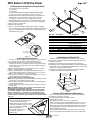
Adjusting for Level or Center of Gravity
Installing Projector
Generally, the video projector should be suspended from the Projector
Pan according to projector manufacturer’s instructions and recommended
standard ceiling mounting hardware.
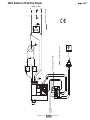
The Scissor Lift SLX has a grounded 220V AC power cord for projector
power supply. The power cord is laced down the back scissor and is “hot” at all
times.
Control cables should be laced through our Cable Management System.
Make sure to use flexible cables, and to allow enough cable at each turn
so cables do not stretch or kink. This will ensure that cords do not become
tangled and damaged during Scissor Lift SLX operation.
Unit and projection system should be operated, checked and adjusted as
necessary at this time.
NOTE: Immediately upon completion of the surrounding ceiling, units should
be operated to confirm that optional ceiling closure panel stops just short of
touching ceiling in closed position.
Warning: Keep fingers and other objects away from automatic ceiling
closure and scissor mechanisms when unit is operating. Serious injury or
damage could result.
①
②
③
④
⑤
⑥
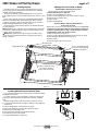
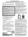
Preferred Method—Adjusting Projector Pan
The Projector Pan can be moved forward or back.
Make sure Bottom Pan is supported.
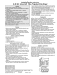
Remove the Lifting Cable Bar (see Fig. 2).
Remove screws holding Projector Pan on Bottom Pan (see Fig. 2).
Move Bottom Pan forward or back.
Replace screws.
Replace Lifting Cable Bar.
Secondary Method—Adjusting Lifting Cable Bar
(if above does not work)
Run the unit to its "Service" position and make sure pan is level. Try and set
so that pan is not more than 19 mm out of level. However, the pan does
not have to be perfectly level, as long as the positioning is consistent
and repeatable in "Show" and "Closed" positions.
① Make sure Bottom Pan is supported.
② Remove screws holding Lifting Cable Bar to the Bottom Pan (see Fig. 2).
③ Move Lifting Cable Bar forward or back (see Fig. 2).
④ Replace screws.
⑤ Check level again. If still not level, repeat.
Attachment points
for Lifting Cables
Lifting Cable Bar
3
/8"-18 x 1" (25.4mm) hex head
cap screws for attaching Lifting
Cable Bar to Bottom Pan
¼"-20 x ¾" (19mm) hex head
cap screws for attaching
Projector Pan to Bottom Pan
Figure 2
Installing Optional Universal Projector Mount
If you ordered the unit with optional Universal Projector Mount pre-installed,
disregard these instructions.
If you did not order the mount pre-installed, you will need to install a new
Projector Pan, which includes the Universal Projector Mount's rectangular
plate.
Maximum weight capacity for the Universal Projector Mount is 11.7 kg.
① Lower unit until the Bottom Pan is resting on a tabletop or other stable and
sturdy surface.
② Remove Lifting Cable Bar from Bottom Pan (see Fig. 2).
③ Remove bolts holding Projector Pan to Bottom Pan (see Fig. 2).
④ Remove Projector Pan and set aside.
⑤ Place new Projector Pan with Universal Mount into place.
⑥ Re-attach Projector Pan to Bottom Pan.
⑦ Re-attach Lifting Cable Bar to Bottom Pan.
7"
21/16"
315/16"
12"
Figure 3
www.draperinc.com
(765) 987-7999